To avoid these ads, REGISTER NOW!

The Wait: a 30X40 Residential Detached Build

OP
C

CamMark

Well-known member
Joined
Oct 1, 2020
Messages
77
Location
Palmetto State
I'm happy to report that we passed final inspection this week for plumbing and electric. The only thing we had to fix to pass was adding a GFCI outlet.

I started sheeting the interior with 7/16" OSB which I painted ahead of time with a coat of Valspar 4000 in flat "Repose" gray. I'm using a 1.5" cabinet screw spaced every 16" or so for install. I have also left 3/4" gap from the lower edge of the sheet to the floor to help avoid wicking up spills or mop water.
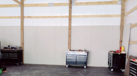
2023-04-19 12_01_49-Window.png

I expect to get all the walls covered up to the 8ft height with 32 sheets in total. Including 5 gallons of paint and the nicer-than-needed hardware I should still come in under $500 for the interior-wall-finishing project.

We have had enough days in the mid 80s now to realize that the ventilation upgrade needs to happen sooner than later. My target has been to clear the building in around 2-3 minutes (recommended for engine exhaust and welding fumes) which will require about 6,000-8,000 CFM.

For most "economy" shutter mounted exhaust fans (i.e. in budget) I would need a 36" unit for that flow rate. As it turns out though that won't fit the truss bracing! So I have decided to go with two 24", 2-speed fans. The cost increase is marginal and this set up will allow for
4 5 different flow rates, in theory.

I marked out the edge of the flange with masking tape for visual confirmation/test fit. Left side aligned with center.
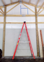
2023-04-19 11_50_09-Window.png
 
Last edited:
To avoid these ads, REGISTER NOW!

outinthetallgrass

Active member
Joined
Dec 28, 2022
Messages
33
I count 5 different air flow rates with a 2, 2 speed fan setup.
1. One fan low
2. one fan high
3. One fan high, one fan low
4. both fans low
5. both fans high
 
OP
C

CamMark

Well-known member
Joined
Oct 1, 2020
Messages
77
Location
Palmetto State
I count 5 different air flow rates with a 2, 2 speed fan setup.
1. One fan low
2. one fan high
3. One fan high, one fan low
4. both fans low
5. both fans high
right, because each fan has three states including "off" not two, but it would be silly to include the zero flow state when both are off. good catch!
 
OP
C

CamMark

Well-known member
Joined
Oct 1, 2020
Messages
77
Location
Palmetto State
The first of the two shutter fans arrived yesterday. I am underwhelmed by the build quality, but not really surprised or discouraged by it. The unit cost was less than what I would expect to pay for the motor alone in the 1/3hp range.

The first thing I noticed when unpacking the fan was that one of the mount "tabs" or loops had broken free from it's welds. So I checked the three that were still attached and found one more which had partially failed but not to the point of total separation. I removed the wire frame or cage from the shutter assembly, then the fan blades from the motor and finally the motor from the cage. I'll remove the paint and get some proper welds in there for all four corners.

2023-04-27 08_40_45-Window.png

The motor was held to the cage with doubled fender washers and ESNA or nylon lock nuts. However the connection of the cage to the shutter baffle, was a bolt, washer and what I believe are threads formed in a friction drilling operation into aluminum sheet. Seeing as I plan to spend a fair amount of time standing 12ft below two of these 20lb face-rearrangers... I will be upgrading that connection and adding lock nuts.

2023-04-27 08_40_21-Window.png

The two speeds are controlled with a pull chain on the motor terminal box. The box also has knockouts which could be used for adding some conduit to feed a switch box at an accessible height on the wall if so inclined. For now I will probably just add some string through a few eye-bolts or something and leave that for a future upgrade.
 
OP
C

CamMark

Well-known member
Joined
Oct 1, 2020
Messages
77
Location
Palmetto State
While I was getting started with the weekend to-do list for the shop we discovered a female turtle had decided to lay her eggs at the edge of the porch. She had dug a few spots on the slope behind the shop as well.

2023-05-01 09_58_03-Window.png

Inside the shop I got the utility sink fully installed. It passed the leak test on the first try. I'll admit though that it took 3 trips to the hardware store to get all the right parts together to plumb it up.

2023-05-01 10_10_17-Window.png

I got some more done on the ventilation project as well.

2023-05-01 09_58_51-Window.png
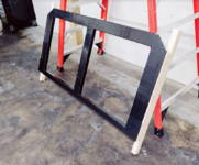
This is the frame that will fit within the gable end truss opposite the drive door. It's covered in butyl tape (exterior face) for extra moisture protection. I have some white aluminum flashing to cover the central divider and the rest will be framed with some leftover J-trim.

My plan is to install this frame from the inside and use it as a template to cut the insulation. Then put a drill through at the corners and move outside to cut the siding corner-to-corner. I can then slip the flashing and J-trim in place, mount the fans and caulk as needed.

It all sounds good in my head, but this will be the first time doing any significant work on a steel siding building so I welcome input from anyone with more experience.
 
OP
C

CamMark

Well-known member
Joined
Oct 1, 2020
Messages
77
Location
Palmetto State
My 7yo quality inspector discovered an issue with my faucet install at the utility sink. Since I only had cold water and only needed cold water I had only hooked up the cold water line and left the "hot" line loose. Well when she tested the valve in the hot position of course pressure from the cold side flowed through the blend area of the valve and out of the "hot" hose onto the floor. Not a show stopper, but undesirable.

An $8 and 5 minute fix to add a 3/8 run tee at the supply valve resolved the issue.

While I had my plumber hat on why not add a hose spigot to water plants and wash cars? I popped a hole through the siding lining up with the lowest girt (to use as secure structure) then tee'd into the supply near the toilet rough-in. I applied a liberal amount of clear silicone to the back of the sillcock and installed with some gasketed metal roofing screws I had handy for the next project on the list.

Exhaust fan install. After getting the frame secured in place with screws and mending plates (maybe overkill?) I cut out the insulation with a utility knife. My plan was to punch a small hole in each corner of the metal siding from inside, then go outside and connect the dots with [insert powertool here], but unsurprisingly this clearly well thought through plan /s did not go so smoothly.

I ended up choosing a large, unwieldy corded "sawzall" (6 year old Kobalt) because I had the right blade for that tool to make the cut from inside, following the frame edges. This only worked at just the right speed- too fast and I couldn't keep it straight and away from gouging the frame. Too slow and rather than making a cut it just snagged the siding and vibrated the whole end of the building. Hitting that sweetspot in the middle proved more challenging that expected.

I pivoted to some offset sheet metal snips. This was time consuming but controllable. It would have been even better if I had left hand and right hand cuts. I managed, but I'll be picking up a set of left hand snips before I tackle the next cutout.

I trimmed out the opening with some J-trim the builders left behind and bent up a drip edge/sill from some white aluminum flashing. There was nothing pre-formed and available locally that had the right dimensions, especially the depth. This should work well enough even if it has a bit of a "home made" look to it.

2023-05-08 07_58_23-Window.png

After my tack welds to repair the wire mounting frame that arrived partially assembled I gave a coat or two of light grey rustoleum to clean it back up and help it blend in a bit (was black initially).

2023-05-08 07_58_55-Window.png

I connected temporary power and pull string for testing. On it's own it does a fairly decent job keeping the building comfortable on an 82° day. Still need to get #2 in place and feed some romex to the outlet box on the adjacent post.

All in all it was a productive but exhausting weekend. Pun intended.
 
OP
C

CamMark

Well-known member
Joined
Oct 1, 2020
Messages
77
Location
Palmetto State
Thanks!

Yep, that's what I was going for but somehow grabbed the wrong one while wrangling two 3YOs. I have the right hand, just need to buy a left hand to go with it.
 
Last edited:
OP
C

CamMark

Well-known member
Joined
Oct 1, 2020
Messages
77
Location
Palmetto State
I have been pretty busy since my last post, both with the shop project and the rest of life.

So here is a quick rundown of progress:

-Both exhaust fans are now installed permanently (not fed by extension cords...).
-Added a hose outside, mostly for watering the potted plants and feeding the pressure washer.
-Wired up and installed secondary interior lights.
-Nearly finished the interior wall panels excluding the area where the bathroom will go.
-Moving in all the stuff one truck-bed full at a time

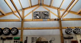
2023-06-30 08_55_39-Photo.png
"dual exhaust"

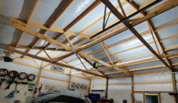
2023-06-30 08_57_13-Photo.png
secondary up-lighting

2023-06-30 08_53_45-Photo.png
primary overhead lighting for reference

2023-06-30 09_04_56-Photo.png
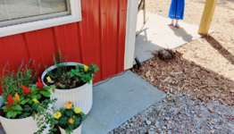
I didn't have a clear photo of the hanger mounted, but added this inset to show it.

The next milestone will most likely be the bathroom. I have a reasonably accurate budget worked out as well as a rough sketch of the framing and layout. I may even get fancy and go with painted finish plywood on the inside instead of OSB. Sometimes you gotta treat yourself... And to keep the footprint as minimal as possible, I am planning to use a pocket door.
 

mmelton005

Well-known member
Joined
Dec 16, 2014
Messages
245
Location
West KY
Silly question, What size is your overhead door & the width of the porch? I am planning a project almost identical to this.
 
OP
C

CamMark

Well-known member
Joined
Oct 1, 2020
Messages
77
Location
Palmetto State
Silly question, What size is your overhead door & the width of the porch? I am planning a project almost identical to this.
It's a pretty good question I think. We put a lot of thought into getting the dimensions just right.

The door is 16' wide by 10' tall.

The lean-to porch runs the length of the 40' building and the concrete pad is 8' wide (deep?) The posts are set back a foot from the edge. I may have been better off with 10' in hindsight, but the 8' serves the purpose well.
 

mmelton005

Well-known member
Joined
Dec 16, 2014
Messages
245
Location
West KY
It's a pretty good question I think. We put a lot of thought into getting the dimensions just right.

The door is 16' wide by 10' tall.

The lean-to porch runs the length of the 40' building and the concrete pad is 8' wide (deep?) The posts are set back a foot from the edge. I may have been better off with 10' in hindsight, but the 8' serves the purpose well.
Thank you! I am trying to cover all my bases before I give the go-ahead to the builder. That is the last thing I want is wish I would have done something different. Thanks for the update
 
To avoid these ads, REGISTER NOW!
OP
C

CamMark

Well-known member
Joined
Oct 1, 2020
Messages
77
Location
Palmetto State
Getting some use now out of the new building working on projects, doing some vehicle maintenance and a little troubleshooting here and there. I'm beginning to get a good feel for what layout works best and where to put some of the more permanent fixtures.

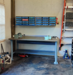
This table served as the primary work surface back in the attached garage. The small parts bins in the cubies above work really well, but I'll need to double it to fit everything still in the unsorted bins. And this area needs some task lighting and an outlet or two. I plan to run another 20amp circuit along this wall for the outlets.

2023-11-07 08_16_30-Window.png

I'll pull off a new 15 amp circuit for the light which will be shared with the bathroom I recently framed up.

The door opening looks way too big... but that's to fit the pocket door framework.
2023-11-07 07_45_42-Window.png
The ceiling structure is intended to be load bearing so I can use that space for storage without concern.

The exterior will get the same painted OSB to match the rest of the space. Still undecided on the interior, but probably bead board with a water resistant coating- maybe poly over a white-wash stain, maybe a few heavy coats of a white semi-gloss. Cheap and effective is the goal.
 

cccoltsicehockey

Well-known member
Joined
Apr 3, 2014
Messages
1,418
Location
Charlotte, NC
Lights!

2023-02-13 08_14_53-Photo.png

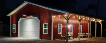
This has been the most difficult part to visualize mentally so it's a big relief to see that it looks even better than imagined. The string lights on the lean-to are run along a 3/16" tensioned steel cable to keep them straight. the run was exactly 48' so it would have come up short had we let it hang down a bit.

JbTech, the gooseneck is a 23" Redondo from Steel Lighting co. Link. My wife was particular about the exterior stuff so I left that up to her. I probably would have found something cheaper, but I think it was worth the cost. I'm impressed with the quality of materials and finishes and expect it to hold up well.
Great looking build. The exterior lighting is really nice.

Do you have any pictures of the Redondo in the daylight on your building? The light output looks fantastic in that picture. I am thinking of mounting a single one of those exact lights from Steel Lighting Co. to match the existing house lighting position over each of my 18x8 doors. How wide would you say the light output is and at what height is yours mounted? Sorry for all the questions but I appreciate any info you can share on it.
 
Last edited:
OP
C

CamMark

Well-known member
Joined
Oct 1, 2020
Messages
77
Location
Palmetto State
Great looking build. The exterior lighting is really nice.

Do you have any pictures of the Redondo in the daylight on your building? The light output looks fantastic in that picture. I am thinking of mounting a single one of those exact lights from Steel Lighting Co. to match the existing house lighting position over each of my 18x8 doors. How wide would you say the light output is and at what height is yours mounted? Sorry for all the questions but I appreciate any info you can share on it.
Thanks!

Back on post #12 there is a photo of the fixture in the daylight.

I don't recall off hand the spec on the bulb, BR or PAR. The reflector within the bulb is doing most of the work. The shade is only getting a fraction of the output to redirect.

But you've got me thinking now... what would it look like with a common A-series bulb? I may play around with that...

I recall there being a recommended install height in the instructions. Somewhere in the ballpark of 12" from the bottom of the shade to the edge of the door opening. 10' tall door, so 11' from the light to the ground.
 

cccoltsicehockey

Well-known member
Joined
Apr 3, 2014
Messages
1,418
Location
Charlotte, NC
Dang, I scrolled through twice and somehow still missed that picture. Thanks.

Thanks, I will have to look into those dimensions then. My current light is about 2ft above my existing door on the house so that sounds like it might be perfect then.

Be interested to hear what you find if you end up trying other bulbs.
 
OP
C

CamMark

Well-known member
Joined
Oct 1, 2020
Messages
77
Location
Palmetto State
The waiting is officially over. The vision fully realized. And, crucially funding from the "big pot" has ceased. :giggle:

Installation of the 2-post lift was the final item on the project list that we were waiting on. That is now in place and in regular use! The installers did their part in just over 2 hours and I had the electrical work wrapped up that same day.

I was for a long time planning on a Bend Pak GP-7 for the "narrow bay" design aspect. While I have the width available for a traditional 2-post, I still wanted to make the best of the space I have by minimizing the foot print of everything I put in it. But, it occurred to me while watching a YouTuber who uses that same model that the narrow column design forces the hydraulic power unit onto the side rather than front/back. That actual overall width isn't in the documentation so this seems more compact than other lifts meant for tight spaces.

I reevaluated my short list of other lifts I had considered with this fact in mind and found the Challenger VLE10 to be a much better fit. On paper it's about 6" wider, but offers 4" more space to walk by on the side where the power unit is. There were some other benefits to the VLE10 over the GP-7 including the 3k lb capacity advantage and shorter overall height, coming in 1/8" short of 12' which worked, much better in my situation. It also didn't hurt that it was available in a color that matches the exterior of the building. It's the small things sometimes.

Screenshot 2024-09-03 104728.png

It's not real clear from this angle, but there is no more than 1" clearance to the brace board overhead. The GP-7 would have required more clearance.

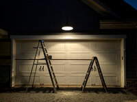
In response to post #56, below is a look at the Redondo with a common 40watt equivalent LED bulb. It does have a wider cast and I think I'll keep it this way.

2024-09-03 085924.png

You may also notice more plants were added since the last update. Fans on the lean-to were also a recent addition. 42" "Cassius" with a 36" down rod for anyone wondering.

I'll probably have more to share on the interior once it's all reorganized to better suit the new addition.
 

cccoltsicehockey

Well-known member
Joined
Apr 3, 2014
Messages
1,418
Location
Charlotte, NC
The waiting is officially over. The vision fully realized. And, crucially funding from the "big pot" has ceased. :giggle:

Installation of the 2-post lift was the final item on the project list that we were waiting on. That is now in place and in regular use! The installers did their part in just over 2 hours and I had the electrical work wrapped up that same day.

I was for a long time planning on a Bend Pak GP-7 for the "narrow bay" design aspect. While I have the width available for a traditional 2-post, I still wanted to make the best of the space I have by minimizing the foot print of everything I put in it. But, it occurred to me while watching a YouTuber who uses that same model that the narrow column design forces the hydraulic power unit onto the side rather than front/back. That actual overall width isn't in the documentation so this seems more compact than other lifts meant for tight spaces.

I reevaluated my short list of other lifts I had considered with this fact in mind and found the Challenger VLE10 to be a much better fit. On paper it's about 6" wider, but offers 4" more space to walk by on the side where the power unit is. There were some other benefits to the VLE10 over the GP-7 including the 3k lb capacity advantage and shorter overall height, coming in 1/8" short of 12' which worked, much better in my situation. It also didn't hurt that it was available in a color that matches the exterior of the building. It's the small things sometimes.

Screenshot 2024-09-03 104728.png

It's not real clear from this angle, but there is no more than 1" clearance to the brace board overhead. The GP-7 would have required more clearance.

In response to post #56, below is a look at the Redondo with a common 40watt equivalent LED bulb. It does have a wider cast and I think I'll keep it this way.

2024-09-03 085924.png

You may also notice more plants were added since the last update. Fans on the lean-to were also a recent addition. 42" "Cassius" with a 36" down rod for anyone wondering.

I'll probably have more to share on the interior once it's all reorganized to better suit the new addition.
Looking good and great update. Has to be great to finally knock the lift off the list.

From your posts and another members, I ended up going with the Redondo lights and am very happy with their quality. For the time being I have a 60w LED equivalent in it right now at 2700k. Right now it is perfect brightness but I might install a dimmer once all three are lighting up the driveway when the build is done.

IMG_20240624_082827.jpg
 
OP
C

CamMark

Well-known member
Joined
Oct 1, 2020
Messages
77
Location
Palmetto State
1999-2000 Civic Si (and 2001-2003 Civic EX) wheels on the left, and 2008-2012 Accord V6 wheels on the right. I smell Honda vehicles!
look a little closer, you'll see a bumper cover (2000 Civic) hanging from the ceiling at the far left, and below the EM1 wheels valve covers from a D16Z6, D16Y8 and F22Ax- but the Isuzu Oasis version which only had "16 VALVE" embossed on it #rarebutnotdesireable
 
OP
C

CamMark

Well-known member
Joined
Oct 1, 2020
Messages
77
Location
Palmetto State
The building got it's first snow! That doesn't happen too often in our area. It's been maybe four years since last time it stuck.

The insulation does fairly well. I was able to maintain mid 50s with two space heaters while outside was in the 20s for several days.
2025-02-04 07_55_16-SHop1.jpg

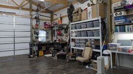
I've been busy with the project car(s) and vehicle maintenance on the daily drivers and helping friends and family with work too. I'm starting to get a good feel for the best place for most things. I'm trying out different storage solutions here and there. I tend to prefer clear bins so I can see what's what. some are even sub-divided with gallon freezer bags to keep small stuff together but categorically in the same bin.
2025-02-04 07_58_00-Shop2.jpg
This corner is probably has the most left to do to get the floor clear and everything put away.

This set up works well for now, but the desk area may get upgraded to shelving with one shelf at desk height. notice the two speakers on the book shelf. I see a lot of posts about shop speakers: This looks pretty unassuming, but performs really well. It's two MTM "overnight sensations" by Paul Carmody which I have linked to the plans if you're into that kind of thing- being powered by a small Pyle 100w BT chip amp. The drivers are pretty tough so time will tell if they hold up to the environment.
2025-02-04 07_59_24-Shop3.jpg

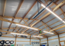
The lift is rarely empty and the main work area at the front is taking shape. Task lighting is a set of twin tube T8s I had on hand with some 5k LED tubes installed. This is a trial install to see what works and what doesn't. Something with more direct light like this that can be mounted further away may be better.
2025-02-04 08_00_16-Shop4.jpg
The lift is getting used regularly and I am now spoiled. Space on ingress/egress is a bit tight with full size trucks so getting it well centered is key. Being able to pull a car in and be under it comfortably in 5 minutes is my definition of true luxury.

I have also recently fabri-cobbled internet access/wifi with a wireless bridge from the house. It was surprisingly easy to set up, but being sure I had the right thing without over spending was a challenge. For the bridge kit and access point for inside the total was about $120. I had two 6ft cat6 cables handy, but that was the only other thing I needed to get it working.
 
To avoid these ads, REGISTER NOW!
Top Bottom