To avoid these ads, REGISTER NOW!

RBW makes a float-loc vise.

RaisedByWolves

Well-known member
Joined
Feb 4, 2023
Messages
3,629
Location
SE PA.
EDIT: You can download the prints for this vise here.


You’re probably thinking…He did a what?

It’s a type of low profile drill press vise to keep you from losing a finger when drilling small or flat items.

A link to plans will be added right here when I get to a real computer.

I get some free time at work every now and then so to stay busy I like to make tools that will make my life easier.

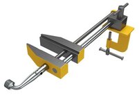
Sometimes we need to drill flat or irregular pieces that either won’t fit in a regular vise or are such that you need to raise and lower the head. This can be time consuming and this leads to people taking short cuts, the most common of which being holding the item by hand.

Looks like this:

?u=https%3A%2F%2Ftse2.mm.bing.net%2Fth%3Fid%3DOIP.jpg
These were sold as cast iron castings and also mild steel and tool steel by various manufacturers over the years, and were quite expensive for what they are and bring a premium on the used market.


I’ll be making this out of A2 tool steel and hardening, then drawing back to 45-50 Rockwell, but that is mostly because I can.

So here we go!

I skipped ahead a bit as showing pics of bandsaw cut bar stock just seemed unnessary.

Here you can see the jaws of the vise cut and milled to size and profiled. The steps in the jaws offer another height for clamping your part similar to using parallels in a milling vise.

IMG_2368.jpeg


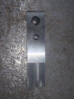
Next up was drilling and reaming the holes for the alignment bar and the screw. This is done with the parts ganged up in the mill to ensure the holes line up.

IMG_2370.jpegIMG_2369.jpeg


Next up, tapping the 1/2”-10 ACME thread and making the rods.
 
Last edited:
To avoid these ads, REGISTER NOW!

JradM

Well-known member
Joined
Sep 4, 2019
Messages
1,821
Location
Alberta
I take it you clamp the vise to the table, then can slide/rotate the jaw part into whatever position is needed and clamp it securely?

I've never seen this style of vise before. Looks good so far!
 
OP
R

RaisedByWolves

Well-known member
Joined
Feb 4, 2023
Messages
3,629
Location
SE PA.
I take it you clamp the vise to the table, then can slide/rotate the jaw part into whatever position is needed and clamp it securely?

I've never seen this style of vise before. Looks good so far!
You got it.


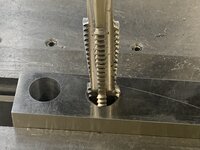
Next step, tapping the hole.

As mentioned, this is an acme thread which will transmit linear force better than a standard thread due to the thread profile and angle.

This tap is a duplex style and not my favorite.

These taps are a ***** to use and flex considerably in use. They flex enough that you’re near the point of breaking the tap right as it cuts. Usually you need to turn a tap 1/4th of a turn and then turn it backwards to break the chip. With this tap I was only able to turn it maybe 1/20th of a turn for the first half, then a little more for the second.


IMG_2372.jpeg

A tap follower/pusher is required to keep everything in line to assure correct cutting action.

If I had some better cutting fluid this might have gone easier, but the problem with this tap design is the first part of the duplex is cutting on both sides as well as the end of each tooth, and the resulting chip crowds in on it’s self.

The second part of the tap cuts slightly easier as it’s only cutting a chip on either side to form the required thread profile.

Did I mention these suckers are long? I had to hang the jaw off of the side of the vise to get the tap through.


IMG_2373.jpeg


The next step will be boring.
 

subroc

Well-known member
Joined
Apr 22, 2017
Messages
781
Location
Dover, NH
I have one. It is sitting on my 13" drill press. I am 68 years and had never seen one untill i got this a couple years ago. Mine came with a 15" drill press. I paid $50 for the whole thing, press and vise. Knowing what I know now the vise is worth more to me than that press.

i followed mr pete on his vise build on YouTube. Looked like a solid project. I'll follow this as well. You are doing a good job.
 

RoninB4

Well-known member
Joined
Jul 22, 2020
Messages
3,618
Location
Under My House
-Made from A-2? 4140 PH wasn't available or good enough? Will you be heat treating it? Nice project, great for plate work.
 
OP
R

RaisedByWolves

Well-known member
Joined
Feb 4, 2023
Messages
3,629
Location
SE PA.
-Made from A-2? 4140 PH wasn't available or good enough? Will you be heat treating it? Nice project, great for plate work.
We do mostly die repair so we have tons of A2, D2 and O1, but little else as far as tool steel. I do a lot of fixturing and gauging so I have tons of Aluminum and brass, but this was my best option and we can harden this in house.

OK, lets get boring.

The driven jaw on this vise needs to slide along the guide rod where as the other jaw is a running press fit and pinned. I used a 1/2" on size reamer on both holes so the one on the movable jaw needs to be opened up .003. That is .002 for the sliding action and .001 for the hole to shrink when it is hardened. There's a whole bunch of metallurgical stuff that goes on when steel is heat treated, but I wont get into that, suffice it to say the hole will shrink a bit.


First things first, I need to find the center of the hole. This is one of my favorite indicators to use. Expensive, but it is simple to use and saves time over a co-ax. I probably saved 30-40 seconds going with this over the co-ax.:geek:


IMG_2375.JPG


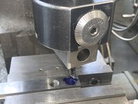
Once I found the center I set up the boring head and a boring bar and found my hole edge, then dialed in .003 for my cut. The Boring head has a micrometer dial that makes this relatively simple and painless. I blued the hole to indicate when I first touched and after using my fancy indicator found I was off, WTF? You can kind of see a little half moon forming on the right side of the hole.

Broke out the Haimer again and everything was spot on.:unsure:

Turned out the hole wasn't clean and my Dykem was thick in that spot and just flaked off.


IMG_2376.JPG


Here's the finished hole. Its actually smoother than it looks. The phone was zoomed in and all the shiny surfaces combined with the flash made the pic very grainy. This may get honed later after hardening depending on how much it shrinks and or how well it travels up and down the rod.


IMG_2383.JPG


Next I turn the Acme rod to fit the fixed jaw and the Oo Bracket that holds the other end of both rods.

Im calling it an Oo bracket as I have no real name for it and that is what it looks like, a big hole and a small hole in a cone shaped piece of steel.
 
To avoid these ads, REGISTER NOW!
OP
R

RaisedByWolves

Well-known member
Joined
Feb 4, 2023
Messages
3,629
Location
SE PA.
I have one. It is sitting on my 13" drill press. I am 68 years and had never seen one untill i got this a couple years ago. Mine came with a 15" drill press. I paid $50 for the whole thing, press and vise. Knowing what I know now the vise is worth more to me than that press.

i followed mr pete on his vise build on YouTube. Looked like a solid project. I'll follow this as well. You are doing a good job.
You hit the lottery there! Thanks for the kind words.

Nice project. Mr. Pete aka Tubalcain on YouTube made a similar tool not too long ago. Seems very handy.


I honestly cant watch him. Not that he's bad or necessarily gives bad advise, I just don't like the way he goes about things sometimes.

I found this via Blondiehacks. Shes much more relaxing for me to watch as I'm not looking for info, I just want to vedge out and watch someone make something.
 
OP
R

RaisedByWolves

Well-known member
Joined
Feb 4, 2023
Messages
3,629
Location
SE PA.
ADD has been kicking my *** lately so I haven’t worked on this much, but today I finished another couple steps.

I got the acme rod brought to length and turned to size on the ends, and got the slide rod finished.


Oh, I cut the V for round stock cut in the fixed jaw.

Starting to look like something.


IMG_2468.jpeg
 
Last edited:
OP
R

RaisedByWolves

Well-known member
Joined
Feb 4, 2023
Messages
3,629
Location
SE PA.
What type of cutter did you use for the V in the jaw, and was it on a vertical or horizontal mill?
Standard Bridgeport mill and I uses a 90* point carbide endmill.

I get a lot of non standard work and whenever I can get the engineer asking for this type of work yo buy me some type of cutter I don't have, I do so. I have a job right now that would take me two days if I had a 150* cutter, but no such thing exists AFAIK. As it stands Ill make due, but its going to be 16 different setups with collet blocks and each setup will introduce errors so were looking at a week minimum.

If we had a dividing head it would be maybe 3 days, but we don't so I have to do it caveman style.


The last vise I made I did tilt the head 45* to make that cut and the hardest part of that was finding center with the head tilted.
 

RoninB4

Well-known member
Joined
Jul 22, 2020
Messages
3,618
Location
Under My House
I have a job right now that would take me two days if I had a 150* cutter, but no such thing exists AFAIK. As it stands Ill make due, but its going to be 16 different setups with collet blocks and each setup will introduce errors so were looking at a week minimum.
-Must admit I'm a little intrigued by your description and the challenge. Care to show a drawing? Needn't be anything violating intellectual property rights, a napkin sketch will do.
 
OP
R

RaisedByWolves

Well-known member
Joined
Feb 4, 2023
Messages
3,629
Location
SE PA.
-Must admit I'm a little intrigued by your description and the challenge. Care to show a drawing? Needn't be anything violating intellectual property rights, a napkin sketch will do.

Honestly, I don't use drawings unless someone hands me one, everything is right out of my head. I figure if I make drawings someone else can do my job, so all of my notes are just equations with no reference. I know what they are, but good luck if you try to figure it all out.


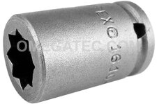
But basically I have to make this:

n.com%2Fimages%2FI%2F418Y%2BxQzFwL._AC_UL640_QL65_.jpg


Fit into this:


apex-1-4-square-drive-socket-sae-double-square-nut.jpg


At a custom size for an automated assembly machine.

Its one of those "We will build it so it cant be copied and they will need to buy everything from us" type situations.

The parts as supplied don't really wear out, but we need to check torque and the torque tester we have and the assembly machine manufacturer use different drives so I need to make a coupling to mate the two.

Either that or buy their torque tester for ~ $20K.
 

may0naise

Well-known member
Joined
Dec 2, 2018
Messages
217
Location
Arizona
This is looking good. If you want to see it, blondihacks did a whole build series on making one of these on youtube. here is the final completion.
 

RoninB4

Well-known member
Joined
Jul 22, 2020
Messages
3,618
Location
Under My House
Its one of those "We will build it so it cant be copied and they will need to buy everything from us" type situations.

I need to make a coupling to mate the two.

Either that or buy their torque tester for ~ $20K.
-Proprietary components....been there too and can't say that I disagree with a company protecting future sales. This does make it a large PITA for the toolroom or becomes job security, depending upon how you view it.

-Seems like some sort of tooling budget should be figured in for such a project, especially if it will have to be repeated. Saving 20k ought to pay for itself AND something to facilitate the job like an indexing fixture or a decent rotary table. An index plate could even be made to use in conjunction with whatever you already have, you've likely already considered this.

-Looks like two squares (8 points) superimposed over each other at 45 degrees with a hex drive on the other end?

-I wasn't asked to stick my nose into your project, apologies if I've crossed the line, The challenge of how to make things still piques my interest. Does Pavlov ring a bell? No, but I still salivate.
 
To avoid these ads, REGISTER NOW!
Top Bottom