To avoid these ads, REGISTER NOW!

The VISES of Garage Journal

genog

Well-known member
Joined
Sep 4, 2021
Messages
2,015
Location
Silicon Valley
You did a great job cleaning the vise up. It looks like it’s in lightly used condition and the natural finish really suits it. The vise is from the early 20’s so it’s right around 100 years old.
Thank you Smitty
Much obliged 👍

I am proud of the ole boy
He's in the shop, back to work
 
To avoid these ads, REGISTER NOW!

genog

Well-known member
Joined
Sep 4, 2021
Messages
2,015
Location
Silicon Valley
Just Citrus stripper to remove the layers of old paint
Wire brush with a die grinder
Used a couple different profiles...

Then Watco Danish Oil (which is probably just Linseed Oil with a dryer)
 

Shiftless

Well-known member
Joined
Mar 9, 2014
Messages
14,577
Location
East Bay SFO
Just Citrus stripper to remove the layers of old paint
Wire brush with a die grinder
Used a couple different profiles...

Then Watco Danish Oil (which is probably just Linseed Oil with a dryer)
Watco…interesting!
I refinish teak furniture from time to time and use uncolored watco and walnut tinted watco.
Did you use the uncolored “natural” or something else?

thanks!
 

genog

Well-known member
Joined
Sep 4, 2021
Messages
2,015
Location
Silicon Valley
Watco has a dryer of some sorts. It dries while regular BLO takes forever to
The formula for Watco may have a Japan Drier..... an ole woodworker/finish man would know

Since I have a can of Teak oil that I need to use up... I covered the ole Prentiss in Watco Teak Oil Finish
....I don't think it matters
Natural is a good choice
 

RBarnes

Well-known member
Joined
Mar 2, 2018
Messages
421
Location
Texas
"Nice work RBarnes. Only suggestion is radius those sharp corners so you don’t cut your fingers pulling the pins out. Are they 3 degrees per side? Just curious to what angle you came up with."


They are smoother on the edges than the angle of the photo indicates. The 404 bottom row shows the radius better. Basically tried to copy originals - minus the beating/wear marks. They could be radiused more pretty easily. Figured I would post photo in case someone needs a pin for their Reed 406 405, or 404 vise.

As far as the angle, I don't know. Still haven't figured out how to convert "taper per foot" to angle degrees. Just used the taper attachment on my Logan 1957, copied taper of original. I do know that my proto types would not work correctly if I slightly varied the taper attachment setting one way or the other. Original 406 & 405 pins are in the left side of photo with ones I turned on the right side.
 
Last edited:

dieselsmoke

Member
Joined
Jul 25, 2013
Messages
23
Location
North of Pittsburgh PA
Hi guys, been a long time since I posted but I only post when I find a cool vise, and I have been skunked for several years finding a noteworthy one. Then this morning...I actually completed a FB Marketplace transaction :LOL:

Lick your chops...7" Williamson :love: I've only ever seen a few examples of these, and never a 7". ANYTHING 7"+ is rare, period.

Astute readers will note that the tongue is broken out of it, but I'm a machinist and fab guy, so this will get repaired to look great and function great too. I never get upset about broken stuff...it's all part of the story when you bring it back to life.

Hope yinz like it!
 

Attachments

  • W7 side.PNG
    W7 side.PNG
    2.3 MB · Views: 106
  • W7 top.PNG
    W7 top.PNG
    3.1 MB · Views: 82
  • W7 jaw.PNG
    W7 jaw.PNG
    2 MB · Views: 72

Smitty

Well-known member
Joined
Sep 4, 2018
Messages
2,409
Location
USA
Watco has a dryer of some sorts. It dries while regular BLO takes forever to
The formula for Watco may have a Japan Drier..... an ole woodworker/finish man would know

Since I have a can of Teak oil that I need to use up... I covered the ole Prentiss in Watco Teak Oil Finish
....I don't think it matters
Natural is a good choice
That’s a great idea using Watch oil. I just looked it up and you are correct, it’s boiled linseed oil based. My question to you is how well does It dry. After giving it a few days to cure will the color come off on a rag if you wipe it down? I use BLO a lot and once fully dry it’s like varnish.
 

Attachments

  • 1AC7B55F-9F2F-4494-9387-643D86A337F2.png
    1AC7B55F-9F2F-4494-9387-643D86A337F2.png
    526.5 KB · Views: 67

Shiftless

Well-known member
Joined
Mar 9, 2014
Messages
14,577
Location
East Bay SFO
That’s a great idea using Watch oil. I just looked it up and you are correct, it’s boiled linseed oil based. My question to you is how well does It dry. After giving it a few days to cure will the color come off on a rag if you wipe it down? I use BLO a lot and once fully dry it’s like varnish.
:+1: To that

Like, Smitty does, I use BLO a lot and find that it ultimately hardens up to resemble varnish.
I am going to try some Watco on a vise. I use Watco on my 50’s vintage teak furniture. If you follow the directions, it dries (hardens) OK
I apply with a rag and rub it in to the wood. After 5-10 minutes I rub along the grain with a terrycloth towel to remove anything that didn’t soak in. The next day it is pretty hard but it takes several more days until it is what most people would call hard. I don’t put anything onto the table for several days.
Im sure that since cast iron is a lot less porous than oiled teak wood, results will be much different. I think baking would be in order for a Watco Danish Oil cast iron vise project. I intend to try dark walnut colored Watco as well as Natural.
 

dannyr

Well-known member
Joined
Oct 13, 2019
Messages
283
Location
Sheffield England
Patrickm82: I have a very nice Reed 214R [filer's vise]. It too has almost mint jaw serrations.
The dynamic is close to becoming a two-piece item like your 204R..

What is amazing is just how much metal is in this location and yet the vice failed.
Looking at my vise, the crack is complete all the way around the bottom of the dynamic but not at top of the slide where
it becomes the jaw tower. This implies that the forces that caused the crack were directly opposite clamping forces.
I cannot imaging what could have been done to this vise to cause the crack, and not leave a very noticable mark on some other part of the vise.
The only vague possibility is that the vise was dropped onto the top face of the dynamic jaw square onto a solid floor, causing enough force to attempt to separate the jaw tower from the slide..

PierceA

REED 214.jpgREED 214A.jpgREED 214B.jpgREED 214C.jpg

I always admire the hefty 'cheeks' on the dynamic of big US vises - but maybe that's actually a casting problem - not a foundryman myself but used to deal with them - one of the things I think I picked up was that changes in section thickness could be points of weakness - as I understand it the thinner section solidifies first then there can be porosity developing along the line where it becomes thicker and solidifies later -- line of weakness. Can counteract somewhat with good choice of feeder/riser position.

Wabbit, on a UK thread (thanks) - showed an early Chas Parker advert I never saw before with wrought iron rod reinforcements --1894 No 3 Parker Parallel Machinist 000 - 6.jpg

I assume these are cast-in, rather than a hole drilled and inserted - might be poss as I think wrought iron has a higher melting point than cast iron, but would absorb at least some carbon on its skin and also both have different coefficient of expansion - raises all sorts of questions but I guess C P tested this. Wonder how long they used it in manufacture - they're obviously seeing this as a point of weakness in other vices.

any foundry metallurgists to check my comments above?
 

genog

Well-known member
Joined
Sep 4, 2021
Messages
2,015
Location
Silicon Valley
Watco dries Faster than BLO because as Smitty pointed out, it is BLO
.....but it contains a drier, some sort of drying agent.
Probably Japan Drier

I wipe the Watco on the old vises and they are dry tomorrow
After an overnight drying session, the finish does not wipe off nor is the finish unstable in any way
The oil puts a nice seal on the metal, kind of like it does to wood.

Over the course of time, layers of Watco puts a beautiful finish on wood. I use it on our furniture, certain gunstocks, speaker cabinets, etc often with a light 0000 steel wool in between coats
Gorgeous
It also looks great on those old vises that I have in the shop
jd.jpg
Maybe try a bit of Japan Drier with your BLO to make it dry faster
 

dieselsmoke

Member
Joined
Jul 25, 2013
Messages
23
Location
North of Pittsburgh PA
I always admire the hefty 'cheeks' on the dynamic of big US vises - but maybe that's actually a casting problem - not a foundryman myself but used to deal with them - one of the things I think I picked up was that changes in section thickness could be points of weakness - as I understand it the thinner section solidifies first then there can be porosity developing along the line where it becomes thicker and solidifies later -- line of weakness. Can counteract somewhat with good choice of feeder/riser position.

Wabbit, on a UK thread (thanks) - showed an early Chas Parker advert I never saw before with wrought iron rod reinforcements --1894 No 3 Parker Parallel Machinist 000 - 6.jpg

I assume these are cast-in, rather than a hole drilled and inserted - might be poss as I think wrought iron has a higher melting point than cast iron, but would absorb at least some carbon on its skin and also both have different coefficient of expansion - raises all sorts of questions but I guess C P tested this. Wonder how long they used it in manufacture - they're obviously seeing this as a point of weakness in other vices.

any foundry metallurgists to check my comments above?
Metallurgist here. You are correct that the wrought iron / steel has a higher melting point, and if thick enough, they will stay in there and provide strength in tension, which is exactly what cast iron ***** at.

If the steel is very fine, like a wire, and you are pouring a lot of metal past that point based on your gating strategy, carbon can diffuse into the wire in real time and it will disappear, becoming totally dissolved into the cast iron. Sometimes when they needed a sand core held in space with no support, they used thin "chaplets" to hold cores for a short period of time before the chaplets melted in.

The trick would be to find (most likely just by experimentation back in that day) the thickness of the steel that survives and stays intact. It will have a carbon diffusion zone around it if it's small enough.

Now just to go to the other extreme, say you put a big 5/8" piece of steel bar in it...it's probably got enough heat capacity that it stays cool enough to not integrate well into the casting....well then you've gone too far and it's a weakness inducer instead of a strengthener. It would all lie in the balance of the section thickness of the casting, and the properties and section of the strengthener to make it work as intended. Too little, or too much, and it fails. Just like in modern day composites.
 

Smitty

Well-known member
Joined
Sep 4, 2018
Messages
2,409
Location
USA
Genog, thanks for the info, I appreciate it. Every once in a while I’ll strip the paint off of an old vise and it has that raw steel look. This would be great to give it more of an old time patina look. I’m going to try this color and see what happens.
 

Attachments

  • F0C352D4-3038-4120-9EEB-88C6181E41BD.jpeg
    F0C352D4-3038-4120-9EEB-88C6181E41BD.jpeg
    78.8 KB · Views: 55

dannyr

Well-known member
Joined
Oct 13, 2019
Messages
283
Location
Sheffield England
Metallurgist here. You are correct that the wrought iron / steel has a higher melting point, and if thick enough, they will stay in there and provide strength in tension, which is exactly what cast iron ***** at.

If the steel is very fine, like a wire, and you are pouring a lot of metal past that point based on your gating strategy, carbon can diffuse into the wire in real time and it will disappear, becoming totally dissolved into the cast iron. Sometimes when they needed a sand core held in space with no support, they used thin "chaplets" to hold cores for a short period of time before the chaplets melted in.

The trick would be to find (most likely just by experimentation back in that day) the thickness of the steel that survives and stays intact. It will have a carbon diffusion zone around it if it's small enough.

Now just to go to the other extreme, say you put a big 5/8" piece of steel bar in it...it's probably got enough heat capacity that it stays cool enough to not integrate well into the casting....well then you've gone too far and it's a weakness inducer instead of a strengthener. It would all lie in the balance of the section thickness of the casting, and the properties and section of the strengthener to make it work as intended. Too little, or too much, and it fails. Just like in modern day composites.

great info -- thanks -- and I guess strength in tension is exactly what is needed at that point
 

genog

Well-known member
Joined
Sep 4, 2021
Messages
2,015
Location
Silicon Valley
Genog, thanks for the info, I appreciate it. Every once in a while I’ll strip the paint off of an old vise and it has that raw steel look. This would be great to give it more of an old time patina look. I’m going to try this color and see what happens.
Hey Carbon Gray??!!

Wow
That's a new one....

Please post Before and After pics
You're on to something here!
 

Shiftless

Well-known member
Joined
Mar 9, 2014
Messages
14,577
Location
East Bay SFO
Genog, thanks for the info, I appreciate it. Every once in a while I’ll strip the paint off of an old vise and it has that raw steel look. This would be great to give it more of an old time patina look. I’m going to try this color and see what happens.
Looks like we are on to something thanks to Genog
I’m thinking a guy could vary the tint and color intensity by blending artist oil colors from a tube into BLO and add Japan Drier or not. I bet some others are already doing this. The secret is out!
 

PierceA

Well-known member
Joined
Aug 6, 2020
Messages
471
Location
SE Michigan
Dannyr and dieselsmoke: on a 4" or 5" Parker with the 'Solid Steel' insert in the slide of the dynamic, I have several of these vises, and the steel insert is usually around 3/8" high by 5/8"-3/4" wide.. And it is supposed to go all the way to the middle of the jaw tower.
The vises that I have that had cracked down the center of the top of the slide, showed a poor casting around the steel insert. In some cases there was only a 1/16"-1/32" thick layer of iron over the insert on the inside of the slide. [adjacent to the mainscrew].
On some, there were areas of several inches long that no iron was covering the insert on the inside of the slide..
I need do look, but I don't think any of my Parkers vises that have the steel insert where it is well placed and integrated with the cast iron have developed cracks..
The dynamic looks like they are poured in an upside down position. There is a 'cold joint' down the center of the mainscrew open area.
It appears that the pouring of the cast iron around the steel insert flows around each side of it. Then it is supposed to cover the insert and then join together as a flowing, molten liquid iron fully encapsulating the insert. But maybe the steel cools the molten iron too much and stops the flow?

PierceA.
 

PierceA

Well-known member
Joined
Aug 6, 2020
Messages
471
Location
SE Michigan
I found one for the Spreadsheet: A Bryant Engineering Corp. Cicero Illinois.
This is the same as the early Studebaker vises from what info I have found.
I do not know if this was before, or after the Studebaker vise.

This one has 4" wide jaws, 5" opening. No weight at this time. Unless I weigh the entire frame and pump assembly together.
That weight I can add later.

The hydraulics are in poor shape.. i've already made a new cylinder for the center pedal's pump. It has a cup shaped leather seal, and an internal compression return spring. The right and left pedal are for tightening and releasing respectively.

The piston for the actuation cylinder is very pitted. but it is just under 7/8" so i can turn a new piston for it..
I might be able to make it operate hydraulically relatively soon..

The rear support for the actuation cylinder is broken and repaired.. I'll fix it correctly and it will look much better.
I have all the pedals for the base.. I removed them to take an unobstructed photo of the base.
I have no idea what the 'F1' stands for. There is a 'V3' on the inside of the rear [dynamic] jaw tower.. And I have not clue
what it signifies.. If I find more info, I'll post it for the spreadsheet.


Pretty interesting production vise.. I'll properly repair the cylinder's rear mount. Jaw inserts smooth.
BryantHydraulic V3.jpgBryant Hydraulic Vise1.jpg

I removed the center and right side pedal to take the photo.
Bryant Hydraulic pedal base.jpg

Kinda of a neat item..

PierceA.
 
To avoid these ads, REGISTER NOW!

PierceA

Well-known member
Joined
Aug 6, 2020
Messages
471
Location
SE Michigan
A second 'new' vise for me today: A Desmond Stephens Mfg. Co. Urbana Ohio. Date stamped 7-41.

This vise is pretty rare. A side-arm tightened production 'Filers' vise. There is one in the Spreadsheet already. 4" copper soft jaws.
The swivel base is missing. 5" travel. No weight yet

The side-arm lever is a cam-action final tightening devise.

PierceA.


DesmondFilersLever.jpgDesmondFiler's.jpgDesmondFiler's Cam.jpg


The steel slide sides being cast into the jaw tower are visible here.
DesmondFilersDate.jpg
The hub on the mainscrew is knurled, not cross drilled for a handle.. The knurled knob is turned in against the work, and then the
side lever-arm is lifted and pushed back. There is no 'quick adjust', just a quick tighten/clamp and quick release. So rather inconvenient
except in a production line scenario.

The mainscrew threads into a captive nut. The nut is held in a bracket that projects toward the rear of the slide.. This projection rides
between two steel plates, that the eccentric cam and lever turn in. These plates are anchored to the static base. Lifting the lever pulls the nut-extension-projection back to clamp the jaws tight..

Kind of rough shape but an odd and rare vise..
I have to laugh, this vise has more names and info on it than most:
The Desmond Stephen Mfg. Co. Urbana Oh. On the other side: 41FS. Simplex and Steel Slide on the dynamic.

PierceA
 

Patrickm82

Well-known member
Joined
Feb 27, 2021
Messages
822
Location
Massachusetts
A second 'new' vise for me today: A Desmond Stephens Mfg. Co. Urbana Ohio. Date stamped 7-41.

This vise is pretty rare. A side-arm tightened production 'Filers' vise. There is one in the Spreadsheet already. 4" copper soft jaws.
The swivel base is missing. 5" travel. No weight yet

The side-arm lever is a cam-action final tightening devise.

PierceA.


DesmondFilersLever.jpgDesmondFiler's.jpgDesmondFiler's Cam.jpg


The steel slide sides being cast into the jaw tower are visible here.
DesmondFilersDate.jpg
The hub on the mainscrew is knurled, not cross drilled for a handle.. The knurled knob is turned in against the work, and then the
side lever-arm is lifted and pushed back. There is no 'quick adjust', just a quick tighten/clamp and quick release. So rather inconvenient
except in a production line scenario.

The mainscrew threads into a captive nut. The nut is held in a bracket that projects toward the rear of the slide.. This projection rides
between two steel plates, that the eccentric cam and lever turn in. These plates are anchored to the static base. Lifting the lever pulls the nut-extension-projection back to clamp the jaws tight..

Kind of rough shape but an odd and rare vise..
I have to laugh, this vise has more names and info on it than most:
The Desmond Stephen Mfg. Co. Urbana Oh. On the other side: 41FS. Simplex and Steel Slide on the dynamic.

PierceA
That thing is awesome! Too bad about the base.
 

Fierljeppen

Well-known member
Joined
Jan 26, 2018
Messages
1,159
I found one for the Spreadsheet: A Bryant Engineering Corp. Cicero Illinois.
This is the same as the early Studebaker vises from what info I have found.
I do not know if this was before, or after the Studebaker vise.

This one has 4" wide jaws, 5" opening. No weight at this time. Unless I weigh the entire frame and pump assembly together.
That weight I can add later.

The hydraulics are in poor shape.. i've already made a new cylinder for the center pedal's pump. It has a cup shaped leather seal, and an internal compression return spring. The right and left pedal are for tightening and releasing respectively.

The piston for the actuation cylinder is very pitted. but it is just under 7/8" so i can turn a new piston for it..
I might be able to make it operate hydraulically relatively soon..

The rear support for the actuation cylinder is broken and repaired.. I'll fix it correctly and it will look much better.
I have all the pedals for the base.. I removed them to take an unobstructed photo of the base.
I have no idea what the 'F1' stands for. There is a 'V3' on the inside of the rear [dynamic] jaw tower.. And I have not clue
what it signifies.. If I find more info, I'll post it for the spreadsheet.


Pretty interesting production vise.. I'll properly repair the cylinder's rear mount. Jaw inserts smooth.
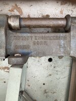
BryantHydraulic V3.jpgBryant Hydraulic Vise1.jpg

I removed the center and right side pedal to take the photo.
Bryant Hydraulic pedal base.jpg

Kinda of a neat item..

PierceA.

That's a great pickup! I've only seen a couple of others and I'm sure whatever time / material you invest in that vise, will be well worth it.

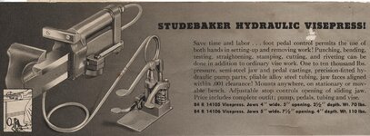
I believe your Bryant vise precedes the Studebaker hydraulic vise. The following 1941 Iron Age magazine article shares a little historical light on the two companies.


Studebaker Start Machine Firm

"Two names familiar to the automotive field have entered another branch of industry. J.M. Studebaker and his son, J.M. Studebaker, III, have formed the Studebaker Machine Co. to produce hydraulic vises, riveters and presses.

Both were until recently directors of the automotive corporation that bears their name. The new company will operate under an exclusive license with Bryant Engineering Corp., Cicero, Ill., which owns the patents on the devices to be manufactured. Sales offices will be located in Chicago and executive offices in South Bend, Ind."

1941 Iron Age - Vol.148 Pg.105


Here's a 1943 Studebaker catalog scan describing your vise in their own words.

1943_montgomery_ward_powr-kraft_cat-11a.jpg

Thanks for posting, you certainly got my attention with that vise.
 

TheRealZeus

Well-known member
Joined
Oct 4, 2021
Messages
5,012
Location
CONTINENTAL USA
Hi guys, been a long time since I posted but I only post when I find a cool vise, and I have been skunked for several years finding a noteworthy one. Then this morning...I actually completed a FB Marketplace transaction :LOL:

Lick your chops...7" Williamson :love: I've only ever seen a few examples of these, and never a 7". ANYTHING 7"+ is rare, period.

Astute readers will note that the tongue is broken out of it, but I'm a machinist and fab guy, so this will get repaired to look great and function great too. I never get upset about broken stuff...it's all part of the story when you bring it back to life.

Hope yinz like it!

US711607A​

This always helps when I can’t put my hands on it. Nice save! 👍
 

Attachments

  • IMG_4694.jpeg
    IMG_4694.jpeg
    632.2 KB · Views: 24

PierceA

Well-known member
Joined
Aug 6, 2020
Messages
471
Location
SE Michigan
Fierljeppen: THANK YOU! You always seem to find info on rare and obscure vises or tools!!

When I get the hydraulics working, it will be interesting to see how well it works.

I'm glad you find it interesting. It is a piece of vise history, and is in preservable condition.

PierceA
 

F-22

Well-known member
Joined
Jan 23, 2022
Messages
1,830
I always admire the hefty 'cheeks' on the dynamic of big US vises - but maybe that's actually a casting problem - not a foundryman myself but used to deal with them - one of the things I think I picked up was that changes in section thickness could be points of weakness - as I understand it the thinner section solidifies first then there can be porosity developing along the line where it becomes thicker and solidifies later -- line of weakness. Can counteract somewhat with good choice of feeder/riser position.

Wabbit, on a UK thread (thanks) - showed an early Chas Parker advert I never saw before with wrought iron rod reinforcements --1894 No 3 Parker Parallel Machinist 000 - 6.jpg

I assume these are cast-in, rather than a hole drilled and inserted - might be poss as I think wrought iron has a higher melting point than cast iron, but would absorb at least some carbon on its skin and also both have different coefficient of expansion - raises all sorts of questions but I guess C P tested this. Wonder how long they used it in manufacture - they're obviously seeing this as a point of weakness in other vices.

any foundry metallurgists to check my comments above?


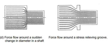
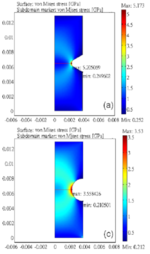
The other thing is that such a design will always fail at a geometric transition. It is where all the stress is concentrated. When you think about it, there's no reason for it to just snap in the middle of the thin section, it will always snap at its "weakest link".


stress.PNGstress2.PNG


(ignore the color and notice the "max" in the narrow V notch is 5, compared to 3.5 in the wider U notch)
 

merkyworks

Well-known member
Joined
Nov 11, 2016
Messages
587
Location
Texas
@dannyr & @F-22 yall are both right.

geometry 100% plays a role in stress concentrations but when you are dealing with castings large changes in CS and cooling/solidification is also a potential point of stress/failure.

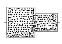
also the 1st pic F-22 shows is a forging cause the metal grain flow lines, well flow with the geometry. A casting would be more like lots of dots and evenly distributed throughout the geometry.

Example of what casting would be, not the best example but it’s late and I’ve had a few drink so this will have to do.
IMG_2021.jpeg
 
Last edited:

Grant Gunderson

Well-known member
Joined
May 17, 2013
Messages
2,330
Location
Bellingham, WA
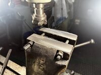
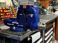
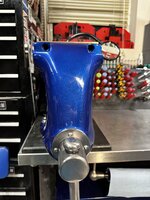
Finished up my full restoration of my Wilton C3. I machined the jaws square along with machining the anvil dead flat. I drilled the pipe jaws to take a dog point set screw to lock them in place. The rear pins got replaced with stainless set screws with hollow lock set screws. Finally I added a thrust bearing to the screw and painted it with Lumabase 3k automotive paint after I smoothed out the sand casting. Decided the vise was too tall on my work bench so ended up mounting it to a ¾” plate that’s bolted to the bench so I can always reinstall the swive base if I decide to latter.
IMG_5123.jpeg
IMG_5134.jpeg
IMG_5137.jpeg
IMG_5704.jpegIMG_5705.jpeg
IMG_5709.jpeg
IMG_5706.jpeg
 

F-22

Well-known member
Joined
Jan 23, 2022
Messages
1,830
also the 1st pic F-22 shows is a forging cause the metal grain flow lines, well flow with the geometry. A casting would be more like lots of dots and evenly distributed throughout the geometry.
For sure a casting has many more problems too... But the lines are supposed to show "force flow" when the material is stressed, not the grain of the material.
 

Mark in Indiana

Well-known member
Joined
Aug 11, 2010
Messages
3,057
Location
Southern Indiana
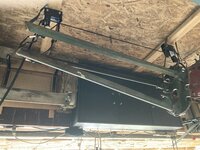
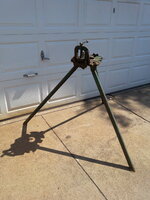
When floor space is at a premium, an unused bicycle hoist is a great way to store a trip-stand pipe vise.
This is my 100+ year old NYE try-stand pipe vise. Heavy, with a cast iron top. Saved me a lot in plumber costs over the years.
 

Attachments

  • NYE VISE IN STORAGE.jpeg
    NYE VISE IN STORAGE.jpeg
    826.3 KB · Views: 37
  • NYE PIPE VISE1.jpg
    NYE PIPE VISE1.jpg
    942.3 KB · Views: 37
  • NYE PIPE VISE4.jpg
    NYE PIPE VISE4.jpg
    972.2 KB · Views: 39

dieselsmoke

Member
Joined
Jul 25, 2013
Messages
23
Location
North of Pittsburgh PA
The other thing is that such a design will always fail at a geometric transition. It is where all the stress is concentrated. When you think about it, there's no reason for it to just snap in the middle of the thin section, it will always snap at its "weakest link".


stress.PNGstress2.PNG


(ignore the color and notice the "max" in the narrow V notch is 5, compared to 3.5 in the wider U notch)

To be more clear, I wouldn't use the term "geometric transition," I'd use the words "abrupt change in section thickness."

You can have smooth flowing transitions that handle load well, but square corners involving abruptly necked-down sections are notorious.
 

dieselsmoke

Member
Joined
Jul 25, 2013
Messages
23
Location
North of Pittsburgh PA
Dannyr and dieselsmoke: on a 4" or 5" Parker with the 'Solid Steel' insert in the slide of the dynamic, I have several of these vises, and the steel insert is usually around 3/8" high by 5/8"-3/4" wide.. And it is supposed to go all the way to the middle of the jaw tower.
The vises that I have that had cracked down the center of the top of the slide, showed a poor casting around the steel insert. In some cases there was only a 1/16"-1/32" thick layer of iron over the insert on the inside of the slide. [adjacent to the mainscrew].
On some, there were areas of several inches long that no iron was covering the insert on the inside of the slide..
I need do look, but I don't think any of my Parkers vises that have the steel insert where it is well placed and integrated with the cast iron have developed cracks..
The dynamic looks like they are poured in an upside down position. There is a 'cold joint' down the center of the mainscrew open area.
It appears that the pouring of the cast iron around the steel insert flows around each side of it. Then it is supposed to cover the insert and then join together as a flowing, molten liquid iron fully encapsulating the insert. But maybe the steel cools the molten iron too much and stops the flow?

PierceA.

You're thinking the right way.

The insert piece has to have a gap around it so that the cast metal can flow around it and carry heat in there. Ideally, one would put a "lump" around this area and then later machine it off. That would make sure you have plenty of hot metal flowing around the insert to get it hot and keep metal moving around it, giving it time for carbon diffusion and integration with the casting.

This gets back to what I said before about finding a way to support the insert in space while pouring. If you can afford to put a hole in whatever object you are making, you can use a small sand core to support the insert and hold it in place. If you can't afford a hole, you're stuck with cantilevering it out, or using a fine metal chaplet that hopefully melts itself and disappears right after the casting skins over enough to hold the insert. It's a game of time and heat.

I'm sure people with enough commitment to making it work would have figured out that having it preheated and very clean would certainly help, and for example, heating the insert and then at the last minute drop it into the mold and then close the mold as fast as you can while the ladle is there ready to pour.

Many many castings have been ruined by "core shift" where a sand core (or say this insert) is supposed to be precisely gapped in its air space between several mold walls. Well, in production, people hurry and stuff sags or wiggles loose. Maybe even due to metal flowing forces, but usually it's a poor design where the core has such flimsy support that it lays over toward a wall just due to gravity. That gives you a thin wall on that side, and until someone breaks it, it's hard to know how well you did.

A famous example of this is the Brazilian-cast 12 valve Cummins engines, called the "53 Block". Many of them had the core for the water jacket slip or float or whatever toward the outside of the block. In the stock state most of them were fine, but start adding power and the blocks cracked right down the side, freeing the coolant to quickly exit :oops:
 

neophyte

Well-known member
Joined
Apr 23, 2012
Messages
9,767
Location
Pennsylvannia
Watco dries Faster than BLO because as Smitty pointed out, it is BLO
.....but it contains a drier, some sort of drying agent.
Probably Japan Drier

I wipe the Watco on the old vises and they are dry tomorrow
After an overnight drying session, the finish does not wipe off nor is the finish unstable in any way
The oil puts a nice seal on the metal, kind of like it does to wood.

Over the course of time, layers of Watco puts a beautiful finish on wood. I use it on our furniture, certain gunstocks, speaker cabinets, etc often with a light 0000 steel wool in between coats
Gorgeous
It also looks great on those old vises that I have in the shop
jd.jpg
Maybe try a bit of Japan Drier with your BLO to make it dry faster
Technically, all “Boiled Linseed Oils” contain a drying agent.
It’s literally the definition of what “Boiled Linseed Oil” is.
BLO isn’t “boiled”.
BLO has metallic compounds added that act as drying agents.
Traditionally the drying agent used in Boiled Linseed Oil was lead white, but that is no longer legally allowed to be used for commercial purposes in the USA, at least for common household paints and finishes.
You can still purchase lead white as a high end specialty art and restoration supply.
Watco Danish Oil is likely partially polymerized by heat treating the oil.
Current “Japan Driers” are all over the place as far as ingredients.
Heat or UV lights would cause the Oil finish to dry quicker.
 

FullRaceMerc

Well-known member
Joined
Jan 9, 2015
Messages
3,869
Location
SoCal (SGV)
When floor space is at a premium, an unused bicycle hoist is a great way to store a trip-stand pipe vise.
This is my 100+ year old NYE try-stand pipe vise. Heavy, with a cast iron top. Saved me a lot in plumber costs over the years.
Very cool vise & creative storage solution. (y)

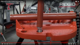
Gotta ask, are you familiar with the purpose of the threaded piece with the handle below the top?
 

Mark in Indiana

Well-known member
Joined
Aug 11, 2010
Messages
3,057
Location
Southern Indiana
Very cool vise & creative storage solution. (y)

Gotta ask, are you familiar with the purpose of the threaded piece with the handle below the top?
The threaded piece is a jack screw for a ceiling brace to add stability. You place a length of 1" pipe between the end of the jack screw and an overhead beam, jack the screw up.
 

Attachments

  • Screenshot 2023-08-18 at 9.58.40 AM.png
    Screenshot 2023-08-18 at 9.58.40 AM.png
    2 MB · Views: 58

FullRaceMerc

Well-known member
Joined
Jan 9, 2015
Messages
3,869
Location
SoCal (SGV)
The threaded piece is a jack screw for a ceiling brace to add stability. You place a length of 1" pipe between the end of the jack screw and an overhead beam, jack the screw up.
I learned that in my early 20s, while I was a helper for an old plumber. I've asked that same question many times in the years since, & you are the first guy in 40 years to know the correct answer. Asking on GJ I figured the odds would be better.
 

Mark in Indiana

Well-known member
Joined
Aug 11, 2010
Messages
3,057
Location
Southern Indiana
I learned that in my early 20s, while I was a helper for an old plumber. I've asked that same question many times in the years since, & you are the first guy in 40 years to know the correct answer. Asking on GJ I figured the odds would be better.
I had to look up the Jack screw myself a few years ago. I‘ve sold a few Ridgid tri-stand vises with them. Wanted to be sure I had all the information for the customers. BTW: If you’re interested, there are plenty of interesting YouTube videos on tri-stand pipe vise uses.
 
To avoid these ads, REGISTER NOW!
Top Bottom