To avoid these ads, REGISTER NOW!

Above 1200 Sq/FT The Action Sports Garage

Wokspaces above 1200 squarefeet.
OP
G

Grant Gunderson

Well-known member
Joined
May 17, 2013
Messages
2,325
Location
Bellingham, WA
IMG_4842.jpegIMG_5684.jpeg
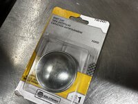
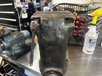
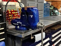
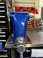
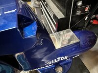
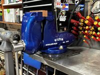
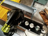
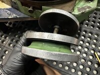
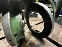
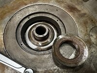
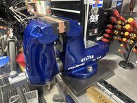
The vise was missing the rear dust cap so I picked up one for a Ford from napa
IMG_5686.jpeg
A cup out of a ball joint press works as a driver to install it
IMG_5689.jpeg
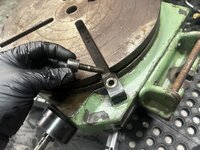
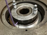
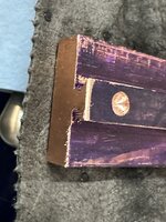
I then blued the edge of the pipe jaws and used a transfer punch to mark the location of where the set screw holds them in place
IMG_5692.jpeg
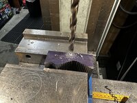
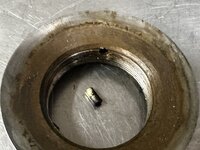
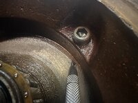
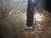
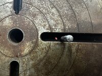
I then drilled a hole to retain the set screws to better lock them in place. These hardened jaws where a ***** to drill!
IMG_5694.jpeg
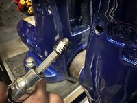
They now get retained by a dog point set screw with some tefgel on it.
IMG_5695.jpeg
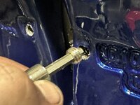
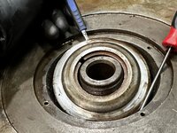
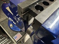
And then locked in place with a hollow-lock set screw. All that’s left is to machine new jaws.

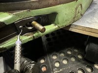
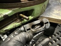
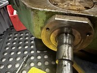
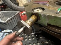
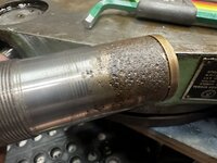
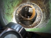
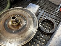
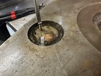
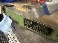
Here is the before picsIMG_4840.jpegIMG_4844.jpeg
 
To avoid these ads, REGISTER NOW!
OP
G

Grant Gunderson

Well-known member
Joined
May 17, 2013
Messages
2,325
Location
Bellingham, WA
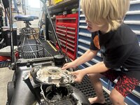
My brother showed up with his broken Honda lawn mower. With all of the forest fire smoke I thought it was a good inside activity to work on with my 6 year old son.

IMG_5766.jpeg
I let him do all of the work with some help / supervision from dad
IMG_5811.jpeg
IMG_5783.jpeg
It was good to see that he was curious about it

IMG_5791.jpeg

Found the problem. One of the pivots for the valves was fully unscrewed laying in the bottom of the engine.
IMG_5795.jpeg

IMG_5801.jpeg
He fished it out for me.


Cleaned up the pivot with a file addedIMG_5804.jpeg

IMG_5827.jpeg
And he put it all back together. Fired up first pull too! My brother was happy, Stian felt a sense of accomplishment and I’m a proud dad!
 

Attachments

  • IMG_5790.jpeg
    IMG_5790.jpeg
    435.7 KB · Views: 5
  • IMG_5795.jpeg
    IMG_5795.jpeg
    556.6 KB · Views: 8
OP
G

Grant Gunderson

Well-known member
Joined
May 17, 2013
Messages
2,325
Location
Bellingham, WA
IMG_5846.jpeg
To finish his education in power mechanics for the day I took him to see the monster trucks.
IMG_5883.jpeg
Ponied up for the monster truck ride for him too. Ws worth every cent of the $10 to see how excited he was.
IMG_5899.jpeg
He says he’s ready to drive it!
IMG_5855.jpeg
Pretty sure he could drive it as well as that driver. I’m willing to bet the guy driving it had more than a few wobbly pops before giving the kids rides.
IMG_5913.jpeg
Monster trucks and dinosaurs tearing apart cars. What more could a kid want!
IMG_5465.jpeg
Back to bikes. His 20” Commencal didn’t come with a chain guide. Mind boggling it didn’t given the cost. What’s even more F’d is a chain guide these days is $100. I must have thrown 20 of them away last time I cleaned out my bike parts boxes.
IMG_5719.jpeg
Despite a pretty good collection of BB tools didn’t have one that fit the bottom bracket on his bike. It’s a 30mm 12 notch. Damn bike industry and it’s “standards”. And of course there is now a 30mm 12 notch and a 16 notch standard too
IMG_5723.jpeg
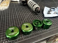
So ended up ordering 4 more BB sockets from Abbey. I should now have all of the mountian versions out now.
IMG_5716.jpeg
I like how Abbey engraves the torque specs. Just wish they would do it in N/M as well.
IMG_5721.jpeg
Added some Tef-Gel to the threads prior to reinstalling it.
 
OP
G

Grant Gunderson

Well-known member
Joined
May 17, 2013
Messages
2,325
Location
Bellingham, WA
IMG_5722.jpeg
I’m really liking these fluid syringes for use as grease application and for fork oil. The caps are nice as it keeps them from leaking. IMG_5725.jpeg
Hopefully no more dropped chains for him.
IMG_5728.jpeg
I snapped a spoke on the front wheel of the e-bike. It’s so loose out right now I couldn’t slow down on a steep decent and slammed into a catch berm that then got relocated into the forest. First step is to remove the rotor. I have converted to only using my Festool impact driver for this. It saves so much time.
IMG_5729.jpeg
My knipex bolt cutters make quit work of cutting the broken spoke out.
IMG_5731.jpeg
Instead of replacing all of the rim tape I just cut out the section where needed
IMG_5732.jpeg
New spoke and ****** installed. Anytime I get a new wheel set I always have a handful of extra spokes cut. It’s not if but when a spoke will need to get replaced.
IMG_5733.jpeg
I normally use 1” gorilla tape as it’s way better when standard rim tape but I was out of it. So used some DT Swiss stuff I had laying around. Tried up the wheel and it’s good to go.
IMG_5515.jpeg
Finished the day taking the kid cliff jumping.
IMG_5528.jpeg
After the first jump with dad there was no stopping him from doing it a bunch of times solo. He’s hooked on it.
 
OP
G

Grant Gunderson

Well-known member
Joined
May 17, 2013
Messages
2,325
Location
Bellingham, WA
I’ve been noticing a lot of play the the e-bike suspension. I got it narrowed down to the lower pivot.
IMG_5944.jpeg
I normally like to wash my bike before working on it but was in a hurry to get it resolved to take the kid out for a tow. The pivot can easily be removed from the non drive side.
IMG_5970.jpeg
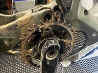
Notice the wear on the shaft. Good sign that a bearing is bad. Unfortunately you need to remove the front right sprocket for access.
IMG_5946.jpeg
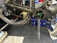
On a Shimano steps motor you remove the crank first. Then to get the lock ring off it’s best done with the rear wheel on as you need hold it in order to remove the lock ring. The lock ring is left handed thread. The new Abbey Steps BB tool is way better than the Park one I had previously as it mounts directly to a ⅜ ratchet without having to use a socket.
IMG_5948.jpeg
The Abbey tool has really good engagement on the lock ring.
IMG_5952.jpeg
In order to get the bearings out, you could use a blind bearing puller. However the better way is to push the internal spacer so it’s off set to one side. Then press out using a drift
IMG_5950.jpeg
The Park suspension bearing drift set is really nice for this and covers damn near every bike bearing out there. However their press *****. So as I described early in this thread I modified an Abbey press to use an 8mm trapezoid screw that will work with the Park tools 8mm on all of their drifts.
In this case I selected a drift that fits inside of the bearing and then a cup large enough to catch the bearing being pressed out.
IMG_5954.jpeg
That was quick and easy.
IMG_5955.jpeg
The Repeater uses a 6903 bearing here.
IMG_5958.jpeg
Fresh water proof grease gets added to the side receiving the first bearing.
IMG_5961.jpeg
Here is the setup to press the first bearing in. The large drift fits into the bearing counter bore on the other side of the frame. This ensures you press the new bearing in square. The small drift fits into the bearing being pressed in holding it perfectly in align.
 
OP
G

Grant Gunderson

Well-known member
Joined
May 17, 2013
Messages
2,325
Location
Bellingham, WA
IMG_5962.jpeg
IMG_5965.jpeg
The internal bearing spacer gets a liberal amount of water proof grease and inserted.
IMG_5966.jpeg
To press the second bearing in I select a drift that fits inside of the bearing to hold everything in alignment. The smaller drift fits into the second bearing holding it in alignment.
IMG_5975.jpeg
Everything gets put back together and the motor lock ring gets torqued using the Abbey socket. It’s important to not over torque as you don’t want to damage the motors clutch.
 
OP
G

Grant Gunderson

Well-known member
Joined
May 17, 2013
Messages
2,325
Location
Bellingham, WA
IMG_6060.jpegWas planing on working on the jaws for the Wilton today, but got a call from a buddy who was desperate to get his DVO shock running.IMG_6052.jpeg

Supposedly it was just rebuilt by the guy he got it from….ok I bet we will find some surprises.
IMG_6053.jpeg
First step is to remove the valve core from both the main shock body and the revisor bladder.
Then compress the revisor piston and remove the lock ring. Pretty standard stuff
IMG_6054.jpeg
Since I don’t own a DVO valve puller I just used a Schraeder inflator to pull the piston out
IMG_6055.jpeg
The rubber bladder just pulls off of the resivor piston.
IMG_6056.jpeg
The shaft eyelit gets clamped in the vise soft jaws. Then the piston head unscrews with an 18mm low torque wrench
IMG_6057.jpeg
Let it drain while I drink one of his beers IMG_6058.jpeg
Upper eyelit gets clamped in the soft jaws and the resivor unscrews
IMG_6060.jpeg
The lock out valve just pops out of the end of the resivor body. All the lockout does is control fluid movement in and out of the reservoir
IMG_6064.jpeg
The main shaft gets clamped into the 10mm shaft clamps and the head unscrews. I can’t wait to finish the Jaw project
IMG_6065.jpeg
Main components laid out. Other than removing the green rebound shaft this is all you have to do to get to all of the seals. I did pull the compression shin stack apart to clean it. It’s dead simple. Just 3 shins in a pyramid stack and a single check valve shim. The Fox and Rock Shocks stuff is light years more advanced in the shimming and especially in the seals.
 
OP
G

Grant Gunderson

Well-known member
Joined
May 17, 2013
Messages
2,325
Location
Bellingham, WA
IMG_6070.jpeg
The shin stack is easy to get to by removing the nut on the main shaft with a 11mm socket. DVO doesn’t provide torque specs. So tighten it till it snaps then back it off a ¼ turn. IMG_6068.jpegThe inner seal on the main piston that slides in the main shaft is what had failed. They just use a stanadard rectangle oring here with no backup rings unlike other brands.
IMG_6073.jpeg
This is the rebound valve. As it rotates it controls how much fluid moves through the holes cross drilled in it. Just 3 simple o rings. The spring and metal ring is for the ball detent. It’s *** backwards of every other ball detent out there
IMG_6075.jpeg
The lock out valve has a very tiny hole drilled in it as a bypass. Bet it doesn’t work. It’s just one fat o-ring sealing it. I’d strongly suggest never locking it out.
IMG_6076.jpeg
With fresh seals it all gets torqued back up.
My hands were pretty oily at this point so didn’t take any pics but the one. One nice thing is the bleed adapter is a Standard Reverb bleed adapter so you can just use a Reverb bleed syringe to bleed it.
 
Last edited:

rbkool

Active member
Joined
Jul 9, 2015
Messages
33
Location
Calgary, Alberta
Interesting take on the DVO shock. I have one on my 2019 Giant Trance Advanced Pro 0, and at the time DVO was thought to be one of the best/unique suspension companies in the market. The fact that I don't see them spec'ed on (very) many current OEM builds probably tells me what I need to know, but I assume based on that last job that you also don't have a high opinion of their quality/durability?
 
OP
G

Grant Gunderson

Well-known member
Joined
May 17, 2013
Messages
2,325
Location
Bellingham, WA
Interesting take on the DVO shock. I have one on my 2019 Giant Trance Advanced Pro 0, and at the time DVO was thought to be one of the best/unique suspension companies in the market. The fact that I don't see them spec'ed on (very) many current OEM builds probably tells me what I need to know, but I assume based on that last job that you also don't have a high opinion of their quality/durability?
They are very easy to service which is good, because the seals are not very good or well thought out in their implementation. Plus the dampening shims and rebound adjustments are way behind what Fox and Rock Shocks are doing in my mind the build quality just isnt there. For the price I’d take any other offering over theirs.
 

trytochaseme

Well-known member
Joined
Sep 3, 2014
Messages
447
Location
616 in the Mitten
I had a diamond that had a custom tune on it from DVO and that was my favorite fork ever, it was so damn plush. Ive had a few Jade rear shocks and been super happy with those as well. I do have another Diamond now and its a little meh, not as great as my last one and I have heard about issues with quality control and stuff with them over last couple years.
 
OP
G

Grant Gunderson

Well-known member
Joined
May 17, 2013
Messages
2,325
Location
Bellingham, WA
I ended up seeing a Brideport mill on the local craigslist. Figured I'd go have a look.IMG_6181.jpeg

This machine was tiny! It had a super small 32" table and with that old non-R8 head on it, it felt like a toy. Despite the surface rust, the ways were in EXCELLENT shape! If it had a normal sized table on it, I would have bought it for a restoration and swapped the heads with mine. Price was right too. I passed on the mill and asked the guy what else he had for tooling.
IMG_6184.jpeg
Turns out, he had a rotary table. Ive been trying to find one in decent shape since I bought my mill and for a reasonable price.
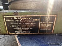
IMG_6185.jpeg
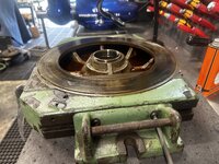
This table is a monster. 15". I couldn't imagine using it on that tiny machine. I asked him how much he wanted and when he said $100 I couldn't get my wallet out fast enough.
IMG_6201.jpeg
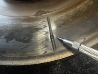
The table is in great shape with only one apprentice mark in it. Fro the price I can live with that.
IMG_6205.jpeg
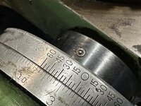
Dials are in decent shape and I bet they will clean up nicely too.
IMG_6208.jpeg
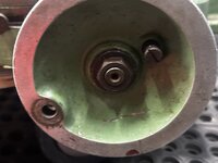
Only major issue is its missing the handle. I'm pretty sure I have on in my pile of parts that will fit. This Table is un godly heavy. It's at least 200Lbs. It's low profile which is nice so it doesn't eat up too much Z-axis on the mill either. Evidently, Bridgeport made an adapter to use it Vertically as well. I believe they even made an index attachment and tail stock for it too, but sadly I dont have any of those. I think I'll make do.
IMG_6213.jpeg

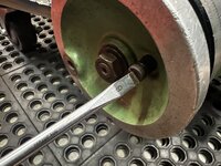
The locking screw for the dial was stuck, so I used a #6 hollow ground drive to remove it.

IMG_6215.jpeg
Note there is a flat washer on it.

IMG_6217.jpeg
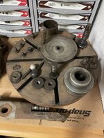
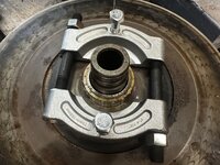
Before I put any new-old tool to use in my home shop I want to get it up to my standard. So first things first is a full tear down and rebuild.
I couldn't find much in the way for information on tearing this apart, other than a parts diagram online and lots of people talking about them leaking oil. First step, is to use a brass drift to hold the handle steady and a 15/16" socket to remove the main nut on the handle.
IMG_6222.jpeg
There is a large flat washer behind the nut.
 
OP
G

Grant Gunderson

Well-known member
Joined
May 17, 2013
Messages
2,325
Location
Bellingham, WA
IMG_6224.jpeg
The handle assembly then slides off of the main screw shaft. It rides on a Woodruff Key #5
IMG_6225.jpeg
Here you can see the wedge that locks the dial in place.
IMG_6231.jpeg
I then tried to tap the woodruff key out.
IMG_6233.jpeg
Even tried a bit of heat too.
IMG_6235.jpeg
Damn thing wont budge no matter where I tap on it. So I soaked it with some Kroil and will come back to it.
IMG_6238.jpeg
Before I remove the Vernier Dial, I placed a small witness mark with a scribe on the back of it inline with the ball oiler.
IMG_6243.jpeg
I added one to the front to mark is relation to the inner sleeve as well. You can see that woodruff key is a bit mangled from trying to tap it out.
IMG_6241.jpeg
The Vernier Dial is held in place by two countersunk screws.
IMG_6245.jpeg
There was a bit of swarf / crud back in there. Before I move any farther along with removing the main screw shaft, I need to flip the table over. Before I do that, I need to finish stripping the top side.
IMG_6249.jpeg
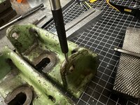
The levers to the table locks have a small hole drilled into them that aids in their removal. Just slide a long pin punch in and use it to break them free.
 
To avoid these ads, REGISTER NOW!
OP
G

Grant Gunderson

Well-known member
Joined
May 17, 2013
Messages
2,325
Location
Bellingham, WA
IMG_6250.jpeg
The lock bolts unthread
IMG_6253.jpeg
Under each lock bracket is a roll pin that keeps the lock bracket aligned to the table.
IMG_6255.jpeg
On the back of the table the handle for the engagement lever just unthreads.
IMG_6259.jpeg
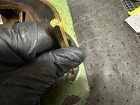
I used a dental pick to clean the crud out of the screw heads so I dont strip them.
IMG_6263.jpeg
The engagement plate is just held on by two screws. The engagement lever is clearly threaded into a cylinder. I couldn't get it to budge by hand. I suspect there is a set screw from the bottom holding it in. I dont want to force it.
IMG_6267.jpeg
On the front of the table the zero plate is held in place by the Zero binder screw. Its clearly bent, and didnt want to unscrew.
IMG_6266.jpeg
I was able to get it out with some soft jaw pliers.
IMG_6270.jpeg
I haven't checked it yet, but I bet thats a standard ¼-20 thread. I can probably source a new thumbscrew from McMaster or whenever I finish my Monarch 10EE rebuild I can just make one.
IMG_6273.jpeg
The handles for the table are designed to be removed, to fit Bridgeports Vertical adapter. They are just held in place by two SHCS. For now I am only removing the Right side one, so I can use the left side to tilt the table up and then place it upside down. Its damn heavy, so I want to use leverage to my advantage.
IMG_6276.jpeg
They keyway for the handle is filthy.
 
OP
G

Grant Gunderson

Well-known member
Joined
May 17, 2013
Messages
2,325
Location
Bellingham, WA
IMG_6283.jpeg
With the table flipped over I can now work on removing the access covers and see what I have to work with.
The main pivot has a circular cover that surrounds it thats held in place by 4 countersunk screws
IMG_6285.jpeg
With the screws all out, I was able to lift the cover by sliding a 90ø pick into one of the screw holes.
IMG_6286.jpeg
Looks like a bunch of dried out caked on way oil. Looks to me that there should be a gasket along the outer edge of that ring to keep oil from leaking. I'm missing one here.
IMG_6373.jpeg
On the inner edge of that ring, there is an O-ring hiding in it. I removed it using a brass o-ring tool.
IMG_6375.jpeg
I'm thinking about replacing it with a Quattro seal style o-ring.
IMG_6291.jpeg
Moving along, the main locknut has a set screw in the side that locks it in place.
IMG_6292.jpeg
With the set score out, I then sized the pin holes in the lock ring for my Facom adjustable pin spanner.
IMG_6294.jpeg
A couple of light taps with a brass hammer got the lock nut free
IMG_6297.jpeg
more crud from dried up way oil. Notice the bevel on the underside of the lock ring.
IMG_6299.jpeg
The setscrew I removed earlier, pressed on a brass plug that lock the ring inlace without damaging the fine threads.
 
OP
G

Grant Gunderson

Well-known member
Joined
May 17, 2013
Messages
2,325
Location
Bellingham, WA
IMG_6300.jpeg
I removed it using a pin punch.
IMG_6305.jpeg
I used a plunger tool and a 90ø pick to left the thrust race out of the cavity.
IMG_6308.jpeg
There is a roll pin in the main pivot shaft that is blocking access to remove the next lock ring.
IMG_6309.jpeg
I attempted to remove it with some screw removal pliers.
IMG_6311.jpeg
IT ended up breaking into. Luckily I have full set of these on hand. I'm now stuck for a bit with removing the next lock nut. It is recessed too deep for any of my pin spanners to reach. So I ordered a Glad nut wrench, that will hopefully arrive tomorrow and work. IF not I will just machine up a custom pin spanner for this. Moving on to what I can work on tonight.
IMG_6315.jpeg
There are two round access plates that cover access to one end of the main screw shaft and the other covers access to the Enagement selector. The rare each held in place by 4 countersunk screws. With the screws out, I couldn't budge the plates. I have them a good soak of Kroil and moved on.
IMG_6317.jpeg
The main screw shaft thrust bearing cover is held in place by 3 SHCS
IMG_6319.jpeg
With those out I used a brass punch to tap it off
IMG_6326.jpeg
Note, the oil passage from the ball oiler to the thrust bearing. ITs all very well machined.
IMG_6328.jpeg
The thrust bearing lock nut is held in place by a set screw.
 
OP
G

Grant Gunderson

Well-known member
Joined
May 17, 2013
Messages
2,325
Location
Bellingham, WA
IMG_6332.jpeg
The setscrew pushes against a brass key that locks the threads in place without damaging them.
IMG_6333.jpeg
I then used a Spudger tool to get the thrust bearing off of the shaft. Notice the notch in the rear portion of the thrust bearing.
IMG_6336.jpeg
The inner face of the thrust plate is b beveled to match the concave bevel on the brass portion.
IMG_6338.jpeg
Notice what looks to be a key way cut into the main screw shaft. I believe this and the notch in the brass piece above is part of the oil passage from the ball oiler.
IMG_6345.jpeg
Moving back to the access plates, I still couldn't get them to budge, so I heated them up with a blow torch until the Kroil started to bubble back up.
IMG_6339.jpeg
I then used a brass punch and hammer to tap them in a counter clockwise direction and this got them freed right up.
IMG_6347.jpeg
Looking at the rear cover of the selector portion there was definitely some sort of sealer used to keep oil from leaking. I bet there should be a gasket here.
IMG_6343.jpeg
Same with the front. Looks like RTV, but I think Ill probably cut a custom gasket when I replace it.
IMG_6344.jpeg
I found a set screw under the front cover. The center hole I think is from machining the piece on a lathe.
IMG_6352.jpeg
With the set screw out, I then attempted to turn the front bushing that retains the screw shaft. I ended up using some scrap copper to protect it, and a large pipe wrench to get it broken free. It didnt take too much effort with a 2.5 foot pipe wrench to free it.
 
OP
G

Grant Gunderson

Well-known member
Joined
May 17, 2013
Messages
2,325
Location
Bellingham, WA
IMG_6354.jpeg
I was then able to fully unscrew it using a strap wrench.
IMG_6356.jpeg
IMG_6358.jpeg
The threads appear to be in great shape. Somehow there was some swarf in there that was probably causing it to bind a bit.
IMG_6359.jpeg
The bushing is sleeved with a bronze insert.
IMG_6360.jpeg
Notice the crud embedded onto the outer section of the rear of the bushing. Luckily this is not a bearing surface!
IMG_6362.jpeg
The main screw shaft could then be screwed out. It appears to be in very good shape.
IMG_6364.jpeg
The bushing nut took a light tap with a brass drift to get it moving.
IMG_6365.jpeg
The threads look to be in great shape. Once again the set screw pushed on a brass plug that protects the threads.
IMG_6367.jpeg
The inner abyss has a bunch of gunk in it, but the gear appears to be in good shape from first inspection.
IMG_6349.jpeg
On the rear adjuster pivot I scribed some witness marks. I then tried to locate a set screw in the same hole the front bushing nut had. Its so full of gunk I couldn't find one, so I left it to soak overnight in solvent.
 

SilverJimmy

Well-known member
Joined
Apr 14, 2012
Messages
1,643
Location
Prescott/Flagstaff, AZ
I’ll be watching this one closely as I picked up a Troyke 15” Rotary Table a few years ago. It had been disassembled by the previous owner and then sold to me when he decided it was a bigger project than he thought. Interesting how different two things that are designed to do one thing the same (rotational movement) were designed and made! My table has definitely more apprentice scars than yours. I’m thinking a competent flywheel grinder operator would be able to clean mine up and then I just need to recut the dividing lines on my mill.
F74D3B1F-6B08-49C0-92A0-32F3527D04F2.jpeg
85C80B5D-4A71-4E0D-B98C-E13A42EA5C9D.jpeg
702501DD-FB48-4BB1-8EEA-D78C74A25055.jpegEECF47BE-AD13-4CB2-9DD5-0F0F67B0F762.jpegIt was cool that I was actually able to call Troyke and talk to guy who has worked there for years and he emailed me manuals and drawings for my rotary table! And you are correct, these things are HEAVY! Even apart, every part weighs a ton!
 
OP
G

Grant Gunderson

Well-known member
Joined
May 17, 2013
Messages
2,325
Location
Bellingham, WA
I’ll be watching this one closely as I picked up a Troyke 15” Rotary Table a few years ago. It had been disassembled by the previous owner and then sold to me when he decided it was a bigger project than he thought. Interesting how different two things that are designed to do one thing the same (rotational movement) were designed and made! My table has definitely more apprentice scars than yours. I’m thinking a competent flywheel grinder operator would be able to clean mine up and then I just need to recut the dividing lines on my mill.
F74D3B1F-6B08-49C0-92A0-32F3527D04F2.jpeg
85C80B5D-4A71-4E0D-B98C-E13A42EA5C9D.jpeg
702501DD-FB48-4BB1-8EEA-D78C74A25055.jpegEECF47BE-AD13-4CB2-9DD5-0F0F67B0F762.jpegIt was cool that I was actually able to call Troyke and talk to guy who has worked there for years and he emailed me manuals and drawings for my rotary table! And you are correct, these things are HEAVY! Even apart, every part weighs a ton!
Those Troykes are supposed to be really nice! I bet that will clean up nicely.
 
OP
G

Grant Gunderson

Well-known member
Joined
May 17, 2013
Messages
2,325
Location
Bellingham, WA
IMG_6389.jpeg
I ordered both a small and large gland nut wrench. Unfortunately neither fit into the bore.
IMG_6390.jpeg
I typically avoid cheap sockets like the plague. However sometimes a $15 socket is the best option. This lug nut socket would be perfect but it’s got 6 pins.
IMG_6393.jpeg
A ½” carbide end mill quickly fixed that problem.
IMG_6394.jpeg
$15 and 5 minutes on the Bridgeport and I have a dedicated tool for the job. Hell of a lot quicker than making a custom tool for the job and cheaper if you factored in my time….even at half of minimum wage.
IMG_6396.jpeg
It’s a perfect fit. It didn’t take much with the 1/2” breaker bar to get the lock nut freed up.
IMG_6397.jpeg
Notice the machined inner lip of the locknut.
IMG_6399.jpeg
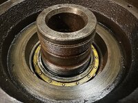
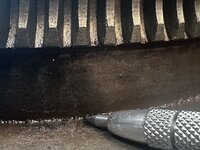
That’s a nice bearing in there!
IMG_6401.jpeg
With the table supported by some 4x6 blocks I used a brass hammer to tap on the main spindle shaft. It didn’t take much to get the table to drop out. Normally I would only press items in and out when it comes to bearings, but this won’t fit in my large #3-½ FAMco arbor press and I can’t lift it up there by my self either.
IMG_6406.jpeg
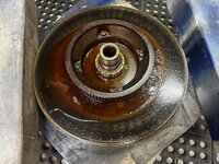
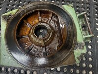
That’s some nice flaking! You can better see the roller bearing now and its brass cage. I’ll get in cleaned up and make sure the oil passages are all cleaned out.
IMG_6405.jpeg
The base casting is full of old partially solidified way oil. It’s all going to need a good cleaning. More to come.
 
Last edited:
OP
G

Grant Gunderson

Well-known member
Joined
May 17, 2013
Messages
2,325
Location
Bellingham, WA
IMG_6412.jpeg
The oil passage for the table from the ball oiler terminates here. It will need to get cleaned out as it’s fully clogged
IMG_6415.jpeg
The other ball oiler terminates here under the moan bearing. I can’t see if it’s clogged but assume it is. In order to gain access I’ll need to remove the bearing.
IMG_6418.jpeg
First I need to remove the ring gear. I made a witness mark on the side in line with the oiler.
IMG_6419.jpeg
I added a second wet of witness marks with the carbide slide on the inside of the gear ring here
IMG_6421.jpeg
I then removed the 4 SHCS holding it on.
IMG_6423.jpeg
It would t budge. Flipping the table over I noticed a hole next to two of the screw holes…. Had no idea they were there. Cleaned them out with a pick
IMG_6425.jpeg
With the table supported in 4x6 blocks I used a pin punch through the hole on either side to tap the ring off
IMG_6427.jpeg
It appears they used some sealant under the ring.
IMG_6428.jpeg
No wonder it wouldn’t budge!
IMG_6431.jpeg
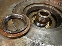
I finally have access to use my large bearing separator to remove the angular contact bearing from the shaft.
 
OP
G

Grant Gunderson

Well-known member
Joined
May 17, 2013
Messages
2,325
Location
Bellingham, WA
IMG_6432.jpeg
The bearing is a made in the USA Normal 104 BMRT. It is ungodly expensive to replace. In fact that single bearing costs more than the entire spindle bearing set I just replaced in my Bridgeport! Thankfully it appears to be in good shape.
IMG_6434.jpeg

I then turned my attention back to stripping down the base casting. I find it odd that the Right hand handle Bracker uses SHCS with different sized hex drivers then the left...
IMG_6436.jpeg
After inspecting the bracket for any signs of set screws holding the handle in and not finding any, I proceeded to press the handle out with a pin punch on my arbor press
IMG_6438.jpeg
It pressed out with ease, but I did hear a pop....WTF? Inspecting the shaft I found a small roll pin was in there.
IMG_6439.jpeg
Here is the pin hole I missed when I was looking for it.
IMG_6442.jpeg
I drove the remains of it out using a pin punch. Armed with this information I removed it from the other bracket before pressing its handle out.
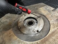
IMG_6444.jpeg
I then used a roll pin punch (see the specially shipped tip) to punch out the roll pins for location the clamp brackets.
IMG_6445.jpeg
I could have left these in, but this will make cleaning / painting easier, plus I have a full assortment of them on hand.
IMG_6447.jpeg
The long soak in Kroil did its trick, and I was able to get the selector shaft out without too much trouble.
IMG_6448.jpeg
Note, the pointed in goes back in first. Also the hole I had assumed had a set screw in it, did not have one.
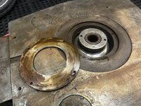
 
OP
G

Grant Gunderson

Well-known member
Joined
May 17, 2013
Messages
2,325
Location
Bellingham, WA
IMG_6454.jpeg
I then used what I had assumed to be a set hole screw, to thread in a 10-32 screw.
IMG_6455.jpeg
I then used this screw to rotate and pull up on the bushing.
IMG_6458.jpeg
That technique worked really well to free it.
IMG_6459.jpeg
Its in good shape, just covered in crud.
IMG_6463.jpeg
Then used the arbor press and a brass punch to press out the bronze inner bushing.
IMG_6464.jpeg
The non-concentric layout of it, is what allows the selector lever to engage / disengage the main screw shaft from the gear ring. I then placed all of the small parts into my ultrasonic cleaner and put all of the really rusty stuff into a bucket of evaporated-rust
IMG_6478.jpeg
A old photo paper development tray does a good job for containing all of the small parts.
IMG_6466.jpeg
I then used a thin putty knife behind the tag on the table to get the drive screws holding it in loosened up
IMG_6468.jpeg
That then allowed me to use my smallest screw removal pliers to pull the drive screws out.
IMG_6469.jpeg
Tag is off and the table is now fully stripped!
 

trojandj

Well-known member
Joined
Nov 6, 2011
Messages
45
Great, thanks Grant …. Now I feel bad acquiring a tool and using it. Might be the kick in the pants I need to clean up Grandpas drill press though.

Thanks for bringing us along.
 
OP
G

Grant Gunderson

Well-known member
Joined
May 17, 2013
Messages
2,325
Location
Bellingham, WA
I need to get the soft jaws done on the vise so I can get the woodruff key out of the shaft on. The rotary table. I’m going to make a dovetail interchangeable jaw system for the Wilton C3

IMG_6081.jpeg
I started with rough cutting some steal key stock down to size
IMG_6091.jpeg
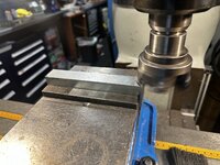
I then used a 3” face mill to square it up and machined the height of the dovetail basses, copper soft jaws and the hardened steel jaws to the same height
IMG_6095.jpeg
IMG_6103.jpeg
That’s some expensive chips….
IMG_6161.jpeg
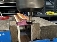
I then rough cut the center / edges of the dovetails with and end mill. By using two different heights of parallels in the mill I was able to get the depth of cut’s exactly the same on all of the pieces.
IMG_6162.jpeg
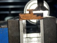
I then used a dovetail cutter to cut the dovetails. This was a bit tricky. In order for this to work with my existing shaft clamps I had to use a ½” 45 degree cutter for the main cut in the steel bases. This had to be cut in a single pass.
IMG_6187.jpeg
I set the machine to the max spindle speed and the slowest feed possible on the table. Added a bunch of cutting fluid and crossed my fingers. An hour latter I had one of the dove tail bases cut. Thankfully I got both finished without breaking th cutter!
IMG_6198.jpeg
I then needed to machine the undercut in the jaws for the matching dovetail. I could have done this with an ⅛” endmill vertically, but a woodruff key cutter is more ridged and less likely to break so I used that.
IMG_6313.jpeg
I then used a 1” 45 degree dovetail cutter to cut the corresponding dovetails. A trick I used to line up the cutter was to back light the work piece then stair straight down it to line it up. If you can see any sides to the work piece then you know you are. It looking at it square. Ie in this photo the camera isn’t facing it totally square on. Since I machines the various jaws by just changing the parrallells in the vise once this was set I could just flip and repeat the cut for all of the pieces changing out the parallels for shorter ones for the thicker pieces.
IMG_6471.jpeg
I then used some dychem blueing fluid to check the fit of the jaws into to the bases. You can see here where I have some high spots. I used carrying corses of emery paper on a glass work surface to lap the matting surfaces smooth and polished.
 
OP
G

Grant Gunderson

Well-known member
Joined
May 17, 2013
Messages
2,325
Location
Bellingham, WA
IMG_6537.jpeg
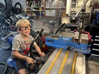
The next morning looking for a father son project, I let my 6 year old son machine the edges of the jaws square. He had a blast doing it! For the fun police, I made sure he had his safety glasses on and put both of my machine guards in place too.
IMG_6562.jpeg
any time he’s been in the garage with me he has been curious about the mill. I always keep the power locked out to it, so I think he was extra curious and excited to get to use it.
IMG_6564.jpeg
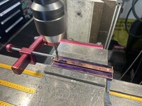
I then needed to drill and tap the blind holes for the ⅜” mounting bolts. First I measured the bolt width and zeroed the calipers
IMG_6567.jpeg
Then measured the width of the bolts. They are 4” apart on center. So I need to drill the mOunting holes 2” off of center
IMG_6568.jpeg
These holes need to be blind so I set the depth stop on the quill
IMG_6574.jpeg
And then let Stian turn the fine quill feed to drill the holes.
IMG_6602.jpeg
After the first two holes I showed him how to run the powered quill feed. He got a blast out of being able to pull a lever and have the machine do the work!
IMG_6625.jpeg
That’s about all his attention span would last for so we went for a bike ride. I thick he enjoyed working with the mill and seeing how we measure things etc. I don’t know how much of it he absorbed, but I feel exposing him to things like this will eventually get the wheels turning in his head on how to make things. I’ve been going through a nasty divorce and the next day found out I have a new temporary parenting plan that doesn’t give me any overnights, so I gotta pay my lawyer yet more money to fix it and fight for equal time with my son….at least what time I do get with him right now is quality time.
IMG_6610.jpeg
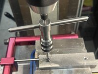
The next day I tapped the blind holes. I’m using these YG spiral bottom taps. They are cheap, yet cut extremely well. They are in my mind the best taps for the money around.
IMG_6621.jpeg
The tap guide in the quill not only provides downward force, it also keeps the tap square to the hole.
 
OP
G

Grant Gunderson

Well-known member
Joined
May 17, 2013
Messages
2,325
Location
Bellingham, WA
IMG_6620.jpeg
The spiral flutes in the tap pulls the chips up out of the blind hole so things cut smother and you are less likely to break a tap.
IMG_6626.jpeg
Next, I need to work on the ball detent for the jaws. After a bunch of research into ball detents I decided on using ¼” ball bearings.
IMG_6627.jpeg
First I need to drill a through hole that will allow a portion of the ball to pass through. Since the balls are .250 in diameter I decided to use a C size drill as it’s .242. If I decide I need more stick through I can always move up to a size D drill latter
IMG_6640.jpeg
I set the quill depth to allow it to through drill but not hit my dovetails. Using a work stop on the vise allowed me to quickly setup and drill all 4 holes efficiently
IMG_6633.jpeg
Step 1 done
IMG_6636.jpeg
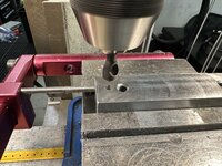
I now need to drill a ¼” blind counterbore hole for the ball to pass through. I’m using carbide drill bits for this.
IMG_6640.jpeg
I set the depth just shy of it passing through.
IMG_6647.jpeg
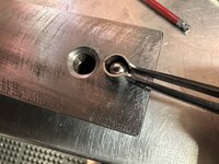
I then test fitted a ball bearing in each hole. Ball bearing tweezers make this a lot easier!
IMG_6644.jpeg
I then drilled the holes for a 5/16 set screw
IMG_6645.jpeg
Followed by a countersink
 
OP
G

Grant Gunderson

Well-known member
Joined
May 17, 2013
Messages
2,325
Location
Bellingham, WA
IMG_6648.jpeg
And then tapped.
IMG_6650.jpeg
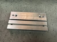
The machining on the jaw basses is now done.
IMG_6652.jpeg
I then blued them to keep them from rusting
IMG_6653.jpeg
The ¼” bearing gets dropped in to each hole followed by a spring. The 5/16 dog point set screw then sets the detent pressure on the balls.
IMG_6655.jpeg
They turned out pretty nice
IMG_6660.jpeg
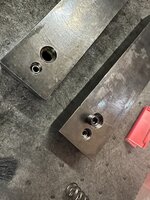
I then used a size C drill to make the correspond detent in each of the jaws. Having this joke exactly the same size as the ball portion sticking out gives the firmest detent. Going to a larger hike would make the detent softer.
IMG_6661.jpeg
I also broke the leading edges of each jaw to make it easier to slide pass the ball detents when inserting them.
IMG_6669.jpeg
They turned out great!
IMG_6671.jpeg
IMG_6674.jpeg
Here is all of my other interchangeable jaws with the dovetails now in them. Plus a set of blanks.
 

SilverJimmy

Well-known member
Joined
Apr 14, 2012
Messages
1,643
Location
Prescott/Flagstaff, AZ
I’m sure you said where you got those machine guards from at the time, but if you remember and how efficient are they at containing chips flying everywhere? Your shop is so compact I’m sure that is a very high concern of yours. I’m still getting my Ex-Cell-O mill set up and am worried about chip control. Thanks, and keep going, I learn stuff every time I visit your shop!
 
To avoid these ads, REGISTER NOW!
Top Bottom