To avoid these ads, REGISTER NOW!

300F electrical connection in Furnace Air Handler

gba2331

Well-known member
Joined
Sep 22, 2021
Messages
781
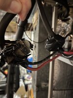
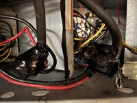
Our thermostat started behaving erratically so I got a replacement & installed it but it was providing heat when it should have been cooling. No worries, this t-stat probably has slightly different wiring, so I opened the air-handler to verify the connections there. That's when I saw this:
IMG_1521.jpeg

If you can't tell, the electrical tape on the right is "crispy". I could feel the heat coming off it, so I pulled out the infrared thermometer. The connection on the left was 85F while the right was 300F!

The unit was serviced in the spring and the tech noticed that the electrical tape had melted a bit then, so they rewrapped it but I guess we should have dug deeper. I'm not sure why a mechanical joint develops so much resistance, but we'll find out today when they come to examine it (since they should've caught this earlier, I figured I'd let them take a first crack at it....with "supervision" this time...).
 
To avoid these ads, REGISTER NOW!
OP
G

gba2331

Well-known member
Joined
Sep 22, 2021
Messages
781
This also seems like a sketchy way to connect (and then protect) the incoming power to the internal wiring, but I don't have any experience here...
 
OP
G

gba2331

Well-known member
Joined
Sep 22, 2021
Messages
781
Good question, I have no idea. There are no markings on any of the wires but the breaker is 110A and there are fuses inside the handler.

IMG_1533.jpeg
 
OP
G

gba2331

Well-known member
Joined
Sep 22, 2021
Messages
781
The crispy connection looks even worse on the back side, I guess the corrosion has spread inside the joint. IMG_1534.jpeg
 
OP
G

gba2331

Well-known member
Joined
Sep 22, 2021
Messages
781
Thanks for the advice, I'll talk with the tech about this. IMO, the wrapped free-floating bolt connections seem very sketchy....
 
OP
G

gba2331

Well-known member
Joined
Sep 22, 2021
Messages
781
No markings at all? That's odd.

I think I'd cut back that heavy gage wire a bit, replace the smaller ones with new and install with Polaris connectors, properly torqued
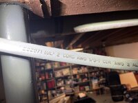
@mike93lx Sorry, I should have looked at the wire coming into the unit, it says "2 CDRS AWG 1/0-1 CDR AWG 2 AL", so I'm assuming that means 2 gauge Aluminum. Here's a picture:

IMG_1535.jpg
 
OP
G

gba2331

Well-known member
Joined
Sep 22, 2021
Messages
781
The tech came & basically said I need a new wiring clamp, but otherwise didn't give me much useful info or reassurance about why it happened, so I think I'll be doing this on my own using the recommendations provided here.
 

whateg01

Well-known member
Joined
Mar 13, 2006
Messages
11,459
Location
doo dah, kansas, usa
It happened because it wasn't tight and oxidation occurred. From there it snowballs, getting hot, causing further oxidation, etc. Depending on the damage to the wire itself the tech might find the wire itself needs to be replaced now.
 
OP
G

gba2331

Well-known member
Joined
Sep 22, 2021
Messages
781
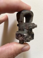
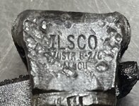
Here is the removed wire clamp - it seems hard to believe that a new clamp would corrode this much in 3 years? I haven't unwrapped the other one yet to see what it looks like.

IMG_1536.jpg
 

mike93lx

ALLIANCE MEMBER
Joined
Dec 9, 2013
Messages
37,864
Location
Richmond, VA
When you get it back together, I'd throw a clamp meter on both legs and make sure it's not out of balance also check voltage and follow the connections all the way back to the panel
 
OP
G

gba2331

Well-known member
Joined
Sep 22, 2021
Messages
781
It happened because it wasn't tight and oxidation occurred. From there it snowballs, getting hot, causing further oxidation, etc. Depending on the damage to the wire itself the tech might find the wire itself needs to be replaced now.

Thanks. This seems like something they should be covering since we detected the problem in May (but didn't diagnose properly)...but they're not. At this point, its simpler and more reliable to DIY.
 
OP
G

gba2331

Well-known member
Joined
Sep 22, 2021
Messages
781
When you get it back together, I'd throw a clamp meter on both legs and make sure it's not out of balance also check voltage and follow the connections all the way back to the panel
I did measure both legs before discovering the issue and both were drawing equally at 80A - which seems high to me, but I don't have any experience here.
 

BrandonV

Well-known member
Joined
Jun 9, 2023
Messages
4,030
Location
Arizona
Here is the removed wire clamp - it seems hard to believe that a new clamp would corrode this much in 3 years? I haven't unwrapped the other one yet to see what it looks like.

What is the model number of that clamp? Is it a Penn-Union?
 

joel63

Well-known member
Joined
Oct 9, 2012
Messages
1,912
Location
Central FL
Thanks for the advice, I'll talk with the tech about this. IMO, the wrapped free-floating bolt connections seem very sketchy....
No doubt about it, it definitely is.
Why in the hell do people do this kind of work????
 
To avoid these ads, REGISTER NOW!
OP
G

gba2331

Well-known member
Joined
Sep 22, 2021
Messages
781
I can't tell, I don't see any markings. My guess is that this is the original clamp from the previous (or previous-previous) system. The tech seemed to indicate that he would get a new replacement & didn't know about the Polaris type of plug, or even check the wire size before he left. Sigh...I thought this company was one of the better ones...
 

BrandonV

Well-known member
Joined
Jun 9, 2023
Messages
4,030
Location
Arizona
I can't tell, I don't see any markings. My guess is that this is the original clamp from the previous (or previous-previous) system.

I would suspect it is not rated for an Al conductor. The Al rated clamps use a special copper alloy (or are aluminum) and recommend the use of an oxide inhibiting compound to be applied with aluminum wiring.

Was the Al conductors new when the system was installed (replacing copper wire?).
 
Last edited:
OP
G

gba2331

Well-known member
Joined
Sep 22, 2021
Messages
781
To make things more interesting, the tech was able to pull out one of the four copper wires that runs to the internal fuses and another has scortch marks on it, maybe because the corroded wire clamp was making sporadic contact.
 

BrandonV

Well-known member
Joined
Jun 9, 2023
Messages
4,030
Location
Arizona
To make things more interesting, the tech was able to pull out one of the four copper wires that runs to the internal fuses and another has scortch marks on it, maybe because the corroded wire clamp was making sporadic contact.

The fact there are NO markings on the clamp is very odd. Sounds VERY old.
 

rmanrman

Well-known member
Joined
Nov 2, 2012
Messages
386
That connector is probably not rated for mixed aluminum and copper wires. Also whenever there is aluminum wiring there is a special paste that is applied to all conductors in the splice. Cut back to clean unchared wire and do new splices with approved connector for aluminum/copper wires. Also at 80Amps that must be an electric furnace. Your electrical bill will be very high.
 
OP
G

gba2331

Well-known member
Joined
Sep 22, 2021
Messages
781
Also at 80Amps that must be an electric furnace. Your electrical bill will be very high.
Its a heat pump but that may have been with the emergency heat kicking in, I dialed it up a good bit to get the system to engage.
Also whenever there is aluminum wiring there is a special paste that is applied to all conductors in the splice.
The tech mentioned Noalox and I bought some with the Polaris connectors, makes sense. I can't tell if there was any applied to the conductor.
 

mm08822

Well-known member
Joined
Jan 13, 2012
Messages
6,048
Location
NJ
@mike93lx Sorry, I should have looked at the wire coming into the unit, it says "2 CDRS AWG 1/0-1 CDR AWG 2 AL", so I'm assuming that means 2 gauge Aluminum. Here's a picture:

IMG_1535.jpg
That is 1/0, 1/0, and #2 Aluminum conductors.

What is the ambient temperature where the splices are and fuse block?
 

mm08822

Well-known member
Joined
Jan 13, 2012
Messages
6,048
Location
NJ
Here is the removed wire clamp - it seems hard to believe that a new clamp would corrode this much in 3 years? I haven't unwrapped the other one yet to see what it looks like.

IMG_1536.jpg
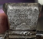
Looks overheated for sure. Clean up the area where the index finger is and take a pic of that printing so it is legible.
 
OP
G

gba2331

Well-known member
Joined
Sep 22, 2021
Messages
781
What is the ambient temperature where the splices are and fuse block?
This is inside the air handler for the HVAC unit (4 ton residential), so room temperature basically.

That is 1/0, 1/0, and #2 Aluminum conductors.
So does this mean that the #2 conductor is the unshielded aluminum in this pic? I'm just surprised that it isn't the same amperage as the other 2 wires.

IMG_1539.jpg
 

mm08822

Well-known member
Joined
Jan 13, 2012
Messages
6,048
Location
NJ
This is inside the air handler for the HVAC unit (4 ton residential), so room temperature basically.


So does this mean that the #2 conductor is the unshielded aluminum in this pic? I'm just surprised that it isn't the same amperage as the other 2 wires.

IMG_1539.jpg
Yes, the #2 is the manually wound strands. That's a typical cable construction.
 
OP
G

gba2331

Well-known member
Joined
Sep 22, 2021
Messages
781
I don't suppose there is a way to cut 1/0 AL wire with anything other than a $100-200 cable cutter?
 

mm08822

Well-known member
Joined
Jan 13, 2012
Messages
6,048
Location
NJ
It probably was not tight enough when assembled. If so, the entire mass becomes a heat generator. They can get cherry red if bad enough.

Upon repair, I would not splice 3 conductors together. Instead splice onto the end of the 1/0 and into the center of the other conductor used to feed the 2 poles on the fuse block.....it's one less splice and the amount of material to compress in the split bolt connect is less.
 
To avoid these ads, REGISTER NOW!
Top Bottom