To avoid these ads, REGISTER NOW!

Above 1200 Sq/FT Eastern Washington Workshop

Wokspaces above 1200 squarefeet.

GeddyT

Well-known member
Joined
Jun 17, 2015
Messages
1,243
Location
Bellingham, WA
Ha! I don't have 133 tools ;) The Tree tool rack has 54 tools on it. I started numbering at 131 for additional tools to help keep things straight.

I will openly admit I'd much prefer to add inexpensive tool holders than break them down. I'll probably order another batch of the TPAC ER16 and ER20 tool holders.

Maritool doesn't do the helical version of those chamfer mills in 82 degree. I'm not following the chamfer width piece yet. I'll do some reading. That's definitely the way to do it! Thank you! I use the peck drill cycle for the 82 degree chamfers currently. It was fine in aluminum. The low surface speed for steel is what kicked my ****. Interpolating the chamfer will work much better once I have a recipe.

A quick search brought this up:

So say you want to countersink an M6 flat head socket screw (the most common fastener that I use). I just google the dimension of that screw, and the head has somewhere between 12 and 13.5 mm head diameter. I don't model chamfers, just the hole. So an M6 through hole is 6.4 mm. I select the hole face contour for chamfering and choose 3.5 mm as the chamfer width. 3.5 + 3.5 + 6.4 = 13.4 mm, which is right at the top of the range for an M6 screw, so it should sit flush with the face of the part when screwed in.

Weirdly, the instructions always talk about choosing the bottom of the chamfer. I never do that. I always choose the surface contours I want to chamfer, keep the defaults in the heights tab, and just choose a chamfer width and small tip offset (because the chamfer mill doesn't come to a fine point). It works every time.
 
To avoid these ads, REGISTER NOW!
OP
S

slodat

ALLIANCE MEMBER
Joined
Feb 6, 2010
Messages
3,682
Location
Central-ish, WA
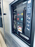
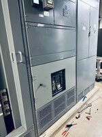
Been a really busy… year! Received an installed photo from the client on some parts I shipped last week. Here’s a before and after:
IMG_3482.jpeg

The contractor used an enclosure from a different manufacturer. This resulted in the front covers not working out. I came up with a design based on a few measurements from them and it worked out well. Really satisfying to see the installed photo.

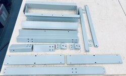
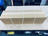
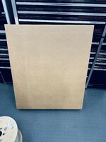
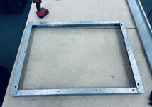
I’ve been putting in some long days getting these orders filled. I am so happy with the packaging and shipping process and end result. This is a sheet metal and hardware order I shipped a couple days ago:

IMG_3473.jpeg

IMG_3478.jpeg

IMG_3479.jpeg

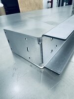
The engineering team doesn’t always design parts I can make with my machines and tooling. This bend is a fine example:

IMG_3470.jpeg

I reluctantly slotted the bend, and bent on the fixture table. The bracket will do the job and we move on to the next.

Next up was my first hinged door. I had to do the design, including a different hinge, make it all, and then I installed on-site at a federal facility in DC. The first one took a lot of time. Some important lessons learned, and it was a success.
One challenge was the breaker is set back from the front plane of the gear enough that it needed to be managed. This is what I came up with.

IMG_3489.jpeg

The four inner sides keep fingers from gaining access into the gear. This is the end result of that feature:

IMG_3515.jpeg

IMG_3516.jpeg

And the installed photo of the door.

IMG_3512.jpeg

I’m well aware the paint doesn’t match. It wasn’t for a lack of trying. @cycle61 had sent a sample of the color. My paint shop used their doodad, and it doesn’t match. As cringe worthy as the paint is, the rest worked out well. I could point out all the things I’ll improve on the next one, but it doesn’t matter on this one.
 
OP
S

slodat

ALLIANCE MEMBER
Joined
Feb 6, 2010
Messages
3,682
Location
Central-ish, WA
I’m glad you’re enjoying the packaging stuff. I’m blown away at how satisfying it is. Even more so, having the right supplies and packaging equipment make it so much easier. I flew with this box yesterday. 48 x 36 x 6”. Arrived unscathed, in checked baggage.

I think the other aspect is, when it’s getting boxed up, it’s done!
 

Attachments

  • IMG_3490.jpeg
    IMG_3490.jpeg
    726.7 KB · Views: 38

RickP

Well-known member
Joined
Jan 15, 2013
Messages
1,554
Location
Annapolis, MD
Really nice work!

What's amazing to me that the federal project budget includes flying you to DC to install the door... But having worked in DC on federal projects before, I am definitely not surprised. The finished installation looks great.
 
OP
S

slodat

ALLIANCE MEMBER
Joined
Feb 6, 2010
Messages
3,682
Location
Central-ish, WA
Thank you! I have to remind myself to not only see the flaws.

This was a punchlist item that I took care of on a trip for something else. I’m pretty sure my customer didn’t make any money on me installing the door. It was to close that project out for his client. My primary reason for going to DC was to take measurements for another project in the area. All these projects have a line item for a trip to get measurements during an outage.
 
Last edited:
OP
S

slodat

ALLIANCE MEMBER
Joined
Feb 6, 2010
Messages
3,682
Location
Central-ish, WA
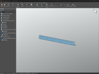
Working on reverse engineering a piece of equipment to use as a reference for making parts, modifications, etc. There's a lot of this out there, and plenty of work coming from this equipment. First order of business is to model the base frame.

IMG_3828.jpeg

Pretty simple parts. The hole placement is critical to these parts working correctly. It took three different scans to get everything.
IMG_3832.jpeg

In this scan we can see the black section, there's no data there.

View attachment 1970418

This is the first two scans aligned.

View attachment 1970419

All three scans aligned. Now we have the whole part, from all sides.

View attachment 1970420


In QuickSurface. I'm getting a little faster in QS. The modeled part in QS:

1697041031821.png


The heatmap comparison:
1697041139984.png

The model was brought into Fusion, into the assembly. Then, I noticed this:
1697041252096.png

The right-hand vertical component (corner post) upper hole doesn't line up with the base frame. Hmm.. I didn't scan the holes in the corner post. I measured spacing and did a pattern across the part. Whelp...

IMG_3831.jpeg


1697041416729.png

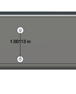
Turns out the top and bottom three holes on the corner post are ~1" spacing, and the rest are ~1.25" spacing.

1697041516403.png

The scanner is more than earning its keep. Cool stuff.
 
OP
S

slodat

ALLIANCE MEMBER
Joined
Feb 6, 2010
Messages
3,682
Location
Central-ish, WA
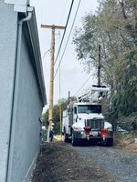
This week started off with no power in the shop the whole day Monday. Neighbor put a shop in, and the PUD wanted to replace the pole and the transformer for his new service. It's really fascinating watching line crews do their thing.

IMG_3872.jpeg

There's only one transformer though. If and when I bring in a three phase service, I'll be paying a pretty penny for it.

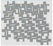
I'm doing a bigger run of parts for a client this week. This particular part I'm making forty of them. I turned on Fusion 360's Nesting and Fabrication Extension 14 day free trial to see how the nesting would work with this part. It did a great job of getting the most out of the material.

1697762402439.png

I had cut a test part out of the corner of the sheet, and I didn't want to be wrong, so there's some material left at the beginning of the sheet. It will get used on the next part. Nothing lost there.

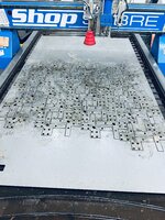
This is the biggest single cutting file I've run on the plasma. 40 parts, 440 holes, 480 pierces in 11ga (0.120") HRPO (hot rolled pickled and oiled) mild steel. It took about 90 minutes to run these parts on the plasma. This definitely shines a light on the value of a fiber laser.. One thing at a time ;)

IMG_3895.jpeg

It looks like I have 40 good parts to debur, sand, bend, and paint. These are a gusset for a piece of electrical equipment.
 

Finallygotit

ALLIANCE MEMBER
Joined
Jul 6, 2013
Messages
4,090
Location
Tucson, AZ
We had a microburst hit us back in August which blew down about 16 power poles on two roads. Like you said, it was amazing watching those professionals do their work. One road got all steel poles while the other got wood replacements. I guess the steel poles was due to the extra power that a local Bayer greenhouse needs to run their place.

:beer:
 
OP
S

slodat

ALLIANCE MEMBER
Joined
Feb 6, 2010
Messages
3,682
Location
Central-ish, WA
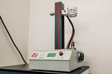
Pretty exciting additions to the shop are on the way. Haas had a really good special going on their tool pre-setter and shrink fit machine. Ended up being 30% off, and 20 tool holders thrown in to sweeten the deal.

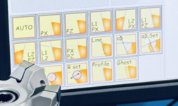
The pre-setter is pretty slick. It measures tool diameter and length. The diameter is particularly interesting for me. I don't really have a way to check things on diameters due to the nature of tooling and the limited amount of measuring tools I have. In addition to diameter and length it can also do things like tell you when insert in a shell mill is the lowest, etc. This integrates really well with their latest control. Not a thing for me today, but I like the possibilities. Should be a big timesaver, as well as improve the quality of the parts I'm making along the way.

1697776018280.png

The shrink fit machine has an induction heater to heat up a shrink fit tool holder. It expands, the tool is dropped in, and then the machine uses an air blast to cool the holder off. The clamping force a lot higher than collet holders, the runout is very low, and they fit in small pockets because of the small nose diameter.

1697775996926.png

I went with the shrink fit machine because of their promo. I’m excited to get this stuff in service.
 
Last edited:

loganb

ALLIANCE MEMBER
Joined
Dec 29, 2011
Messages
5,579
Location
Omaha, NE
I think you're going to like the shrink fit! Made a similar move on tooling on some CNC routers in a plant I used to work in, went to the shrink fit tooling on HSK spindles for wood routers running a lot of MDF and 4/4 lumber. Tooling life went up, cut finish was better as less runout, reduction in tooling setup errors....overall a big win!
 
OP
S

slodat

ALLIANCE MEMBER
Joined
Feb 6, 2010
Messages
3,682
Location
Central-ish, WA
@loganb that’s what my thinking is as well. My parts have a comfortable tolerances in a lot of cases. I’m always trying to make the best parts I can with what I have and what I know. This sort of support equipment can make a significant impact on quality and time. I’ve always known using inexpensive import collet tool holders is less than ideal and will need to be addressed at some point. I have some fresh new end mills that will go in the shrink fit holders for finishing passes. I’m thinking the new chamfer mills @GeddyT recommended from Maritool make sense in a shrink fit as well.
Thanks for following along and contributing to the conversation!!
 

GeddyT

Well-known member
Joined
Jun 17, 2015
Messages
1,243
Location
Bellingham, WA
Is there a drool emoji?...

I've been so busy at work (and coming home and collapsing after) that I haven't even really checked the forum in a while let alone contributed, but this is quite the thing to return to! The projects I've been working on lately (sign making) have required ever smaller milling and engraving tools, and I'd love to be able to shrink them into holders. I looked into it a while back, and my jaw hit the floor at the price of even the Maritool shrink-fitter, which I believe is the lowest cost on the market. At almost what I paid for the mill itself, I couldn't justify it.

Oh, you bet I was on the forums and YouTube immediately after, looking at redneck shop-built heat shrink solutions on the cheap using Chinese induction heaters! There are, of course, a lot of opinions and options on that route out there, and none of them would be as automatic, repeatable, and reliable as a dedicated machine like that Haas, and they wouldn't have the built in tool-setting and insert tracking (which is pretty incredible).

BUT... cheeeeeeeeap. I might eventually get around to it, then you can laugh at me! In a production environment like yours, you don't have time to dink around like that. Buy the professional tools and move on to making money.
 
OP
S

slodat

ALLIANCE MEMBER
Joined
Feb 6, 2010
Messages
3,682
Location
Central-ish, WA
I had a hell of a time with the 40 parts I previously posted about. I’m not sure how it hasn’t come up before.. I had a lot of low speed dross on the parts that took a ton of work to remove.

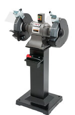
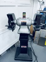
I’ve had a Jet JBG-8 8” bench grinder since 2009 or so. I have always used it with a deburring wheel and a wire wheel. The grinder has always felt underpowered and easy to stall out when leaning into the wire wheel. I’ve looked at upgrades a few times this year. Always after a big deburring session on plasma cut parts. Turns out Jet makes two lines of bench grinders. Mine is the lighter duty offering. Generally speaking, I want higher quality tools than Jet offers. With that said, I have no complaints about the lighter duty grinder I have. I’ve read good things about the more industrial offerings.
I spent way too much time today looking at bench grinders, and wire wheels. In the end I couldn’t justify $6k or more on a new Baldor. Home Depot’s 10% veteran’s discount put the 12” Jet Industrial bench grinder and stand within the budget. Looks like about two weeks to get here.

IMG_3905.jpeg

The other half of the equation was learning about wire wheels and sourcing what I think/hope I need. Weiler looks to be a reputable USA maker. Ordered a double row knotted wheel for one side and a 2” wide crimped for the other.

Of course, I also addressed the cause of the excessive low speed dross. I had been using the 10ga profile on the plasma. I made a 11ga profile that’s about 15ipm faster. Did a few test cuts and the dross is right back to minimal and about as good as I’ve gotten it. Excited to get the more powerful grinder in service. Should speed deburring considerably.

The 40 parts after all the metal prep:
IMG_3899.jpeg

The press brake makes quick work of the bending.

IMG_3900.jpeg
 
Last edited:
To avoid these ads, REGISTER NOW!
OP
S

slodat

ALLIANCE MEMBER
Joined
Feb 6, 2010
Messages
3,682
Location
Central-ish, WA
Thanks for the encouragement, guys! Those parts turned out okay after a lot of hand work to clean up the dross.

Becuase of that, I spent did some much needed maintenance on the plasma table. The torch crashed into the side of the water table a while back during a drilling operation. Shop Sabre replaced the torch, thankfully. It's not something that should be able to happen. It bent the torch pretty good. I was able to straighten it with a sleeve to hold me over.

IMG_3912.jpeg

Once that was done I had to realign the torch to the drill unit.

IMG_3914.jpeg

One adjustment and I was back in business. Lastly, I adjusted the 11ga HRPO profile in the control. This is what I'm seeing now for dross:

IMG_3918.jpeg

A quick pass, with very light pressure, over the wire brush and it falls right off. Some parts are a little less than pictured. I'm happy with it.
 
OP
S

slodat

ALLIANCE MEMBER
Joined
Feb 6, 2010
Messages
3,682
Location
Central-ish, WA
If you haven't already purchased, I suggest getting a belt grinder instead of another bigger bench grinder.
Justin - I have a Burr King 2x60 belt grinder that I use daily. When it comes to removing the dross, I want the process to leave as little witness mark as possible. The belt grinder hasn't proven the best tool of what I have on hand for this. When I need to touch up the edge of a part, the belt grinder is my go to. I have tried pretty much every type of tool I have - belt grinder, band files, angle grinder with various abrasives, etc. I'm most satisfied with the wire wheel on the bench grinder. On parts too large for the bench grinder, I use a knotted wire wheel in a cordless 5" grinder.

The reason I went with a bigger and more powerful bench grinder is because the Jet I have has always had trouble with stalling when I lean into it much at all. My thought is I'll never be mad about having a bigger pedestal grinder. When I really dug into wire wheels ("brushes"), I learned a lot. I think I have some good stuff on the way. I found some deals on 12" stuff on ebay so I bought a small assortment to try out.

Please share your thoughts and experiences! I have wanted the Ameribrade belt grinder setup for general fabrication work for a while, but didn't think it would be best bet for removing dross and deburring.

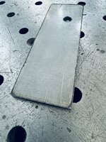
This is a part I just ran:

Top side:
IMG_3920.jpeg

Bottom side:
IMG_3921.jpeg

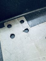
Minimal dross in my opinion. A bit more around the holes.
IMG_3922.jpeg

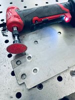
The 36 grit 2" roloc in the Milwaukee die grinder makes quick work of cleaning up the holes.
IMG_3923.jpeg

This has been working. I am VERY open to suggestions!

Material is 11ga HRPO, Hypertherm 85, 45a Fine Cut consumables.
 
Last edited:

rvieceli

Well-known member
Joined
Nov 3, 2013
Messages
779
Location
Illinois
@slodat have you thought about a wide belt sander to remove that stuff? A smaller model would probably work for your parts.

Not the cheapest piece of equipment but they regularly come up on sale sites and at auction.

Ron
 
OP
S

slodat

ALLIANCE MEMBER
Joined
Feb 6, 2010
Messages
3,682
Location
Central-ish, WA
@slodat have you thought about a wide belt sander to remove that stuff? A smaller model would probably work for your parts.

Not the cheapest piece of equipment but they regularly come up on sale sites and at auction.

Ron
Ron - you are right! A deburring machine/wide belt sander is the right tool for the job. They are a lot of money (new), and the woodworking models don't do well with metals. Different machines internally. More importantly, they need a LOT of power that I don't currently have.

The 800a 240v 3 phase service is looking like $60k. It's going to be a while before I will be up for that. It's a necessity at some point. Add the price of the deburring machine and it's a $100k+ investment.

For now, I use more manual methods. Thankfully, I don't do large production runs of parts off the plasma. The order I'm working this week is the largest number of parts I've done in one order, but that's not the norm.

edit: I stand corrected! Thanks for kicking me in the *** to take a look at these machines.. Looks like a 10hp single phase machine is in the $20k price range. Not chump change by and measure, but a lot less than I thought and single phase is an option.
 
Last edited:
OP
S

slodat

ALLIANCE MEMBER
Joined
Feb 6, 2010
Messages
3,682
Location
Central-ish, WA
@slodat wouldn't your tumbler with an aggressive media handle the dross? Just asking...
I have used the tumbler for smaller part dross removal and deburring. It takes a while. The dross was really bad on these parts and I didn't think tumbling would work. Generally speaking the tumbler takes longer than I have available. I'm always on tight timelines on the steel parts.
 
OP
S

slodat

ALLIANCE MEMBER
Joined
Feb 6, 2010
Messages
3,682
Location
Central-ish, WA
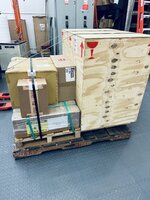
This arrived.

IMG_3958.jpeg

The cabinet is pretty disappointing especially considering what they charge for it. It was part of the package, so I didn’t buy it separately. It did go together just fine. Just felt rather flimsy.

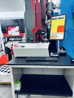
The presetter:
IMG_3968.jpeg

It’s tucked in behind the VMC. It will get a cover to keep it from getting dusty or dirty when not in use. The presetter itself is a really nice machine. It's really cool to see the difference in X and Z between the flutes of a cutter.

IMG_3967.jpeg
 

gearhead1960

ALLIANCE MEMBER
Joined
Mar 21, 2019
Messages
1,862
Location
Manassas, VA, a small blot in history
Austin- the software UI design is definitely a bit dated. It does seem to work really well. Especially considering it’s running on windows 10.
....if it ain't broke, don't fix it. I think to often companies try to make their products better when they don't need to. In this case perhaps Haas decided to stick with tried and true... :beer:
 
OP
S

slodat

ALLIANCE MEMBER
Joined
Feb 6, 2010
Messages
3,682
Location
Central-ish, WA
....if it ain't broke, don't fix it. I think to often companies try to make their products better when they don't need to. In this case perhaps Haas decided to stick with tried and true... :beer:
The presetter is made by an Italian company, M. Conti. The crate said made in Italy, and I found this online:

IMG_3969.jpeg

I did find another US distributor of their presetters.

I do agree with both you.. the UI design is dated, and if it works don’t break it.

Now if Haas will ship the shrink fit holders this week I’ll be good to go on that front as well.
 
OP
S

slodat

ALLIANCE MEMBER
Joined
Feb 6, 2010
Messages
3,682
Location
Central-ish, WA
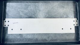
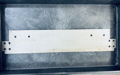
I spent some shop time today working up a shelf for the shrink fit machine.

1698631199269.png

Made it out of 11ga because I had some on the plasma. It would be plenty strong..

IMG_3970.jpeg

It's cutting really nicely since the maintenance last week. IMG_3972.jpeg

Parts turned out great, ready to go.. Or.. not. The cabinet the presetter is on is too flimsy to attach the shelf and bracket to. I could have drilled a hole higher up, but I know better. So, I made some nice looking scrap.. Settled on this:

IMG_3973.jpeg

This is the cleaner side of the machine room. Not much in the way of chips find their way over here. This will work just fine.
 
OP
S

slodat

ALLIANCE MEMBER
Joined
Feb 6, 2010
Messages
3,682
Location
Central-ish, WA
IMG_2419.jpeg

You should be able to make this part I would think. Full width punch and a small piece of lower die… but you’d probably have to cut one if you don’t have a lower segmented die.
I have segmented upper and lower dies. There are a few challenges with this bend:
  • The C channel must be formed first, or the two end bends will crash into the punch/die/ram/bed. In the photo you can see that the leg is much longer than the channel depth. I looked at moving the punch mounts to create clearance, but the leg was still too long for that to work.
  • Given the C channel must be formed first, then the ends have to be bent last. The end of the leg can't go into the brake because the channel is taller than the die, thus hitting the bed.
  • The part can't go into the brake the hard way ("backwards") because it will crash into the upper structure of the brake/ram.
If I had a tall die or die riser I could have bent the part on the brake. There are several ways I could have changed the design to make the part manufacturable with the tooling I have. In the end, it wasn't worth it. The customer was happy with the way the part was made.

With all that said, please don't think I'm being argumentative or defensive. You have helped me more than a couple times see things from a different perspective that has helped me get a part made. I REALLY appreciate that, and your curious eye. Thank you! I actually had considered another part you suggested I hang off the end of the dies when I made this part. In the end, I didn't see a way to get it made with what I have.
 
OP
S

slodat

ALLIANCE MEMBER
Joined
Feb 6, 2010
Messages
3,682
Location
Central-ish, WA
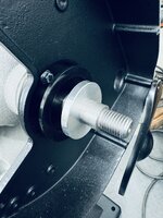
The big Jet grinder arrived. I have to say I am quite happy with it and their stand. I had to make some spacers in order to mount the wire wheels. Their mounting flanges vary in width and are smaller than the brush width. The Pacemaker is such a dream to run for parts like this. They turned out nice.

IMG_4019.jpeg

IMG_4027.jpeg

IMG_4028.jpeg

IMG_4029.jpeg

This is a really smooth running grinder with plenty of power. I leaned into it hard with some dross that the 8" grinder would stall out on. It still takes some effort on the grinder's part, but it took the dross off without issue. That's what I was wanting.

IMG_4030.jpeg

Time will tell if I leave the tool rests on. I've never liked them with wire wheels. Now that I'm writing that, I'll take them off. Too easy to get a part between the rest and the wheel. Overall first impressions are really good. I'm happy to have it in the shop.

The Haas shrink fit tool holders arrived as well. From what I've read online most folks agree that they appear to be made by YG1. Good stuff.

IMG_4006.jpeg

Haas doesn't offer 1/8 or 1/4". I'm sure I'll order one of each at some point.

IMG_4007.jpeg

All loaded up.
 
To avoid these ads, REGISTER NOW!
Top Bottom