To avoid these ads, REGISTER NOW!

Rebuilding a monarch 10ee lathe

To avoid these ads, REGISTER NOW!

gba2331

Well-known member
Joined
Sep 22, 2021
Messages
776
My schoolteacher friend published a book for high school kids on the stock market. He doesn’t earn much but it sells a few copies a year and the printed book looks nice.
 
OP
G

Grant Gunderson

Well-known member
Joined
May 17, 2013
Messages
2,323
Location
Bellingham, WA
I received the proper bearings for the Screw Shaft Assembly.
IMG_8805.jpeg
The left side is SKF 6203 2RSNRJEM. the right side is SKF 6205 2RSNRJEM. these come with retaining rings on them.
IMG_8865.jpeg
Small problem. The retaining rings SKF uses are way to large of OD. I tried some standard external retaining rings, but they are still way too wide. I ended up having to order some low-clearance external retaining rings. These are the perfect size. It is unfortunate they dont make these more fully envelop the bearings diameter, but this the only solution I could find. Here are the links to the correct sizes at McMAster: 9968K27 and 9968K28
IMG_8867.jpeg
I put some retaining compound on them and they snapped into place.
IMG_8886.jpeg
I then replaced them on the shaft.
IMG_8887.jpeg
IMG_8806.jpeg
The tab on the new locking washer was slightly too thick so I filed it down to size.

I could then snug down the bearing retaining nut and lock it into place with the conical retaining washer. Since these bearings have the locating rings on them now, the shaft doesn't bind up when the nut is torqued down. The tumbler shaft is finished! All thats left on the gear box is assembling the front of the round dial.
 
OP
G

Grant Gunderson

Well-known member
Joined
May 17, 2013
Messages
2,323
Location
Bellingham, WA
With the screw shaft back in and reinstalling the tumbler plunger assembly, I can now start on the front of the round dial. Finally!
IMG_8640.jpeg
The index shifter shaft goes in next.
IMG_8641.jpeg
It just slides in and I aligned the witness marks I made on it and the Tumbler plunger shaft during tear down.
IMG_8643.jpeg
The rest of the front plate internals go in next.
IMG_8644.jpeg
The gets cam placed back on the index selector shaft, with the ground washer placed on the tumbler plunger shaft above it with the bevel side facing out. When you operate the Tumbler lock lever, the cam then drives the Tumbler plunger shaft at the top of the photo in / out thus activating the Tumbler locking mechanism.
IMG_8645.jpeg
One of the stop pins (aka ¼-20 alignment pins) was bent, so I replaced it with a new one on the left.
IMG_8646.jpeg
I used a bit of blue lock tight on the pins to help prevent them from backing out.
IMG_8648.jpeg
The back plate slides on and gets retained by 4 SHCS.
IMG_8649.jpeg
The small gear slides onto the Tumbler plunger shaft
IMG_8651.jpeg
The large index gear then slides onto the Index shifter shaft. Note the factory witness mark dimples get aligned.
IMG_8653.jpeg
I found a Bronze round dial to replace the pot metal that came on my machine. Here is where I learned something very interesting. The hole for the thread / feed shifter index pin is in different locations!
 
OP
G

Grant Gunderson

Well-known member
Joined
May 17, 2013
Messages
2,323
Location
Bellingham, WA
IMG_8923.jpeg
The index pin on my back plate looks like it had been modified. It has a recess for both an upper and lower pin location. There is a larger pin that was in there that then got drilled off center to scope the pin. Regardless it's still in the wrong spot for the Bronze dial. My best guess is these got drilled by hand after the dials were all installed.
IMG_8919.jpeg
Ok, let's see if I can figure out what's going on here. Notice the index arrow on the knob that supposed to point to if you have Threads or Feeds selected is on the wrong side! It's on the side with the notices in the index plate. Being this was a July 1944 machine that ended up at Westinghouse / Hanford, WA it's not too suprising that a detail like this got overlooked
IMG_8922.jpeg
I could switch the plate around to the proper side, but its a bit tricky as its pinned in place with the pin going into the key.
IMG_8921.jpeg
Ok, so this got me thinking, maybe I screwed something up. So I pulled the round dial back plate back off to check the function of everything. Everything is working properly, and I aligned the shaft with the drilled dimple mark. I'm guessing this is from the locating pin that indexes it into either Feeds or Threads being hand drilled.
IMG_8918.jpeg
Once again checking the alignment position of the knob and it's index's with the plates show the Bronze one has the hole at least drilled to being in to close to the correct location but not perfect. (close enough if I pull the shaft and rotate it by a gear tooth it wont be any closer. However the pin hole location on the original pot metal plate only locks the knob into one location, not both as it's supposed to.

So I have a back plate with tow pin holes in it, but neither are correct and a knob that clearly has the index installed aproximately 180 to its proper location. In order to properly fix it I need to plug the holes for the index pin in the original. I think I will do this by drilling them out, remains them and pressing larger pins in. Then I will find the correct location for the proper pin location and bore a new hole and press a new pin in. Finally I'll need to fix the knobs index.


So once again two steps forward one step back.
 

Attachments

  • IMG_8918.jpeg
    IMG_8918.jpeg
    667.1 KB · Views: 3
  • IMG_8655.jpeg
    IMG_8655.jpeg
    593.9 KB · Views: 4
OP
G

Grant Gunderson

Well-known member
Joined
May 17, 2013
Messages
2,323
Location
Bellingham, WA
Ok finally back to work on the gear box after being way to busy with life
IMG_9171.jpeg
The dials for the gear box need a good polishing. I start with a daily hard wheel and brown compound.
IMG_9172.jpeg
I then move to the next softer wheel and red compound.
IMG_9173.jpeg
I clean them between each compound with alcohol. I then finish with an even softer wheel and the blue compound. I'm going to repaint these to make them stand out. The pot metal one that was originally on the lathe is going into the box with the rest of the parts I want to get chromed when finances allow.
IMG_9174.jpeg
The bronze dial then gets cleaned with some wax and grease remover.
IMG_9175.jpeg
I then coat it with black enamel. The rustoleum stuff takes for ever to fully cure to a full hardness. So after a few hours, I simply rub the paint off of the high spots.
IMG_9178.jpeg
Here is the end result. I'll do the same to the pot metal version once it's chromed. Moving on to fixing the stop for the Threads / Feeds knob.
IMG_9206.jpeg
After much time spent with layout ink and trying to decide upon the best corse of action, I decided to leave the lower incorrect hole alone and just remove the pin they had in it. I then drilled out and then reamed the upper pin hole that was at least close to the correct spot to press fit in a 5/16 X 1" down pin.
IMG_9194.jpeg
At some point I should invest in yet another Huot drawer index to fit my reamers. But for now they live in a Lista drawer by size. To make it easier to identify if a reamer is on size, 1 thou under or over, I had some glue filled heat shrink to them. Green is for on size, black is under and red is over.
IMG_9180.jpeg
I then need to remove the index from the knob. It's held in place by a pin that is pressed into the machine key inside of it. A ⅛ pin punch makes quick work of that.
IMG_9181.jpeg
Here you can see the key with the pin attached to it driven out.
 
OP
G

Grant Gunderson

Well-known member
Joined
May 17, 2013
Messages
2,323
Location
Bellingham, WA
IMG_9183.jpeg
I then use a brass drift to drive out the index. Should have done this on the arbor press, but this was quick.
IMG_9184.jpeg
Here is the index plate for the knob. One notch is close to the correct spot. The other is way off.
IMG_9209.jpeg
I started by brazing the notch that was in the incorrect location mostly full. My little benzomattic map/ oxygen torch is really inadequate for this. I need to invest in a proper brazing setup. Eitherway, it worked. I then use a 5/16 mill to enlarge the notch that was in the correct location.
IMG_9212.jpeg
I then used a jewelers file to demure the edges and round the lips a bit.
IMG_9207.jpeg
I then checked it's fit. Perfect.
IMG_9213.jpeg
and then applied some Dyekem to the pin and tapped the index on it to locate where it should reside.
IMG_9215.jpeg
I then scribed it to get a better idea of how to line the end mill up on it.
IMG_9216.jpeg
I then used the same dyekem on the pin to locate how the hole needs to get enlarged on the back of the bronze bezel.
IMG_9222.jpeg
Bronze bezel fits perfectly. I then test fitted the index, and its right on the money!
IMG_9223.jpeg
I used my calipers to transfer the location for the pin hole to the correct location on the knob. IT needs to be on the arrow to align properly.
 
OP
G

Grant Gunderson

Well-known member
Joined
May 17, 2013
Messages
2,323
Location
Bellingham, WA
IMG_9224.jpeg
I then spot drilled the knob and then drilled it and finally reamed it to be undersized for a ⅛ pin to press in.
IMG_9225.jpeg
I aligned the new pin holes and pressed the index back into the knob.
IMG_9226.jpeg
an alignment punch fine tunes the fit.
IMG_9228.jpeg
I then pressed the machine key with the ⅛ pin back in.
IMG_9230.jpeg
It now index's perfectly and the 5/16 pin is rock solid and the arrow actually aligns with what its induction now!
IMG_9233.jpeg
I can now put the cam and washer back in to the gear box.
IMG_9235.jpeg
The back plate for the round dial then gets secured using 4 SHCS.
IMG_9236.jpeg
The upper and lower gears get dropped into place and aligned with the factory witness marks with it rotated full CCW. This is important as it is what properly aligns the pointer.
IMG_9245.jpeg
The dial gets secured with 4 countersunk brass screws.
IMG_9242.jpeg
I used an 8-32 thread forming tap to clean out the holes in the larger gear to accept the indicator.
 
OP
G

Grant Gunderson

Well-known member
Joined
May 17, 2013
Messages
2,323
Location
Bellingham, WA
IMG_9261.jpeg
The indicator gets secured with 4 filter head screws 8-32 x 5/8

IMG_9262.jpegThe woodruff key then gets inserted into the shaft for the cam.
IMG_9263.jpeg
I still need to paint the locking lever, but we can test fit it now. It is retained by a ¼-20 dog point set screw, so I chased its threads.
IMG_9267.jpeg
and then secured it.
IMG_9268.jpeg
I then installed the center knob and reamed it with a #1 pin reamer.
IMG_9269.jpeg
I gave the new stainless taper pin a good coating of tea-gel. I want it to be easy to remove as I'll need to pull it latter to paint the locking lever and send the jobs for chrome.
IMG_9270.jpeg
The Feed / Threads knob slides on to its shaft and a spring gets inserted .
IMG_9275.jpeg
It then gets secured by its center screw. This will get chromed latter. I then installed the ABC selector knob and pined it into place temporarily.
IMG_9276.jpeg
I then used a drift to drive in the plug on the right rear of the gear box.
IMG_9277.jpeg
It sits flush with the casting.
 
OP
G

Grant Gunderson

Well-known member
Joined
May 17, 2013
Messages
2,323
Location
Bellingham, WA
The Feed Rod Plate gets assembled next.
IMG_9281.jpeg
I start by chasing the threads for the pins thats retainer the bearing separator. There is two of them.
IMG_9282.jpeg
The replacement bearings are a WC87503
IMG_9283.jpeg
New bearing is on the right. These are shielded on both sides.
IMG_9284.jpeg
I used a Park Tool bearing drift in the arbor press to press the first bearing in.
IMG_9286.jpeg
It needs to sit flush with the casting.
IMG_9287.jpeg
Here you can see how the bearing spacer was drilled to accept the two locking pins. Note its off center. The thinner side faces the bearing we just pressed in.
IMG_9289.jpeg
I lined it up with both of the pin holes and used the bearing drift plus an extension to press it in.
IMG_9290.jpeg
I then secured it with both of the threads pins.
IMG_9292.jpeg
I finally pressed the second bearing in.
IMG_9293.jpeg
IT will sit bellow the surface of the casting.
 
OP
G

Grant Gunderson

Well-known member
Joined
May 17, 2013
Messages
2,323
Location
Bellingham, WA
Next I need to install the oil seal for the shaft.
IMG_9295.jpeg
The original Seal on the right is a bit of an odd ball. The shaft size is standard, but the bore size is larger than standard.
The metal SKF in the middle wouldn't work.
IMG_9297.jpeg
However the double seal version I ordered did fit as it uses a rubber outer seal too instead of the SKF metal side
IMG_9298.jpeg
It was a very tight press fit in with the arbor press.
IMG_9299.jpeg
The large machine bushing then goes over the outer bearing.
IMG_9300.jpeg
It sits flush with the casting.
IMG_9301.jpeg
I lubed the shaft and the slid it in.
IMG_9302.jpeg
The woodruff key then gets tapped in.
IMG_9303.jpeg
and the gear then gets pressed on. The side with the shoulder on it faces into the bracket for the proper offset.
IMG_9304.jpeg
I used a thread forming tap to chase the hole.
IMG_9305.jpeg
and finally secured the gear in place with a set screw.
 
OP
G

Grant Gunderson

Well-known member
Joined
May 17, 2013
Messages
2,323
Location
Bellingham, WA
IMG_9306.jpeg
I then needed to make a gasket for the feed rod plate.
IMG_9313.jpeg
Its now ready to install.
IMG_9308.jpeg
Twisting its shaft helped to align the gears while slinging it into place.
IMG_9309.jpeg
I had to cut a 3." bolt down to fit one of the hole locations.
IMG_9310.jpeg
I picked up this deburring tool for the hand drill to chamfer the ends of rods.
IMG_9311.jpeg
IT worked great to clean up the cut threads.
IMG_9312.jpeg
I then appleid some tea-gel to all of the bolts.
IMG_9314.jpeg
all thats left for the gear box is the oil sight glass.
IMG_9316.jpeg
The cork gasket I made goes in to the bezel first,
IMG_9317.jpeg
followed by the glass.
 
OP
G

Grant Gunderson

Well-known member
Joined
May 17, 2013
Messages
2,323
Location
Bellingham, WA
IMG_9318.jpeg
I marked the centerline for the back plate.
IMG_9319.jpeg
It gets an o-ring on the back
IMG_9320.jpeg
And finally secured with 3 oval head 8-32 screws. The gear box is finally done! I'm glad that step is over! It's ready to go back into the lathe!
IMG_9322.jpeg
I chased the threads for the 4 mounting bolts. However I then realized, I need to complete the lower portion of the head-stock rebuild before the gear box can go back in. So thats next on the list.
 
OP
G

Grant Gunderson

Well-known member
Joined
May 17, 2013
Messages
2,323
Location
Bellingham, WA
Been getting a ton of work done on the lathe, but not had time to post, so finally getting a bit caught up. With the gear box done, I started to put the headstock back together. I'm putting it back together In a slightly different sequence then I ore it down, but I think this makes more sense.
IMG_9348.jpeg
Starting from the bottom, the first item to go back in is the idea shaft assembly. L to R (bed to end gear side) is the Tachometer splash gear and idler stud, the rack for the fire shifter, then the Rear Idler stud and gear.
IMG_9356.jpeg
Both gears uses a New Departure 3205 open sided bearing. I am replacing them with new NTN 6205 bearings.
IMG_9358.jpeg
The old bearings easily pressed out with the arbor press.
IMG_9359.jpeg
Pressing the new ones in was very easy.
IMG_9360.jpeg
The problem with the new ones is they came packed in grease. I needed to flush this out as these bearings will live in th headstocks oil bath. I used brake cleaner in a refillable pray bottle that I pressurize with compressed air to flush the bearings out. I then coated them with bath oil for the headstock.
IMG_9367.jpeg
Each of the studs uses a ¼-20 dog point set screw to lock them in place. So the first part of installation is to chase the threads. These are accessed from bellow the head stock casting. The one for the tachometer splash gear is directly above the gearbox as shown here. The one for the rear idler gear Is at the back of the head stock and requires lifting the headstock and sliding it back to access it.
IMG_9361.jpeg
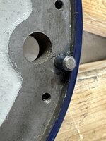
Its critical when installing the idler shafts that the hole for the locking set screw is facing down and the pin for the bearing retainer plate is facing up, so I took some time to ensure I had it properly aligned prior to driving it in. I used a thin sharpie marker to mark the top center line to aid in this.
IMG_9368.jpeg
I then started to drive the forward idler stud in, until it was just proud of the casting.
IMG_9371.jpeg
I could then slide the rear bearing retainer plate on. The groves face, faces the bearing. Their is a notch on its center bore that must align with a pin on top of the idler shaft.
IMG_9372.jpeg
I then used a long brass drift to further drive the stud in, so I cloud slip the gear on,
 
OP
G

Grant Gunderson

Well-known member
Joined
May 17, 2013
Messages
2,323
Location
Bellingham, WA
IMG_9373.jpeg
and then a bit more to mount the forward bearing retainer plate. One again the grooved side faces into the bearing.
IMG_9375.jpeg
Here you can see the splash gear assembly fully installed on to the idler stud.

IMG_9380.jpeg
The stud is in the correct position once it's in flush with the rear of the casting.
IMG_9382.jpeg
I used a long pin punch to ensure I had the stud's recess aligned for the dogpohint locking setscrew that goes in from the bottom of the headstock casting.
IMG_9383.jpeg
IMG_9385.jpeg
Because it will be a real ***** to access these latter incase they loosen up, I added a hollow locking set screw behind the dogpoint.
IMG_9377.jpeg
A screw starter aided in getting the log dog point set screw for the tachometer splash gear retainer started with out dropping it into the casting.
IMG_9379.jpeg
I then torqued the setscrew down.
IMG_9388.jpeg
The shifter fork rack shaft then can be slid in. Their is a factory dot witness mark that faces the bed side of the gear box.
IMG_9390.jpeg
The rear berating retainer plate for the idler gear goes on next. Grooved Sade facing the bearing, its bore notch will need to align with a pin top center of the idler gear stud when it gets installed latter.
 
OP
G

Grant Gunderson

Well-known member
Joined
May 17, 2013
Messages
2,323
Location
Bellingham, WA
IMG_9392.jpeg
The idler gear goes on next. Note the orientation of the gear!
IMG_9394.jpeg
Followed by the forward bearing retainer with its grooved face, facing the bearing.
IMG_9395.jpeg
The rack shaft and idler gear now need to get slid all the way forward towards the bed end of the gear box.
IMG_9349.jpeg
The rear idler stud had a factory pressed in center plug, that was a real pain in the *** to remove to get the idler stud out on disassembly, so I decided to drill it out to accept a ¾" pipe tap. Now I could have used a smaller size, but there is a method to the madness. After drilling, it I used a ¾ Pipe tapper reamer to taper the bore.
IMG_9350.jpeg
Followed by a ¾ NPT pipe tap.
IMG_9351.jpeg
I can now test fit the brass pipe plug that I ordered from McMaster... this just so happens to have an inner thread that matches my slide hammer if I ever need to remove it again.
IMG_9354.jpeg
The index pin on the idler shaft for the rear idler gear retaining plate got mangled in the vise on the Bridgeport, so I tapped it out and replaced it.
IMG_9396.jpeg
That index pin needs to face top center, so I took my time to align the idler stud prior to driving it in.
IMG_9400.jpeg
I used a larger bearing drift to tap it in.
IMG_9402.jpeg
The idler stud needs to be flush with the casting.
 
OP
G

Grant Gunderson

Well-known member
Joined
May 17, 2013
Messages
2,323
Location
Bellingham, WA
IMG_9410.jpeg
I had to unbolt the headstock and lit and one it back to access the hole for the dog point set screw that locks the idler stud in place. It also got a locking hollow set screw. I then replaced the headstock casting into the correct position and locked it down to the bed.
IMG_9411.jpeg
I then used a socket to screw the brass pipe plug into the idler stud.
IMG_9412.jpeg
Followed by the screw plug for its center hole.

The idler stud / rack shaft installation is now fully complete. Note I didnt lock the idler gear retainer plate down on purpose. It needs to remain loose for now.
 
OP
G

Grant Gunderson

Well-known member
Joined
May 17, 2013
Messages
2,323
Location
Bellingham, WA
Next for installation is the reverse shaft.
IMG_9417.jpeg
Note, I show the shat facing the wrong direction here!
IMG_9421.jpeg
The right hand (bed side) bearing is a New Depatrue 43204. I was able to find new old stock online that had the correct snapring on it. It's critical that this bearing is either flanged or has a snapring.
IMG_9428.jpeg
It gives driven in with the snapring locating it. Note the pink paint plug on the side of the casting I had forgotten to remove!
IMG_9429.jpeg
When I took the headstock apart, I am really glad I scribed on each gear its orientation, so I didnt mix them up. Still visible after they came out of the ultrasonic.
IMG_9432.jpeg
I then dropped the gears into the casting.
IMG_9435.jpeg
I could then slide the reverse shaft in and through the gears.
IMG_9438.jpeg
With the shaft fully seated into the front bearing, I could then mesh the left side gear with the idler gear. Note, its best to not install any of the set screws yet on any of the gears, they need to be left loose.
IMG_9445.jpeg
The reverse shaft originally used a Victor 60250 oil seal. It's 44.5" OD, 1MM thick and the shaft is 25MM. Its not a common size. Based upon a post I found on PM, I ordered two of these. AVX #TC25x44.5x6.
IMG_9447.jpeg
I used the arbor press to install them into the bearing retainer plate.
IMG_9450.jpeg
With two seals I doubt it will leak!
 
To avoid these ads, REGISTER NOW!
OP
G

Grant Gunderson

Well-known member
Joined
May 17, 2013
Messages
2,323
Location
Bellingham, WA
IMG_9452.jpeg
The end gear side of the reverse shaft gets a new old stock New Departure 52050 Bearing. I slid it onto the reverse shaft.
IMG_9453.jpeg
and then used the bearing retainer plate to press the bearing in using its SHCS. The reverse shaft and gears are now fully installed. I now need to install the gear box back into the lathe.
IMG_9456.jpeg
I chased all 4 of its mounting holes and applied Tef-Gel to them.
IMG_9460.jpeg
The gear box is heavy but I was able to slide it in by myself.
IMG_9462.jpeg
It gets retained by 4 7/16-14 SHCS. they are 5 and 5.5" in length. The longer bolts go on the bottom.
 
Last edited:
OP
G

Grant Gunderson

Well-known member
Joined
May 17, 2013
Messages
2,323
Location
Bellingham, WA
The Left hand / Feed / Right Hand selector gets installed next.
IMG_9548.jpeg
I started by using a 1"-16 tap to chase the threads for the packing nut.
IMG_9475.jpeg
In order to properly install the packing, the bushing on the feed selector shaft needs to be removed. its held in place by a tapper pin.
IMG_9477.jpeg
I then wrapped the packing around the shaft.
IMG_9478.jpeg
and cut it with an exacto knife
IMG_9479.jpeg
The packing is now ready to be installed.
IMG_9480.jpeg
The feed selector shaft slides in first.
IMG_9481.jpeg
I then loosely assembled the feed sector housing
IMG_9484.jpeg
and checked I had proper alignment with the shaft and the rack gear. I then removed the housing assembly.
IMG_9486.jpeg
The packing gets wrapped around the shaft and then tapped in. I clocked each section of packing, so none of the cuts align.
IMG_9487.jpeg
I then start the packing nut
 
OP
G

Grant Gunderson

Well-known member
Joined
May 17, 2013
Messages
2,323
Location
Bellingham, WA
IMG_9549.jpeg
I found this tool in the tooling that came with the lathe. It's a packing nut wrench! It slides over the shaft and has two tabs that tighten the nut. The nut needs to be installed at a minimum to be flush with the casting.
IMG_9552.jpeg
I then reinstall the bushing on the feed selector shaft and drive its tapper pin back in after I reamed the hole. I also installed two tapper pins into the head stock casting that align the feed selector housing
IMG_9554.jpeg
The feed selector housing gets installed with 3 SHCS, and the back plate for the knob index gets installed with 3 SHCS
IMG_9555.jpeg
The plate then gets installed with 3 oval head screws. Note, I will need to send it in for chrome when I get the rest of the pieces done.
IMG_9556.jpeg
The woodruff key then gets tapped into place.
IMG_9557.jpeg
The knob slides on
IMG_9558.jpeg
It's spring then goes in next
IMG_9559.jpeg
and it then gets retained by its large snake eye screw.
IMG_9561.jpeg
I then chased the holes for the index plate and applied some Ted-Gel to it.
IMG_9563.jpeg
The index plate gets installed and the index rod slid in.
 
OP
G

Grant Gunderson

Well-known member
Joined
May 17, 2013
Messages
2,323
Location
Bellingham, WA
Up next is the spindle clutch gears.
IMG_9568.jpeg
The bushings for mine are very worn. I really need to find some replacements. Here you can see how worn the LH gear bushing is.
IMG_9569.jpeg
It's surface finish is extremely rough.
IMG_9572.jpeg
Here you can see galling on the gear's shaft. I suspect a set screw or something made its way in there and got ground down.
IMG_9573.jpeg
I used a stone to remove the high spots and smooth out the surface finish best I could on both pieces. Not ideal, but will hopefully work until I can find replacement parts.
IMG_9575.jpeg
At least it looks better now.
IMG_9590.jpeg
I gave all of the parts a good coating of oil and slid them together. There at least feel smooth when I rotate them now.
IMG_9594.jpeg
The retaining ring and a double dot witness mark that makes its alinement. The way the holes are drilled, it will only sign up the correct way. It is then retained by 4 ¼-20 dog point set screws.

IMG_9598.jpeg
In order to install the LH spindle clutch gear, the idler gear needs to be slid all the way towards the bed of the lathe.
IMG_9604.jpeg
In order to press the LH spindle clutch gear and its bushing it, I used some parts out of a wheel bearing press kit to align the screw I used.
IMG_9606.jpeg.Here is my setup. Note the ¼" Parallel used to hold the plate flush against the clutch side of the gear. The indent for the large dog point set screw that retains the bushing needs to be located top center as well.
 
OP
G

Grant Gunderson

Well-known member
Joined
May 17, 2013
Messages
2,323
Location
Bellingham, WA
IMG_9608.jpeg
With the left hand clutch gear pressed in, I could then finally align the lower idler gear, and the left hand reverse gear. and then tighten the set screws that retain each of them.
IMG_9610.jpeg
IMG_9614.jpeg
The LH clutch bushing then gets retained with a large dog point set screw and a second locking set screw.
IMG_9615.jpeg
I can then install the inner bushing for the LH clutch gear. Its got a Factory "D" witness mark that faces the end gear side.
IMG_9617.jpeg
The RH spindle clutch gear and bushing assembly was in much better shape. It goes together the same way as the left hand.
IMG_9618.jpeg
It only has a single dot witness mark to identify the location of its retaining ring. Once again it uses 4 ¼-20 dog point set screws.
IMG_9619.jpeg
To press it in I used the same wood plate I made for removing the spindle.
IMG_9620.jpeg
Here you can see the parallel I used to to keep the clutch side pressing in flush. The recess for its locking set screw must face top center as well.
IMG_9623.jpeg
While pressing it in, I meshed the RH reverse gear with it.
IMG_9627.jpeg
Once it was fully pressed in, I secured the RH reverse gear with its dogpohint set screw.
 
OP
G

Grant Gunderson

Well-known member
Joined
May 17, 2013
Messages
2,323
Location
Bellingham, WA
IMG_9629.jpeg
and then the large dog point set screw that secures the RH clutch bushing.
IMG_9630.jpeg
and then its locking set screw.
IMG_9631.jpeg
the sifter fork then got a coat of oil
IMG_9632.jpeg
it uses locking washers.
IMG_9636.jpeg
It then gets installed with two different length SHCS, with the tall end of the shifter fork on the end gear side.
IMG_9642.jpeg
The clutch gear then drops into place.
 

DocsMachine

Well-known member
Joined
Sep 16, 2006
Messages
1,868
If anyone out there is thinking this is a complex machine... keep in mind somebody designed this thing with no computer, no CAD, no AI, just a sheet of paper, a pencil and a slide rule. :)

The parts were made on what were basically manual machines- "automated" only by motors and gears- and the iron parts were largely poured by hand.

All of which was some eighty years ago.

Keep it comin' Mr. G! Lovin' every minute of it.

Doc.
 
OP
G

Grant Gunderson

Well-known member
Joined
May 17, 2013
Messages
2,323
Location
Bellingham, WA
Next on the installation list is the tachometer.
IMG_9643.jpeg
The inner bezel just pulls off, the outer bezel is retained by 3 screws.
IMG_9646.jpeg
The needles just pulls off of the front. I'm going to repaint it and get a new background printed for the gauge.
IMG_9647.jpeg
The gauge just lifts off of the front, it has 4 tabs that locate it.
IMG_9648.jpeg
The spring that steadies the needle movement is incredibly delicate but its in good shape. It's about the only thing on the lathe that I'm not going to F with.
IMG_9651.jpeg
On the back of the tachometer, there is a bronze bushing that holds the drive shaft for it. The shaft isn't spinning freely in it. I am going to address this.
IMG_9653.jpeg
I used my bench block and pin punch to tap it out.
IMG_9656.jpeg
I then chucked a .001" over sized reamer into my vise and twisted the bushing on, to remove the burrs that where causing the shaft to bind.
IMG_9668.jpeg
I cleaned the inner surfaces up and put it back together. Note the felt ring on the drive shaft that engages the input drive on the tach.
IMG_9669.jpeg
I then threaded the bushing back in.
IMG_9670.jpeg
I then cut a new gasket for the back of the main bezzle
 
OP
G

Grant Gunderson

Well-known member
Joined
May 17, 2013
Messages
2,323
Location
Bellingham, WA
IMG_9671.jpeg
The main bezel then gets reattached.
IMG_9674.jpeg
The mounting studs on the back unthread from the unit. I cleaned them up and reinstalled.
IMG_9675.jpeg
and cut a new cork gasket for the back. I sett aside until I get the tachometer bracket installed.
IMG_9682.jpeg
Here is the layout of the tachometer bracket and the taster shaft.
IMG_9683.jpeg
an 8-32 dogpohint set screw holds the bevel gear on to the shaft.
IMG_9685.jpeg
I chased the threads prior to installing it.
IMG_9686.jpeg
The set screw only gets lightly tighten until the main drive gear is added to the shaft. Its a very precise fit.
IMG_9691.jpeg
This has to be assembled after its in the head stock casing, but this gives an idea of how in needs to go together.
IMG_9695.jpeg
I used some bent tip needle nose pliers to hold the drive gear in place.
IMG_9699.jpeg
I then slid the transfer shaft into it, and inserted the pin using the bent needle nose pliers again.
 
OP
G

Grant Gunderson

Well-known member
Joined
May 17, 2013
Messages
2,323
Location
Bellingham, WA
IMG_9703.jpeg
The pin needs to fit in flush to its recess.
IMG_9705.jpeg
A cotter pin gets inserted into it to retain it.
IMG_9706.jpeg
and its end tabs get properly secured over. I tested that it all rotates smoothly. The bevel gear we installed earlier get gets it's dogpoint set screw fully tightened down.
IMG_9707.jpeg
The bracket can now be installed. It gets located by two threaded tapper pins.
IMG_9709.jpeg
I drove them in with a large brass drift.
IMG_9711.jpeg
It finally gets secured buy 2 SHCS.
IMG_9678.jpeg
The tachometer can now be inserted.
IMG_9679.jpeg
IT is a very snug fit. I drove it in using a large socket that fit over the inner mechinism.
IMG_9715.jpeg
With it partially inserted the drive gear for the tachometer input shaft goes on next.
IMG_9716.jpeg
Once its secured with a 8-32 dog point set screw,
 
OP
G

Grant Gunderson

Well-known member
Joined
May 17, 2013
Messages
2,323
Location
Bellingham, WA
IMG_9680.jpeg
I can then drive the tachometer the rest of the way in.

IMG_9717.jpegIt get secured by a set screw.
IMG_9719.jpeg
The only way I could tighten the next two nuts was to use an ignition wrench.
IMG_9718.jpeg
They were very difficult to get secured. I placed a magnet bellow them to keep them from dropping into the casting.
 
OP
G

Grant Gunderson

Well-known member
Joined
May 17, 2013
Messages
2,323
Location
Bellingham, WA
Next up is the rear spindle bearing.
IMG_9723.jpeg
The factory one was open on both sides. It wa a New Departure 5210
IMG_9724.jpeg
It is getting replaced with a brand new New Departure 5510. Its the same bearing but is shielded on one side.
IMG_9721.jpeg
My first attempt at a gasket for the rear bearing plate. This one was too thin. So I ended up cutting one out of much thicker stock.
IMG_9722.jpeg
The oil slinger gets installed, once again before I figured out I need a thicker gasket. Note, there is an oil return hole that I also needed to cut on the thicker gasket at the bottom.
IMG_9726.jpeg
The bearing retainer and oil slider presses the bearing back in.
IMG_9727.jpeg
The bearing retainer plate, with oil slinger and thicker gasket installed. The short marker mark at the bottom 06.10" mark shows where the oil return passage is. If you use too thin of a gasket it applies too much pressure to the bearing to spin freely.
 
OP
G

Grant Gunderson

Well-known member
Joined
May 17, 2013
Messages
2,323
Location
Bellingham, WA
Next up is installation of the front bearing stack on the spindle!
IMG_9729.jpeg
Mine has a "T" fitters mark on it.
IMG_9730.jpeg
I used a marker to highlight the factory witness scribe lines. These are critical for proper bearing alignment.
IMG_9734.jpeg
First, notice the oil drain holes on the back of the front plate. I then cut a gasket to fit and cut out holes for the drains.
IMG_9733.jpeg
The front retainer slides on to the spindle
IMG_9736.jpeg
followed by the front bearing, making sure its aligned with both of the factory scribe marks, and then the inner bearing race spacer.
IMG_9739.jpeg
The outer race spacer goes on next. once again its crucial these are aligned with the factory marks.
IMG_9740.jpeg
And then the upper bearing. Its also important the go on facing the right direction as these are duplex bearings and the races are ground to work together this the spacers for the proper preload. The bearings do not need to be pressed onto the shaft.
IMG_9743.jpeg
The rear bearing retainer bushing then goes on, once again aligning it with the factory witness marks. I can then install the bearing lock nut, but I am having issues with this threads binding. I need to order a new bearing retaining nut.
 
Last edited:
OP
G

Grant Gunderson

Well-known member
Joined
May 17, 2013
Messages
2,323
Location
Bellingham, WA
Since I need to wait for the new bearing nut to arrive to finish the spindle, I'm going to finish up the Apron.
IMG_9760.jpeg
I ordered new copper tubing from Fluidline systems. I should have used copper in the first place instead of the brass. It's 100X's easier to work with!
IMG_9761.jpeg
I first ran the line to determine the proper lengths.
IMG_9762.jpeg
I then used a brake line flaring tool to flair the ends for the reservoir side.
IMG_9773.jpeg
Not the best pic, but the copper flares way better than the brass too. It's just way more malleable.
IMG_9764.jpeg
the other end that goes into the T fitting gets reamed
IMG_9765.jpeg
The compression nut goes on
IMG_9766.jpeg
the olive goes on next
IMG_9768.jpeg
and the inner ferrule goes in last. Bijur fittings are all compression fittings but with very odd ball sizing. Like all compression fittings they seal buy the nut clamping down on the olive, which is why having the inner ferrule is important so it doesn't just collapse the tube.
IMG_9771.jpeg
I connected the fittings to the Tee. What s really annoying about Bijur fittings is some of them use a metric 10mm wrench and others use a ⅜.... very odd. Note the meter unit on the line that goes from the T to the reservoir. The brass line is from the pump in the bottom of the apron, it pushes oil into the T where the metered flow goes into the reservoir and the non-metered flow goes into the carriage.
IMG_9774.jpeg
For the lines that fed oil to the friction levers, I used a tube bender to make the bends.
 
OP
G

Grant Gunderson

Well-known member
Joined
May 17, 2013
Messages
2,323
Location
Bellingham, WA
IMG_9779.jpeg
I then used some RTV sealant to make sure they dont leak at the reservoir. Finally I added some new feet to the reservoir.
IMG_9780.jpeg
With the lines done I can now finally install the half nuts. First the half nut arms and bushing assembly go in.
IMG_9782.jpeg
Followed by the half nut studs
IMG_9783.jpeg
and then the bronze half nuts
IMG_9784.jpeg
the heavy washers go on next, with the beveled edge side facing out.
IMG_9785.jpeg
The heavy nuts used on the half nuts have one side that is machined. This faces the washers.
IMG_9786.jpeg
I then torqued them down and ensured they operated smoothly.
IMG_9788.jpeg
The interlocking bar goes into the half nut bracket in this orientation.
IMG_9789.jpeg
I could then toque down the half nut brackets.
 

RickP

Well-known member
Joined
Jan 15, 2013
Messages
1,552
Location
Annapolis, MD
Great job on an incredibly complex assembly procedure. Those blue painted parts really pop in the photos -- I can't wait to see it all back together.

I don't think I'd have the patience to tackle something this complex.
Do you have a background in machine assembly or is this skill a self-taught hobby?
 
OP
G

Grant Gunderson

Well-known member
Joined
May 17, 2013
Messages
2,323
Location
Bellingham, WA
Great job on an incredibly complex assembly procedure. Those blue painted parts really pop in the photos -- I can't wait to see it all back together.

I don't think I'd have the patience to tackle something this complex.
Do you have a background in machine assembly or is this skill a self-taught hobby?
No background in machine assembly other then when I bought my Bridgeport mill and tore it down to the last screw to restore it. It's a fully self taught hobby that originated out of the desire to have nice tools but limited budget. In both cases I bought the machines cheap and then poured some sweat equity into them. The nice thing about taking a machine fully apart and rebuilding it, is you develop a really good understanding of how it actually works. I've probably learned more from the lathe project. alone then I did the entire 7 years I spent earning my Engineering Degree.
 

fartymarty

Well-known member
Joined
Nov 9, 2012
Messages
1,348
Location
Fort Worth
No background in machine assembly other then when I bought my Bridgeport mill and tore it down to the last screw to restore it. It's a fully self taught hobby that originated out of the desire to have nice tools but limited budget. In both cases I bought the machines cheap and then poured some sweat equity into them. The nice thing about taking a machine fully apart and rebuilding it, is you develop a really good understanding of how it actually works. I've probably learned more from the lathe project. alone then I did the entire 7 years I spent earning my Engineering Degree.

The thought that continuously pops into my head as I admire your rebuilding skills and attention to detail...is that some people (engineers I suspect) actually sat down with pen and paper and designed this machine. Sure there was probably some trial and error, and modifications from earlier designs..but still 90% of the design is probably from the original right?
I wouldn't short sell your 7 years of training. I'm constantly amazed by what engineers are able to come up with simply with pen and paper. I can fabricate stuff in my garage by trying and bending and reworking stuff by trial and error and make modifications but I can never just sit down and draw stuff that will work ..at least not until after I build it.

Thanks for sharing with us!
 

DocsMachine

Well-known member
Joined
Sep 16, 2006
Messages
1,868
It's not as complex, but I have to say I was impressed when I rebuilt my '39 Warner & Swasey turret lathe. Those guys knew how to build a machine that lasts. Mine's eighty-plus years old, and has certainly made hundreds of thousands of parts- and save for a few places, it's still tight as a drum.

The turret locking mechanism is solid as a rock, there's zero play in the spindle, there's no appreciable wear in the collet mechanism (originally a motorized, power collet closer, which I converted to manual since the motor was missing) the sliding ways for the turret ram are smooth as glass and show very little wear (although they're replaceable, and it's certainly possible they were at some point replaced) the power feed gear drive for the ram works smoothly and perfectly in all gears, the feed clutch works perfectly...

Compare something like that, or Grant's 10EE, to even a $10K modern import, and it's night and day.

Doc.
 
To avoid these ads, REGISTER NOW!
Top Bottom