Thank you for your reply.
Unfortunately wall switch is not wired at all.
Do you have any other idea how to identify that position on the controller?
What model is your opener?
Thank you for your reply.
Unfortunately wall switch is not wired at all.
Do you have any other idea how to identify that position on the controller?
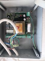
The diagram is different from what is pictured in the fist post of this thread.... However, if I had to GUESS, I d say the two switch terminals are the two terminals in the lower right hand corner of the box that shows a "switch" symbol directly above the terminal block.
See my picture below. The red circle is probably the switch the terminal block, and the blue arrow points to the "switch" symbol on the circuit board. Again, this is all just a guess.... verify for yourself. Don't take my word for it.
Thanks, I'll tryIt should just be10 & 11.
Edit: You have the wrong schematic. It should be 8 & 9.
Okay.... I have no idea what the differences are between the two model of openers that you just mentioned. I only know that the diagram that was posted does NOT represent the picture that is posted. Where would 10 & 11 (or 8 & 9) be located in the PICTURE he posted? I am assuming the PICTURE he posted is the actual piece of equipment that he's working on.OP has a DREAM not a MISE RI.
The terminals in your picture are outputs.
Should be 8 & 9!
Okay.... I have no idea what the differences are between the two model of openers that you just mentioned. I only know that the diagram that was posted does NOT represent the picture that is posted. Where would 10 & 11 (or 8 & 9) be located in the PICTURE he posted? I am assuming the PICTURE he posted is the actual piece of equipment that he's working on.
Again, I was just guessing. Trying to help. If I was wrong..... then I was wrong. Just like I figured.
Okay.... well, that makes a big difference. Just as I said, the wrong diagram was posted. Having the correct diagram makes all the difference in the world. Thanks
Thanks! So 2 wires from OP will connect to 8&9