To avoid these ads, REGISTER NOW!

Garage wifi controller wiring

ocemioce

Member
Joined
Dec 3, 2023
Messages
7
I bought RSH SB003 universal smart/Wifi garage door opener control set and have no idea how to wire it on the control panel.
Controller is Beninca MISE RI:
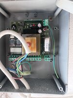
IMG_7011.JPG

It says I need to connect it to a wall switch, but don't know where is it on the controller.
Would appreciate if someone could help.
Thanks
 
To avoid these ads, REGISTER NOW!

justsam

Well-known member
Joined
Aug 20, 2010
Messages
1,268
Location
Penngrove, California
Where is the wall switch today? This is typically a push button momentary switch used to manually open or close the door or gate. There should be two wires here that connect back to the Beninca unit. The Wifi controlled switch should just connect in parallel with the existing wall switch. This could be done at the switch or at the Beninca unit.
 
OP
O

ocemioce

Member
Joined
Dec 3, 2023
Messages
7
Thank you for your reply.
Unfortunately wall switch is not wired at all.
Do you have any other idea how to identify that position on the controller?
 

BrandonV

Well-known member
Joined
Jun 9, 2023
Messages
4,030
Location
Arizona
Thank you for your reply.
Unfortunately wall switch is not wired at all.
Do you have any other idea how to identify that position on the controller?

It should just be 10 & 11.

Edit: You have the wrong schematic. It should be 8 & 9.
 
Last edited:

AA/FC

Well-known member
Joined
Dec 9, 2010
Messages
2,080
The diagram is different from what is pictured in the fist post of this thread.... However, if I had to GUESS, I d say the two switch terminals are the two terminals in the lower right hand corner of the box that shows a "switch" symbol directly above the terminal block.

See my picture below. The red circle is probably the switch terminal block, and the blue arrow points to the "switch" symbol on the circuit board. Again, this is all just a guess.... verify for yourself. Don't take my word for it.
 

Attachments

  • switch.png
    switch.png
    4 MB · Views: 13
Last edited:
To avoid these ads, REGISTER NOW!

BrandonV

Well-known member
Joined
Jun 9, 2023
Messages
4,030
Location
Arizona
The diagram is different from what is pictured in the fist post of this thread.... However, if I had to GUESS, I d say the two switch terminals are the two terminals in the lower right hand corner of the box that shows a "switch" symbol directly above the terminal block.

See my picture below. The red circle is probably the switch the terminal block, and the blue arrow points to the "switch" symbol on the circuit board. Again, this is all just a guess.... verify for yourself. Don't take my word for it.

OP has a DREAM not a MISE RI.

The terminals in your picture are outputs.

Should be 8 & 9!
 

AA/FC

Well-known member
Joined
Dec 9, 2010
Messages
2,080
OP has a DREAM not a MISE RI.

The terminals in your picture are outputs.

Should be 8 & 9!
Okay.... I have no idea what the differences are between the two model of openers that you just mentioned. I only know that the diagram that was posted does NOT represent the picture that is posted. Where would 10 & 11 (or 8 & 9) be located in the PICTURE he posted? I am assuming the PICTURE he posted is the actual piece of equipment that he's working on.

Again, I was just guessing. Trying to help. If I was wrong..... then I was wrong. Just like I figured.
 

BrandonV

Well-known member
Joined
Jun 9, 2023
Messages
4,030
Location
Arizona
Okay.... I have no idea what the differences are between the two model of openers that you just mentioned. I only know that the diagram that was posted does NOT represent the picture that is posted. Where would 10 & 11 (or 8 & 9) be located in the PICTURE he posted? I am assuming the PICTURE he posted is the actual piece of equipment that he's working on.

Again, I was just guessing. Trying to help. If I was wrong..... then I was wrong. Just like I figured.

Good observation and good lesson in double checking. I trusted the OPs schematic!

Thanks for pointing it out.
 
To avoid these ads, REGISTER NOW!
Top Bottom