To avoid these ads, REGISTER NOW!

Snap-On WB250 Wheel Balancer repair?

RallyKeith

Member
Joined
Apr 13, 2016
Messages
17
Location
Reading, PA
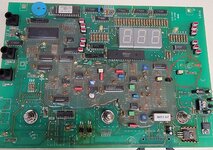
I bought a used Snap-On WB250 wheel balancer a few months ago and it worked flawlessly for the first month or so. Then it started to misbehave. No matter how out of balance a wheel you put on it, it comes up as perfectly balanced. Initially it would begin working after being left plugged in and turned on for about 10 minutes. Now it never works. I'm an electronics technician and this screams of a bad electrolytic capacitor somewhere. Does anyone have any experience with this? My local snap on guys says good luck. No support or parts for something this old. Any help is appreciated.

Thanks,
Keith
 
To avoid these ads, REGISTER NOW!
OP
R

RallyKeith

Member
Joined
Apr 13, 2016
Messages
17
Location
Reading, PA
With no repair info, about all you can do is take it apart and look for bad connections, burned components and pregnant caps.

There is another thread here, but probably not useful
http://www.garagejournal.com/forum/showthread.php?t=193908

Yeah, I saw that thread. Nothing on the control board looks out of shape. measured across a few of the electrolytic caps to make sure none of them were completely shot and all seemed ok, no signs of venting of bloating. Going to take a look at the measurement head assembly sometime this week.
 
OP
R

RallyKeith

Member
Joined
Apr 13, 2016
Messages
17
Location
Reading, PA
Well, I pulled off the sensor assembly and other than a little dirt everything looked good. The timing wheel was in great shape and all the wiring to the sensors and brake solenoid were in good shape with no nicks or pinching. I reassembled it and tried it. Started off always showing 000. After a few minutes and a few spins it started working. Still seems like its a bad cap somewhere. The issue is that the board is coated in clear RTV. I'll have to pull it out and do some real troubleshooting. I'm an electronics technician so that's no big deal.
 

WhiffySpark

Well-known member
Joined
Oct 22, 2009
Messages
6,252
John beam makes them I think. I doubt it's hunter but it may be. I'd try calling a repair guy they may have an idea
 

engineer2

Well-known member
Joined
Dec 13, 2009
Messages
11,824
Location
Chicago burbs
At least caps are easy to check and cheap to replace. Same with rectifiers and diodes. I've fixed a few things simply by re-soldering suspicious looking solder connections. From what you say, it might make sense to start with the power supply side, but I'm sure you know that already.
 
OP
R

RallyKeith

Member
Joined
Apr 13, 2016
Messages
17
Location
Reading, PA
At least caps are easy to check and cheap to replace. Same with rectifiers and diodes. I've fixed a few things simply by re-soldering suspicious looking solder connections. From what you say, it might make sense to start with the power supply side, but I'm sure you know that already.

Not having a schematic makes it difficult to do proper trouble shooting. It's powered by a 9.8 VAC wall transformer so the power supplies shouldn't be very complicated. With the way it powers up and all the displays function it makes me think there might be two supplies, one for the display and processing and one for the measurement interface since it appears to use two load cells/strain gauges to measure the vibration.
 

engineer2

Well-known member
Joined
Dec 13, 2009
Messages
11,824
Location
Chicago burbs
That makes sense. Load cells need a stable and regulated "excitation voltage" to operate. If the load cells are a "full bridge" they will have 4 wires, 2 wires will be for the excitation power and 2 will be for the signal. There are also half and quarter bridges. Wiring examples are plentiful online.
 

ukateshka

Active member
Joined
Jun 12, 2024
Messages
29
I bought a used Snap-On WB250 wheel balancer a few months ago and it worked flawlessly for the first month or so. Then it started to misbehave. No matter how out of balance a wheel you put on it, it comes up as perfectly balanced. Initially it would begin working after being left plugged in and turned on for about 10 minutes. Now it never works. I'm an electronics technician and this screams of a bad electrolytic capacitor somewhere. Does anyone have any experience with this? My local snap on guys says good luck. No support or parts for something this old. Any help is appreciated.

Thanks,
Keith
Same here, I just bought WB250A and it shows 000. I disassembled it, cleaned and checked, the control board has some suspection components there was oxidation between feet, cleaned and resoldered but still the problem didn't go a way.
 
Last edited:

ukateshka

Active member
Joined
Jun 12, 2024
Messages
29
Same here, I just bought WB250A and it shows 000. I disassembled it, cleaned and checked, the control board has some suspension components there was oxidation between feet, cleaned and resoldered but still the problem didn't go a way.
 

Attachments

  • 20240614_231852.jpg
    20240614_231852.jpg
    1.1 MB · Views: 72
  • 20240614_231616.jpg
    20240614_231616.jpg
    851.2 KB · Views: 74

ukateshka

Active member
Joined
Jun 12, 2024
Messages
29
There're two LED that show where to install weights, they don't work as well. Can that be because of bad microchip I showed above?
 

rlitman

Well-known member
Joined
Oct 18, 2010
Messages
24,650
Location
Long Island
It's beeping like usually when reaching the required speed, and then continue spinning a bit and it's automatically breaks, then it shows zeros.
Ok, well that's a good sign, because that means the board is reading the tachometer and has decided the wheel is spinning at the right rate (the beep), and evenly enough that it's in balance. Obviously it isn't in balance, but it does mean quite a bit must be working.

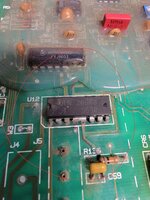
If it were me, I'd start with the basics of ruling out the most likely failures before moving to full-on diagnostics, but since you've taken a shine to that darlington quad transistor, pins 4&5 (the two bridged lower middle ones in your picture) should both go to ground. So should pins 12&13 (directly opposite). Pin 14 (top row, third from left) should be getting 10V in. I'm not sure what they're using that component for (I'd need to spend much more time staring at both sides of the board), but it does seem like the sort of thing you'd use to amplify a signal from a load cell, and if so, move on, because the load cell input is ONLY used for dynamic balance, and this machine is failing on static.

1) sniff and look around for any signs of overheating (nothing stands out in your picture, but take a close look anyway)

2) look closely (use a magnifier if you must) at every electrolytic capacitor to for signs of bulging (could be either end dome, so either the top, or the cap is sitting unusually high) or leakage

3) move onto the variable resistors. I'm hoping your problem is actually here. Variable resistors oxidize on the contact surfaces with age, and that can make them appear to be an open circuit. If the computer thinks your wheel is infinitely large in diameter (so start with the diameter resistor), it might think that an perceived imbalance would require a weight under the minimum correction. Though I'm still pretty sure the machine would light up the location up/back arrows, even on 000, so my above hope comes with a low degree of confidence.

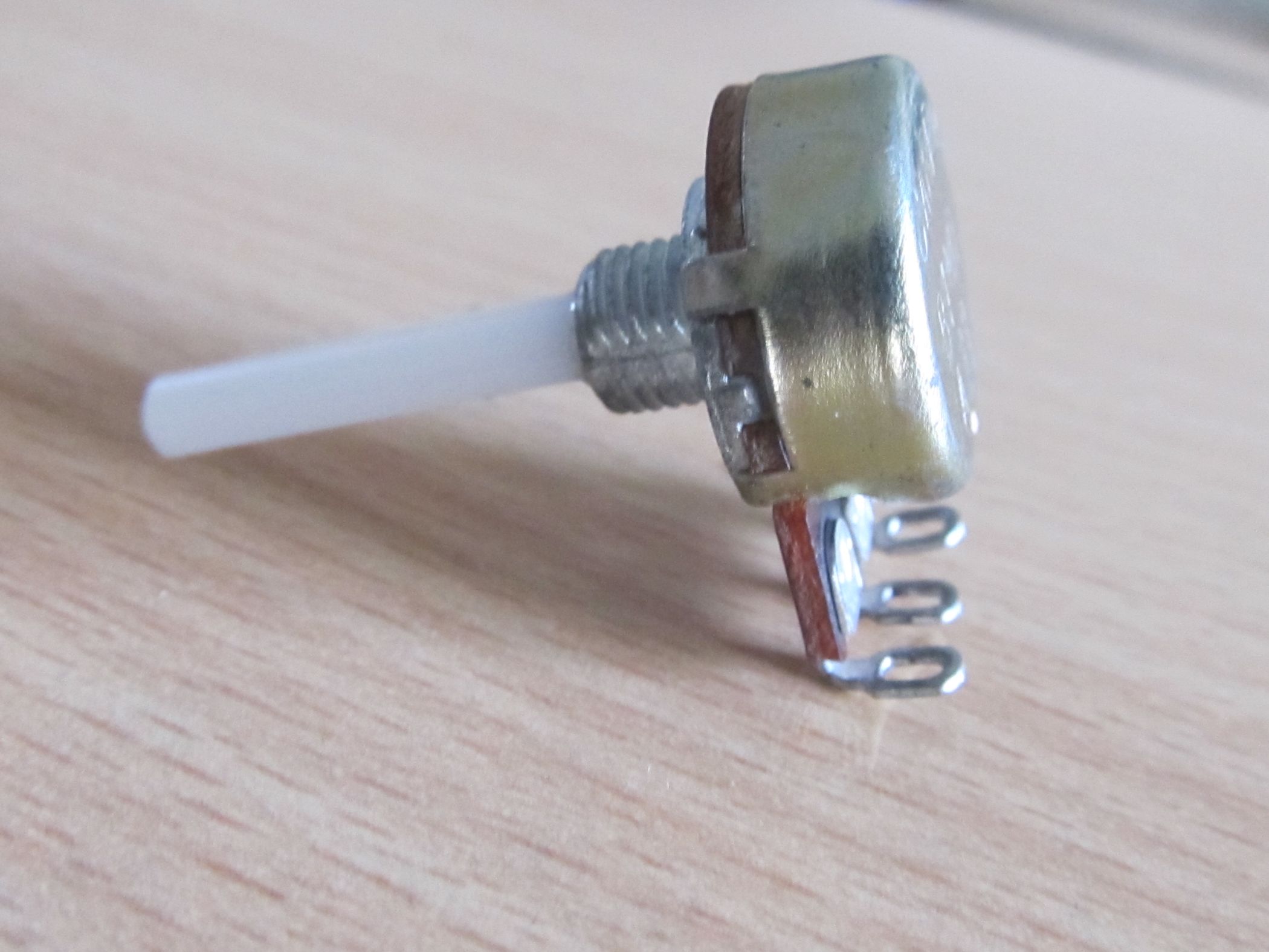
Anyway, with variable resistors (potentiometers), you should be able to read the markings on the cans and get the specs, and them ohm them in-circuit. Measure across the two outer leads for sanity check (it should be a lower resistance than the resistor's max, because it's in-circuit), then measure between each outer and the center as you sweep the dial. If it isn't going up and/or down across the range, then you've found your issue.

4) move onto power tracing. See if you can figure out how power is converted from the AC input to the DC for the logic, and make sure it's getting there (though it probably is, since you get the beep).
 

ukateshka

Active member
Joined
Jun 12, 2024
Messages
29
These spots have signs of overheating, the grill is actually getting very hot, I'm assuming it's supposed to be like that. Also I measured the output of the power supply and it gives me 10.09V but on DC adapter says 8.5V is that normal?
1000012692.jpg
 

gregs

Well-known member
Joined
Mar 16, 2007
Messages
1,603
Probably just the picture, but the cap on the right side that is running vertically and on its side looks a little puffy. Without a schematic your just guessing. The other thing to do is to remove components and test looking for ones that look heat stressed. Did someone spill the coating on the board? I have never seen one that was partially coated like that. Have you goggled the numbers on the board? Seems like a power supply issue but who knows. Having a bad cap can cause a filter problem that does affect other components. Have you tried a different wall wart?
 

ukateshka

Active member
Joined
Jun 12, 2024
Messages
29
Yeah, there's RTV coating on both sides like that, probably just to protect the components. That cap looks good. I wish I could have the schematic for this board, the internet shows nothing when I Google. No, I have not tried a different power supply.
 

rlitman

Well-known member
Joined
Oct 18, 2010
Messages
24,650
Location
Long Island
These spots have signs of overheating, the grill is actually getting very hot, I'm assuming it's supposed to be like that. Also I measured the output of the power supply and it gives me 10.09V but on DC adapter says 8.5V is that normal?
The power supply being a little off shouldn't matter. These were meant to be portable units that could run off a 12V battery track-side.

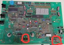
The four vertical diodes in your left circle are a full wave bridge rectifier. Not easy to test in-circuit without an oscilloscope, since everything is connected. But if a single diode is burned out, replacing all four with a single full-wave bridge rectifier would be the easiest and cheapest answer. You should have no trouble finding a rectifier for under $1 that carries 10x the current of those diodes.

The TO-220 cased LM340 7805 device in your right circle (and the similar device to the right of it) is a 5V fixed voltage regulator built around a nominal 10V input. They're what's supplying the power to the CMOS logic. With the screw hole at the top of the TO-220 case, the left pin is Vin (should be about 10V to ground), the middle is ground, and the right is Vout (should be a steady 5V to ground). Voltage regulators have quite a bit of heat output depending on the current draw and how much voltage they're dropping, which is why one of these is backed by a heat sink, so it's no surprise that it got hot. But it's worth checking with a voltmeter, and is easy to replace.

Also, just spitballing here, but if one of those rectifier diodes failed, it could lead to overheating of the voltage regulator.

I'll say that replacing a similar (but larger TO-3 cased) voltage regulator was the $3 part that changed my $50 boat anchor into a working plasma cutter, so keep at it.
 

ukateshka

Active member
Joined
Jun 12, 2024
Messages
29
The power supply being a little off shouldn't matter. These were meant to be portable units that could run off a 12V battery track-side.

The four vertical diodes in your left circle are a full wave bridge rectifier. Not easy to test in-circuit without an oscilloscope, since everything is connected. But if a single diode is burned out, replacing all four with a single full-wave bridge rectifier would be the easiest and cheapest answer. You should have no trouble finding a rectifier for under $1 that carries 10x the current of those diodes.

The TO-220 cased LM340 7805 device in your right circle (and the similar device to the right of it) is a 5V fixed voltage regulator built around a nominal 10V input. They're what's supplying the power to the CMOS logic. With the screw hole at the top of the TO-220 case, the left pin is Vin (should be about 10V to ground), the middle is ground, and the right is Vout (should be a steady 5V to ground). Voltage regulators have quite a bit of heat output depending on the current draw and how much voltage they're dropping, which is why one of these is backed by a heat sink, so it's no surprise that it got hot. But it's worth checking with a voltmeter, and is easy to replace.

Also, just spitballing here, but if one of those rectifier diodes failed, it could lead to overheating of the voltage regulator.

I'll say that replacing a similar (but larger TO-3 cased) voltage regulator was the $3 part that changed my $50 boat anchor into a working plasma cutter, so keep at it.
 

ukateshka

Active member
Joined
Jun 12, 2024
Messages
29
Thank you for your input on this, I appreciate that. I made some videos on my phone, but I can't upload them in this forum. Can you give me your email address please and I'll send those videos to you, maybe it will bring more clarity?
 
To avoid these ads, REGISTER NOW!

ukateshka

Active member
Joined
Jun 12, 2024
Messages
29
The power supply being a little off shouldn't matter. These were meant to be portable units that could run off a 12V battery track-side.

The four vertical diodes in your left circle are a full wave bridge rectifier. Not easy to test in-circuit without an oscilloscope, since everything is connected. But if a single diode is burned out, replacing all four with a single full-wave bridge rectifier would be the easiest and cheapest answer. You should have no trouble finding a rectifier for under $1 that carries 10x the current of those diodes.

The TO-220 cased LM340 7805 device in your right circle (and the similar device to the right of it) is a 5V fixed voltage regulator built around a nominal 10V input. They're what's supplying the power to the CMOS logic. With the screw hole at the top of the TO-220 case, the left pin is Vin (should be about 10V to ground), the middle is ground, and the right is Vout (should be a steady 5V to ground). Voltage regulators have quite a bit of heat output depending on the current draw and how much voltage they're dropping, which is why one of these is backed by a heat sink, so it's no surprise that it got hot. But it's worth checking with a voltmeter, and is easy to replace.

Also, just spitballing here, but if one of those rectifier diodes failed, it could lead to overheating of the voltage regulator.

I'll say that replacing a similar (but larger TO-3 cased) voltage regulator was the $3 part that changed my $50 boat anchor into a working plasma cutter, so keep at it.
I just checked those two LMs voltage regulators and they both have 10v and 5v. Also I checked those 4 black diodes, they show 4.5v, 4.3v
 
Last edited:

rlitman

Well-known member
Joined
Oct 18, 2010
Messages
24,650
Location
Long Island
Thank you for your input on this, I appreciate that. I made some videos on my phone, but I can't upload them in this forum. Can you give me your email address please and I'll send those videos to you, maybe it will bring more clarity?
I'd suggest putting it you youtube or something free like that, but honestly, your description makes perfect sense to me, and I'm by no means the only person here who's willing or able to help. You've certainly found the right place.
I just checked those two LMs voltage transformers and they both have 10v and 5v. Also I checked those 4 black diodes, they show 4.5v, 4.3v
10V / 5V check. So the voltage regulators are good. A difference between the pairs of diodes is not a good sign, and neither is the fact that you said they seemed to have gotten hot. Does your multimeter have a diode check mode that you can try to test all four diodes in-circuit (with the power disconnected)? If not, what you can do is use the ohm meter. The ohm meter uses a DC current to measure resistance. It should give a relatively low resistance when the diode is forward biased, and a higher resistance when it is reverse biased (I say higher and not infinite, because you're testing in-circuit). Anyway, if you measure a dead short across the diode (which you shouldn't see, since the diode has a small voltage drop), or get the same resistance when you swap your leads, that's a sure sign the diode is done.

I wouldn't bother desoldering the diodes to test them individually. If I'm pulling them, I'd put one of these back instead:
Basically, the cheapest square shaped bridge that has bendable leads (because you don't need power lugs or anything), and figure out how it goes in. The notched corner is the positive output, the opposite corner is negative, and the two other corners are input.

But did you check the potentiometers yet? The test points would be at the 11, 12 and 1 oclock positions in a line above each knob.
 
  • Like
Reactions: RTM

ukateshka

Active member
Joined
Jun 12, 2024
Messages
29
I'd suggest putting it you youtube or something free like that, but honestly, your description makes perfect sense to me, and I'm by no means the only person here who's willing or able to help. You've certainly found the right place.

10V / 5V check. So the voltage regulators are good. A difference between the pairs of diodes is not a good sign, and neither is the fact that you said they seemed to have gotten hot. Does your multimeter have a diode check mode that you can try to test all four diodes in-circuit (with the power disconnected)? If not, what you can do is use the ohm meter. The ohm meter uses a DC current to measure resistance. It should give a relatively low resistance when the diode is forward biased, and a higher resistance when it is reverse biased (I say higher and not infinite, because you're testing in-circuit). Anyway, if you measure a dead short across the diode (which you shouldn't see, since the diode has a small voltage drop), or get the same resistance when you swap your leads, that's a sure sign the diode is done.

I wouldn't bother desoldering the diodes to test them individually. If I'm pulling them, I'd put one of these back instead:
Basically, the cheapest square shaped bridge that has bendable leads (because you don't need power lugs or anything), and figure out how it goes in. The notched corner is the positive output, the opposite corner is negative, and the two other corners are input.

But did you check the potentiometers yet? The test points would be at the 11, 12 and 1 oclock positions in a line above each knob.
What measurment should I get from the potentiometers? How should I measure them, each one to the ground with power on or off?
 

rlitman

Well-known member
Joined
Oct 18, 2010
Messages
24,650
Location
Long Island
What measurment should I get from the potentiometers? How should I measure them, each one to the ground with power on or off?
Not planning to re-invent the wheel here. Try this:

Keep in mind that in-circuit, when measuring from wiper to one end, you should get down to around 0 ohms with the wiper all the way at that end, but may not reach full listed resistance at the other end due to the contribution of the circuit's resistance.
 

ukateshka

Active member
Joined
Jun 12, 2024
Messages
29
Not planning to re-invent the wheel here. Try this:

Keep in mind that in-circuit, when measuring from wiper to one end, you should get down to around 0 ohms with the wiper all the way at that end, but may not reach full listed resistance at the other end due to the contribution of the circuit's resistance.
Thanks for the link, I'll check that tonight and I'll update the thread. In meantime I'm trying to find the replacement for the logic microchip that I'm suspecting it can be bad. Any ideas if there any acceptable part numbers?
 

Attachments

  • 20240614_231852.jpg
    20240614_231852.jpg
    1.1 MB · Views: 51

rlitman

Well-known member
Joined
Oct 18, 2010
Messages
24,650
Location
Long Island
Thanks for the link, I'll check that tonight and I'll update the thread. In meantime I'm trying to find the replacement for the logic microchip that I'm suspecting it can be bad. Any ideas if there any acceptable part numbers?
That's ULN2068B. It's the quad darlington transistor I mentioned in post 14 with some suggestions about pins to check.
 

ukateshka

Active member
Joined
Jun 12, 2024
Messages
29
Not planning to re-invent the wheel here. Try this:

Keep in mind that in-circuit, when measuring from wiper to one end, you should get down to around 0 ohms with the wiper all the way at that end, but may not reach full listed resistance at the other end due to the contribution of the circuit's resistance.
Here's video, I tried to measure the potentiometer, let me know if I'm doing it right.


ukateshka

Active member
Joined
Jun 12, 2024
Messages
29
That's ULN2068B. It's the quad darlington transistor I mentioned in post 14 with some suggestions about pins to check.
I checked the quad darlington transistor, check out my results. What do you think?
 

Attachments

  • 20240620_204719.jpg
    20240620_204719.jpg
    1.1 MB · Views: 45

rlitman

Well-known member
Joined
Oct 18, 2010
Messages
24,650
Location
Long Island
Wow, that was a lot to digest, and I've had a bit of a crazy day.
Ok, the potentiometers are clearly fine. Your testing was great, but the video I watched before that that showed the numbers on the display sealed that deal. Your balancer is quite a bit more advanced than my WB240 which does not give any display feedback about the knob positions, so I did not know to expect this.

The chip you are focusing on (which again, I don't think is the problem) is a ULN2068B. Have a look at the datasheet if you want. My mistake about 10V on pin14. 10V is the max input, but I believe the 5V you see should be fine. Anyway, it is an easily replaced part.

I would not disassemble the heatsink. Every indication is that the voltage regulator on it is fine, plus that is more likely to be thermal epoxy than heat paste. Anyway, these always run hot.

The axial electrolytic capacitor with the hole has to be dead, and the hole has to be from a rubber fill plug that blew out. I would read the specs and replace it. As for reflowing the solder joints, this board predates ROHS and the associated issues with lead free solder, so this may not be all that necessary. If it were 20 years newer, it would likely be in worse condition now.

From seeing the back, the diodes are a full-wave bridge rectifier that takes the AC or DC input and feeds DC with the correct polarity into the voltage regulator. Very 1980's efficiency, but also very serviceable. Diodes running hot is either sub-optimal design, or higher than expected current draw (likely from failing capacitors), but with everything working as well as it does, I am not convinced this is a first stage power issue.

Here's my late-night over-tired at the end of the day thought. Spin a tire on it like you did in the video, and look at the arrow markings to find TDC. I get that it is calling for 000 weight, but it it also calling for a location. Chalk that spot, and spin it a few more times to see if the spot stays in the same region. Then rotate it to the location calling for weight, and put a LOT of weight on. Maybe 2 or 3 weights in a row, and spin it again. See if the location calling for weight is now opposite the chalk mark, even if it still says 000.

I am wondering if this is a loss of calibration memory. The sensor input IS working, because the same tachometer sensor that measures the static balance also tells you the orientation of the wheel and detects when the correct speed has been reached, etc. If that sensor had spurious input, you would get EEE (try rotating the shaft a few times without the wheel mounted, and you will see). 000 just means that it thinks you are close enough to balance to not need any weight. The calibration data allows the computer to know how much weight to recommend adding, and miscalibration could change that recommendation higher or lower (with 000 being one possible outcome). But calibration does NOT change where the machine thinks the weights should go. Only how much to add.
 

ukateshka

Active member
Joined
Jun 12, 2024
Messages
29
Wow, that was a lot to digest, and I've had a bit of a crazy day.
Ok, the potentiometers are clearly fine. Your testing was great, but the video I watched before that that showed the numbers on the display sealed that deal. Your balancer is quite a bit more advanced than my WB240 which does not give any display feedback about the knob positions, so I did not know to expect this.

The chip you are focusing on (which again, I don't think is the problem) is a ULN2068B. Have a look at the datasheet if you want. My mistake about 10V on pin14. 10V is the max input, but I believe the 5V you see should be fine. Anyway, it is an easily replaced part.

I would not disassemble the heatsink. Every indication is that the voltage regulator on it is fine, plus that is more likely to be thermal epoxy than heat paste. Anyway, these always run hot.

The axial electrolytic capacitor with the hole has to be dead, and the hole has to be from a rubber fill plug that blew out. I would read the specs and replace it. As for reflowing the solder joints, this board predates ROHS and the associated issues with lead free solder, so this may not be all that necessary. If it were 20 years newer, it would likely be in worse condition now.

From seeing the back, the diodes are a full-wave bridge rectifier that takes the AC or DC input and feeds DC with the correct polarity into the voltage regulator. Very 1980's efficiency, but also very serviceable. Diodes running hot is either sub-optimal design, or higher than expected current draw (likely from failing capacitors), but with everything working as well as it does, I am not convinced this is a first stage power issue.

Here's my late-night over-tired at the end of the day thought. Spin a tire on it like you did in the video, and look at the arrow markings to find TDC. I get that it is calling for 000 weight, but it it also calling for a location. Chalk that spot, and spin it a few more times to see if the spot stays in the same region. Then rotate it to the location calling for weight, and put a LOT of weight on. Maybe 2 or 3 weights in a row, and spin it again. See if the location calling for weight is now opposite the chalk mark, even if it still says 000.

I am wondering if this is a loss of calibration memory. The sensor input IS working, because the same tachometer sensor that measures the static balance also tells you the orientation of the wheel and detects when the correct speed has been reached, etc. If that sensor had spurious input, you would get EEE (try rotating the shaft a few times without the wheel mounted, and you will see). 000 just means that it thinks you are close enough to balance to not need any weight. The calibration data allows the computer to know how much weight to recommend adding, and miscalibration could change that recommendation higher or lower (with 000 being one possible outcome). But calibration does NOT change where the machine thinks the weights should go. Only how much to add.
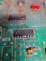
Thank you so much for your help with this.
I ordered the ULN2068B just in case.
Also I thought that under voltage regulator it was an old dry thermal paste, and reapplied a new one but like you said it was a thermal apoxy. Is that ok if I applied regular thermal paste that used for CPUs?
Another stupid thing I did is, I damaged spec information on axial electrolytic capacitor when I was trying to unstick it from that white gum. 🤯 How can I make sure that I order the right one to replace it? I have a picture befor damaging it, and I can see there's 25v but what else?
Do you think this is right one? https://www.elexp.com/products/14ea0251000ucap-elec-axial-025v-1000uf?variant=42638115340516
 

Attachments

  • 20240617_192148.jpg
    20240617_192148.jpg
    899.8 KB · Views: 39
Last edited:

ukateshka

Active member
Joined
Jun 12, 2024
Messages
29
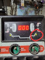
I tried to install weights where the arrows suggest to install, and whe next time I spin the wheel, the arrow shows in different spot. So in other words, I'm always chasing the spot if I add another weight. Is that normal in my case?
Also, the LED that wasn't working, it's alive again for some reason.
 

Attachments

  • 20240621_100014.jpg
    20240621_100014.jpg
    803.4 KB · Views: 41

gregs

Well-known member
Joined
Mar 16, 2007
Messages
1,603
That was the cap I asked about earlier. I think its used as a "filter" cap and if its bad can allow stray voltage to other areas and components that will cause wacky problems. You are going to have to try and separate the epoxy part off to read the value if you dont have a schematic or parts list for it. If it is indeed a filter cap, the value could be a little higher and it wont affect things. Basically if you can find another one close to it, you can swap it out to see if its the problem.
 

rlitman

Well-known member
Joined
Oct 18, 2010
Messages
24,650
Location
Long Island
I tried to install weights where the arrows suggest to install, and whe next time I spin the wheel, the arrow shows in different spot. So in other words, I'm always chasing the spot if I add another weight. Is that normal in my case?
Also, the LED that wasn't working, it's alive again for some reason.
Chasing the weights is a sign of miscalibration. Again, that means it is trying to balance, which means that the important parts inside there are doing their things (a VERY good sign).

I am with gregs. If the filter caps are failing, that could create enough noise on the DC side to make the brains unable to read the calibration memory. I think you might get the cap's value from a screen grab in one of your videos. Unfortunately I don't have the time to search that out right now.

Also, I found this today:

It seems that the Coats 6200HS is just about the same thing. The Coats had a rechargeable battery for cordless use, and I suspect that's what one of the unused connectors is for (the 4-pin molex).
 

ukateshka

Active member
Joined
Jun 12, 2024
Messages
29
Guys, finally I think it's working now. I installed the new darlington chip and here's the video.(you can hear a noise when the tire is spinning, it's a peace of tire valve inside the tire)

 
Last edited:
To avoid these ads, REGISTER NOW!
Top Bottom