
You are using an out of date browser. It may not display this or other websites correctly.
You should upgrade or use an alternative browser.
You should upgrade or use an alternative browser.
resistor identification - fixed, thanks to all that helped!
- Thread starter brooktre
- Start date
Cruzan80
Well-known member
Edited: don't do math tired, or you imagine more colors. 10 ohm, not 100.
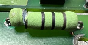
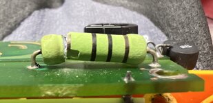
If it is Brown-Black-Black, it is a100ohm 10ohm resistor. The last band by the crack is the tolerance (looks gold to me)
Three blacks and a Brown doesn't make sense. Either it is using Brown for the tolerance (1%), but Black-black-black is a meaningless color combination (00x10^0), or it is100ohms 10ohms, but black doesn't denote a tolerance spec.
Most modern resistors are 5 band, not 4 band. Sure you aren't missing a color?
Can you find a schematic?
If it is Brown-Black-Black, it is a
Three blacks and a Brown doesn't make sense. Either it is using Brown for the tolerance (1%), but Black-black-black is a meaningless color combination (00x10^0), or it is
Most modern resistors are 5 band, not 4 band. Sure you aren't missing a color?
Can you find a schematic?
Last edited:
wyliesdiesels
Well-known member
wow did you blow up the T5-1000?
BillK
Well-known member
The second picture looks like Brown-Black-Black-Gold but its hard to tell for certain. I also see what looks like a paint "dot" on the left hand side in the first picture ? Are you sure it is a resistor ? I have seen some strangely marked diodes in some automotive applications.
I would call Fluke and see if maybe they will tell you or at least maybe send you a schematic ?
I would call Fluke and see if maybe they will tell you or at least maybe send you a schematic ?
tvand13
Well-known member
That isn't how the third multiplier band works(Check your math on 10^0). Brown black black is 10ohm. I agree that the last band looks gold. OP, can you confirm this?If it is Brown-Black-Black, it is a 100ohm resistor. The last band by the crack is the tolerance (looks gold to me)
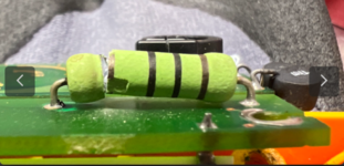
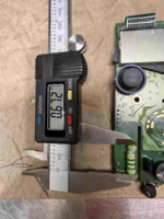
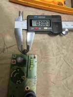
Also, it's definitely a resistor. Could you measure the body length and diameter so we can recommend a replacement? How was it damaged, and are there any other burned spots or components on the board?
jbltwin1
Well-known member
Looks like metal oxide from here but any 100 ohm will work for diagnosis. I would say about a 1/2 watt to 1 watt from the pic but the size can be misleading on a pic.
bwringer
Well-known member
I thought Flukes never ever failed, and you're gonna die of electrons in the pancreas if you use anything but a Fluke to check a flashlight battery... 
ratflinger
Well-known member
Bad Beer Rots Our Young Guts But Vodka Goes Well
They cleaned that one up since I went through Basic electronics back in the 80s.Bad Beer Rots Our Young Guts But Vodka Goes Well
Cruzan80
Well-known member
Yes, my bad. Too used to working with 5-band resistors with my students (doing an Arduino unit right now). Mentally went Brown-Black-Black-Black, which would be 100ohms (1-0-0-10^1).That isn't how the third multiplier band works(Check your math on 10^0). Brown black black is 10ohm. I agree that the last band looks gold. OP, can you confirm this?
Also, it's definitely a resistor. Could you measure the body length and diameter so we can recommend a replacement? How was it damaged, and are there any other burned spots or components on the board?
tvand13
Well-known member
I don't want to get this thread hung up on it, but even in that example 5 band, the black multiplier band is 10^0 = 1, not 10^1. Agree that brown black black black is 100ohms though.Yes, my bad. Too used to working with 5-band resistors with my students (doing an Arduino unit right now). Mentally went Brown-Black-Black-Black, which would be 100ohms (1-0-0-10^1).
OP, as soon as you can confirm that last band is gold and the physical dimensions, finding a new resistor is very easy. It's 10ohm, probably 5%, looks to be around 1 watt, but it's hard to tell the true size without a physical measurement.
Cruzan80
Well-known member
Yes, again. Ignore most of my math!
purplezr2
Well-known member

Chart for reference


MBfreak
MEMBER EMERITUS
Fluke schematic and/or access to an undamaged Fluke of same kind will solve your Q.
I guess 10 Ohms is correct and it does not look like it has been fried.
What I do not understand AT ALL is why the part is broken.
If it is part of a current circuit, FLUKE always use fuses to protect the shunts.
Never seen a blown FLUKE current circuit resistor.
Ola
I guess 10 Ohms is correct and it does not look like it has been fried.
What I do not understand AT ALL is why the part is broken.
If it is part of a current circuit, FLUKE always use fuses to protect the shunts.
Never seen a blown FLUKE current circuit resistor.
Ola
Worsedog
Well-known member
That looks to be a MOV. Metal Oxide Varistor. Used for surge and transient protection. If it's smoke damaged from its own construction, not transfer from another component, it likely gave its life and should also be replaced.
senlow
Well-known member
You missed the tolerancing. The mnemonic that I learned is:Bad Beer Rots Our Young Guts But Vodka Goes Well
Bad Boys **** Our Young Girls, But Violet Gives Willingly. Get Some Now.
rlwhitetr3b
Well-known member
While I learned the bad boy version in college, when I was teaching high school electronics we used bad boys race our young girls but Violet generally wins. I do not remember the tolerance part on either of them.
DGersic
Well-known member
Black-black-black is a meaningless color combination (00x10^0)
Not completely meaningless. I’ve seen 0 Ohm “jumpers” with a resistor body, because those are machine stuffable parts instead of having to hand stuff a jumper wire on a board being manufactured.
I can’t recall offhand if that was three black lines or one, though.
txvwnut
Well-known member
That is what I taught in high school tech class, after dad taught me the college version.While I learned the bad boy version in college, when I was teaching high school electronics we used bad boys race our young girls but Violet generally wins. I do not remember the tolerance part on either of them.
Cruzan80
Well-known member
Just so I make sure I am understanding correctly, by using a 0-ohm "resistor", the robot was able to grab it easier to solder/wire into place? I would think that it could be handled with better design of the PCB (I haven't designed those personally, so could be way off base).Not completely meaningless. I’ve seen 0 Ohm “jumpers” with a resistor body, because those are machine stuffable parts instead of having to hand stuff a jumper wire on a board being manufactured.
I can’t recall offhand if that was three black lines or one, though.
Or are you referring to some kind of retrofit?
DGersic
Well-known member
Just so I make sure I am understanding correctly, by using a 0-ohm "resistor", the robot was able to grab it easier to solder/wire into place? I would think that it could be handled with better design of the PCB (I haven't designed those personally, so could be way off base).
Or are you referring to some kind of retrofit?
Correct, a robot stuffed board. The robot is already stuffing resistors, so a 0 Ohm resistor is easy to spec instead of having to have it deal with a wire jumper.
Sometimes you can’t avoid a crossing. Sometimes it’s cheaper to use a single sided board and jumpers instead of a two sided board. Sometimes jumpers are provided for options that may need to be changed after it leaves the factory.
isb cornbinder
Well-known member
I called Fluke for a model 75 part and they sent it for free.The second picture looks like Brown-Black-Black-Gold but its hard to tell for certain. I also see what looks like a paint "dot" on the left hand side in the first picture ? Are you sure it is a resistor ? I have seen some strangely marked diodes in some automotive applications.
I would call Fluke and see if maybe they will tell you or at least maybe send you a schematic ?
Attachments

on an electronic repair site I watch on you tube ,according to him, 0 ohm resistors are used as fuses as well
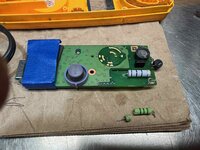
great on the repair