To avoid these ads, REGISTER NOW!

Above 1200 Sq/FT The Action Sports Garage

Wokspaces above 1200 squarefeet.
OP
G

Grant Gunderson

Well-known member
Joined
May 17, 2013
Messages
2,330
Location
Bellingham, WA
So with all your ski setup templates etc. would you recommend mounting your own bindings or having a shop do it? Its not something I anticipate having to do that often?

I just got another 2 pairs of skis, 90mm & 112 underfoot that need bindings mounted.

I see you use inserts.... i really like that concept but wonder if they are something a shop is going to charge me an arm and a leg for.
Unless you have the proper step drills and the jigs for your bindings I'd take them to a shop. I mount a ton of skis every year for the catalog shoots I do, so I have full setup of all of the factory jigs.

That being said, you can order the proper drills here. Most adult skis use a 3.6 x 9.5 drill unless they have metal in the top sheets, then you need a 4.1 x 9.5 drill plus the proper tap.

If you google your binding, you can probably find a paper template online for the hole pattern. The main things to keep in mind is making sure the hole pattern is centered on the ski, and that its in the correct spot for the Boot Center and your Boot sole Length.
 
To avoid these ads, REGISTER NOW!

trojandj

Well-known member
Joined
Nov 6, 2011
Messages
45
You can go a long way with paper templates, the right drill bits and a drill press. It takes a lot of time though. Inserts are awesome, but they get expensive fast. Even if you put them in yourself.

Also something to consider if a shop mounts the bindings you know the DIN settings and forward pressure, etc will be right. If you DIY you need to understand those as well.

It’s not rocket science but it’s also not drilling a couple holes.
 
OP
G

Grant Gunderson

Well-known member
Joined
May 17, 2013
Messages
2,330
Location
Bellingham, WA
The replacement foot stud for the Vorspung coil in my Zen fork arrived today.
IMG_2913.jpeg
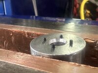
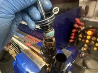
First step is to remove the broken foto shed. The shaft has a grove into it accept a 22mm cone wrench. A 15mm low-torque fits the foot stud nicely.
IMG_2915.jpeg
with the stud removed, you can see the porting for the hydraulic bottom out that the Vorsprung uses. The compression valve shims are visible on the old foot stud to the right. This is what separates Vorsprung from the Push AC3 coil conversion. With the Push, it uses an Air chamber for the bottom out, so it actually gets progressively stiffer as you bottom out. Vorsprung uses a hydraulic dampener for the bottom out, so it dissipates the energy when you bottom out.... this is way better. I own the Push AC3 on my trail bike and the Vorsprung on the E-bike and will only buy the Vorsprung when I replace the trail bike fork.
IMG_2916.jpeg
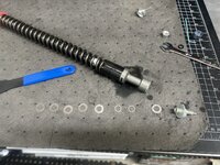
Here is the bottom out compression valve shim stack all laid out.
IMG_2917.jpeg
The new foot stud gets installed and torqued to 75inlb using a 15mm Crowfoot.
IMG_2956.jpeg
With the e-bike back operational, I took Stian out for a few laps on Galbraith. My plan was to tow him up most of the stuff, but he insisted on climbing it all himself. The new bike is making a big difference in his riding... so I am stoked.
IMG_2969.jpeg
As is he. Man I sure wish I had a bike this nice when I was his age.... but they didnt exist! Hell I didnt have a bike that nice 15 years ago!
IMG_2974.jpeg
We have some pretty talented trail builders around Bellingham these days too. Check out these trail side wood carvings!
IMG_2972.jpeg
IMG_2985.jpeg
Stian was having a lot of shifting problems. When we got home we put the bike in the stand and took a look at it. The NX deraileur had a ton of play in the pivot. So we swapped it out with a new one. He was actually pretty excited to do the work himself.
IMG_3021.jpeg
Finished the day with some smoked lamb and veggies.
 
Last edited:
OP
G

Grant Gunderson

Well-known member
Joined
May 17, 2013
Messages
2,330
Location
Bellingham, WA
My lady friend's bike needed a new drive train.
IMG_3041.jpeg
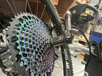
So I put a XX1 10-52 cassette on for her. I really like the Abbey crombie socket. Its really versatile for not just torquing on the cassette properly, but gets used a ton for suspension work, and even on some pedals.
IMG_3042.jpeg
Shes runnign a new 30T direct mount chain ring. I coat the interface and the threads with Ted-gel, then like to snug these down using a PBSwiss T25
IMG_3044.jpeg
They then get torqued with a T25 Nerpos socket. The Nepros are really high-quality, but not quite as good of a fit as my PBswiss sockets, but PBSwiss doesn't make a ¼ drive T25.
IMG_3045.jpeg
I rebuilt her XTR pedals, added fresh grease to the BB spindle, and then installed the cranks. The 8mm PBSwiss driver makes the install quick.
IMG_3046.jpeg
I then torque it down with an 8mm PBSwiss socket.
IMG_3049.jpeg
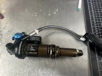
Just need to rebuild her shock, but waiting for a new Fox Factory needle injector tool to arrive for that.
 
OP
G

Grant Gunderson

Well-known member
Joined
May 17, 2013
Messages
2,330
Location
Bellingham, WA
You can go a long way with paper templates, the right drill bits and a drill press. It takes a lot of time though. Inserts are awesome, but they get expensive fast. Even if you put them in yourself.

Also something to consider if a shop mounts the bindings you know the DIN settings and forward pressure, etc will be right. If you DIY you need to understand those as well.

It’s not rocket science but it’s also not drilling a couple holes.
Setting the din is pretty easy compared to mounting the bindings...
IMG_9865.jpeg
To be honest, the DIN chart is really just a reference. it works for the average person, and is a good, conservative guide line. It's what I set my son and my lady friends bindings according too. However, those settings would never hold me or the athletes I work with in, and all of us tend to run a setting that is much higher than the chart states. For each ability level above 1, you go down the chart vertically by one space. IE intermediate ski, drops down the chart 1 space, an expert 2. I used to ski at a din of 18! Now with older knees, and modern more elastic bindings, I tend to ski with a din between 10~12 depending on the bindings.

Whats really important tho is making sure the forward pressure is set correctly,
IMG_9862.jpeg

and the toe height is correct.
IMG_9864.jpeg

If you dont have a toe height card, folding over a sheet of paper and placing it under the boot sole works. When set properly you should be able to pull the paper out, without tearing it.
 
OP
G

Grant Gunderson

Well-known member
Joined
May 17, 2013
Messages
2,330
Location
Bellingham, WA
The Lady friend's X2 shock was fully stuck down.
IMG_3081.jpeg
unlike most shocks, you cant fully service the air can on these without doing a full bleed of the damper, so you my as well tear it fully down. first step is to remove the Schrader valve core.
IMG_3082.jpeg
The Low speed compression and Rebound settings get back off fully CCW and I write down the # of clicks to get to full CCW so I can reset her settings latter.
IMG_3087.jpeg
Most fox shocks use a rubber pellet and needle system to charge the IFP in the resivor. The X2 uses a standard valve core, but you need an adapter to fit it. This old Rock Shocks one Ive had for years just happens to fit. It's supposed to be set to 100 psi, she only had 40 in it. I then bleed the rest of the air off.
IMG_3088.jpeg
I use a brass pick to remove the lock ring from the outer air can.
IMG_3089.jpeg
I can then slide the air can off. She is running one internal air can spacer (in orange). Since it's stuck down. I.E. vacuum in the inner air can, I need to be sure I remove any residual pressure in the oil circuit.
IMG_3093.jpeg
I remove the fill port, and get a bunch of foamy oil shooting out... clear sign a seal had failed.
IMG_3094.jpeg
The outer cap for the revisor then gets pressed in with my thumb, so I can remove the lock ring that holds it in.
IMG_3095.jpeg
I can then pull the cap out.
IMG_3096.jpeg
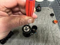
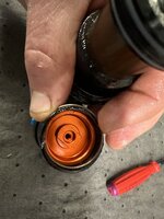
This reveals the Orange IFP, and its black bleed screw, which then gets removed.
Instead of unscrewing the upper seal head from the inner air can, I need to remove the bottom end first since its stuck down.
IMG_3111.jpeg
I use a shaft clamp to hold the main piston, and then unscrew the lower eyelit housing with the rebound knob.
 
OP
G

Grant Gunderson

Well-known member
Joined
May 17, 2013
Messages
2,330
Location
Bellingham, WA
IMG_3112.jpeg
I then remove the screws from the locking plate, and remove it. I then use the special service tool to slowly crack open the lower seal head. I do this slowly so I can vent the pressure. I can then pull the inner air can off.
IMG_3115.jpeg
The inner air can gets clamped in it's FOX factory shaft clamp and I sue the dedicated fox tool to remove the upper seal head.
IMG_3117.jpeg
A strap wrench then removes the stanction.
IMG_3118.jpeg
leaving us with the inner tube.
IMG_3120.jpeg
Progress.
IMG_3121.jpeg
I then clamp the resivor in some soft jaws and use the Fox factory eyelit tool to unscrew it.
IMG_3125.jpeg
The low-speed adjusters then get removed.
IMG_3127.jpeg
IMG_3129.jpeg
I can then unscrew the main bearing.
IMG_3130.jpeg
The main valve is the disk with the blue band and all of the holes drilled in it. The valve shims are spread out. This is basically a check valve and the shim stack determine the flow rate through it. This is effectively the base tune for the compression and the rebound. The high speed rebound adjuster on the shock, simply operates a Butterfly valve that controls how many of the valve ports are open for fluid to pass through. The lockout switch (blue lever) also operates a butterfly valve that allows oil to flow into the resivor or not.
 
OP
G

Grant Gunderson

Well-known member
Joined
May 17, 2013
Messages
2,330
Location
Bellingham, WA
IMG_3135.jpeg
Thats a lot of parts! All of the new seals are on the left. All that damper service really is, is replacing o-rings. To "tune" a shock all you are doing is modifying the shim stack for the valves.
IMG_3136.jpeg
This is all of the tools I used in the tear down. To re-assmble I use a torque wrench and a bunch of crowfeet in addition to these tools.
IMG_3143.jpeg
Here you can see one of the shim stacks reinstalled back onto the main bearing.
IMG_3144.jpeg
the small inner shaft is the high speed rebound adjustment.
IMG_3145.jpeg
Its o-ring was one of 3 that had failed.
IMG_3149.jpeg
Both the inner and outer o-rings on the main seal head also failed. The new ones are white on the left. The old ones on the right had hardened and yellowed.
IMG_3152.jpeg
The mai seal had gets installed on to the main shaft, and then the main bearing assembly gets torqued down.
IMG_3155.jpeg
the mai noosing gets new o-rings installed and I put the compression lockout butterfly valve back into the resivor chamber.
IMG_3156.jpeg
The resivor gets screwed back on, and the inner tube gets pressed back in.
IMG_3157.jpeg
and the stanction gets screwed back on.
 
OP
G

Grant Gunderson

Well-known member
Joined
May 17, 2013
Messages
2,330
Location
Bellingham, WA
IMG_3160.jpeg
the upper seal head for the inner air can goes on next. Along with the large inner volume spacer she is running.
IMG_3161.jpeg
If you are hand bleeding the shock, you would then fill the resivor with oil and insert the IFP next, then add more oil and insert the main bearing. I am going to vacuumed bleed it, so the main bearing assembly goes in next. As always, all seals get a coating of slickoluem.
IMG_3165.jpeg
It gets torqued on with the factory tool and a Crowfoot.
IMG_3166.jpeg
The lock plate then gets secured.
IMG_3168.jpeg
The IFP then gets installed along with the locking ring, so it doesn't get shot out when bleeding. Notice the bleed screw is removed. If you where to hand bleed it, now is when you would cycle the main shaft of the shock as many times as needed to get all of the oil to exit through that bleed hole. Since we are vacuum bleeding it, I install the bleed screw next.
IMG_3180.jpeg
Here is my home made bleeding adapter.
IMG_3189.jpeg
I first vacuum the shock, while cycling it by hand,
IMG_3191.jpeg
then do a fill cycle with oil, and then repeat the process until no more air is visible in the lines. The damper is now done.
IMG_3194.jpeg
I then install the inner air can, using the factory shaft clamps and tool. The outer air can goes on next, and the shock gets filled with air. Its important on these to sit on the bike and compress and decompress it while filling to equalize both air chambers.
IMG_3173.jpeg
Time to go test it out on some new trails!
 
OP
G

Grant Gunderson

Well-known member
Joined
May 17, 2013
Messages
2,330
Location
Bellingham, WA
IMG_3205.jpeg
What happens when you leave your shop for some time unoccupied with a Wilton 3C and an unprotected LS Starrett vise?
IMG_3207.jpeg
They some how reproduce like rabbits in the middle of the night, and you end up with a Reed 2C without any major damage to my wallet. I never thought I would have the need for more than 1 quality vise. Some how, I now have 3 very high-quality vises. Now that I am almost caught up with bike maintain and photo editing, I got a bunch of shop projects to start on. My goal for the summer is to finish the body work on the 10EE and get it powered up, restore both of these vises and the rotary table I picked up last summer. I'll be busy enough to stay out of trouble!
 

ebarker9

Well-known member
Joined
Oct 1, 2010
Messages
85
Really interesting to see the X2 rebuild. Obviously these shocks have a pretty terrible reputation for reliability and I also had a defective Float X from the factory, which is unfortunate because they do perform really well.
 
OP
G

Grant Gunderson

Well-known member
Joined
May 17, 2013
Messages
2,330
Location
Bellingham, WA
Really interesting to see the X2 rebuild. Obviously these shocks have a pretty terrible reputation for reliability and I also had a defective Float X from the factory, which is unfortunate because they do perform really well.
The problem with the X2 is there is just way too many seals in there and each seal is a potential failure point. I also absolutely hate how you cant due an inner air can service without having to do a full damper bleed. In my opinion they are trying way too hard to make an air shock feel like a coil. At the end of the day its just lipstick on a pig.

The only thing I like about the X2 is that it doesn't use the standard Fox pellet valve for charging the reservor / IFP spring.
 
OP
G

Grant Gunderson

Well-known member
Joined
May 17, 2013
Messages
2,330
Location
Bellingham, WA
up next is a Float DPX2 rebuild. This shock had a ton of cavitation going on. You could hear the oil and air mixing every time it compressed.
IMG_2796.jpeg
First thing I do is bleed the air off of the air can.
IMG_2799.jpeg
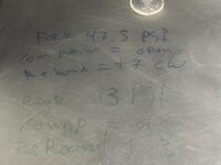
Anytime I am servicing suspension components, I like to first jot down the air pressure, and the settings it was being run at. In this case the shocked was at 113PSI, the compression was fully open, and the rebound was set at +3
IMG_2800.jpeg
I then remove the air pressure from the IFP. On most fox shocks, you need to remover the anti tamper pellet with a pick, then use a needle fill tool to remove the air pressure. These pellet valves are simmualr to those on a basket ball. I this case there was ZERO pressure in the IFP, so its seal clearly failed.
IMG_2802.jpeg
The hex plug that holds the pellet valve in can then be removed, along with the outer locking ring. Then a brass pick removes the retaining ring holding the IFP air seal.
IMG_2803.jpeg
The rear air seal, can then be pulled out.
IMG_2806.jpeg
The bleed screw can then be removed from the IFP.
IMG_2810.jpeg
look at how much foam is in that oil! Air was clearly mixing with the oil! Not what you want if you want the diaper / rebound systems to actually work.
IMG_2811.jpeg
With the air can removed, I place the lower eyelet in my vise soft jaws, then use a low-torque wrench to remove the main seal head. I can then drain all of the oil.
IMG_2812.jpeg
The compression knob is just held on by a small set screw.
IMG_2813.jpeg
I can then use a 17mm socket to remove the compression valve assembly.
 
OP
G

Grant Gunderson

Well-known member
Joined
May 17, 2013
Messages
2,330
Location
Bellingham, WA
The rebound knob just pulls off then it also gets removed.
IMG_2821.jpeg
The main piston shaft goes into my vise shaft clamps, and I remove the nut holding the main bearing assembly on.
IMG_2822.jpeg
The compression and rebound base valving is the shim stacks on either side of it. These can only be tuned by changing out their shims.
IMG_2827.jpeg
So here are the main components torn down.
IMG_2828.jpeg
The seals in the main seal head had gone bad. Notice how they have yellowed and become quite hard. With fresh seals and everything getting a thin coating of slickoleum it can all get put back together.
IMG_3396.jpeg
IMG_3398.jpeg
I torque the main seal head back down with a Crowfoot.
IMG_3399.jpeg
If you are going to hand bleed the shock, you would leave the bleed screw out of the IFP, however, I am going to switch to doing vacume bleeds for now on, so the bleed screw goes back in.
IMG_3400.jpeg
The IFP goes back in, along with the retaining ring.
IMG_3402.jpeg
We are now ready to vacume bleed. Here I have inserted my shop vacuum bleed adapter, since my Fox vacuum machine adapter in the rear doesn't fit this shock.
IMG_3403.jpeg
If you are going to do this, it's worth noting that on the Fox branded vacuum machine adapters, the use a ⅜ BSPT thread, this needs to get adapted to a ¼ MIP thread. That adapter is damn hard to find, I ended up sourcing it a hydraulic shop.
 
OP
G

Grant Gunderson

Well-known member
Joined
May 17, 2013
Messages
2,330
Location
Bellingham, WA
A proper vacuum bleeding machine is north of $3500... which is ridiculous for what they are.
IMG_3405.jpeg
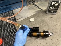
Here I am getting set up to bleed, first I put a filling hose adapter on, and **** in the 5WT fox oil into the accumulator chamber.
IMG_3408.jpeg
I can then attach the system to the shock via the adapter, and pull a vacuum on it. The shock compresses and the IFP gets sucked in. I then close the vacuum valve, and open the regulated air line into the system, to push the new fluid into the shock with 40PSI. I then repeat the vacume and pressure cycles 3~5 times until there is zero air left in the system. Its important to compresses and decompress the shock during this cycle as well as turn the compression and rebound valves, to ensure all air is out.
IMG_3409.jpeg
I then remove the bleed setup, and use my IFP setting tool to set the IFP at exactly 1.5"
IMG_3410.jpeg
The bleed adapter then gets removed. Notice how the fill port is completely full with oil.
IMG_3411.jpeg
the rubber seal puck gets dropped in/
IMG_3412.jpeg
and then the plug gets torqued down.
IMG_3413.jpeg
I then use a starter punch to tap in the new anti-tamper plug. The bleeding process is now complete.
IMG_3414.jpeg
The IFP gets a few drops of Float fluid to act as lube.
IMG_3415.jpeg
Then the air seal head gets installed along with the retaining ring.
IMG_3416.jpeg
and finally the lock ring.
 
OP
G

Grant Gunderson

Well-known member
Joined
May 17, 2013
Messages
2,330
Location
Bellingham, WA
IMG_3417.jpeg
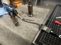
I decided to finally invest in the actual Fox fill needle set up. This thing is stupid exepensive. $100 for the needle, plus $55 for the hex adapter you need to open / close the seal. Finally another $6 for the schrader valve adapter. However it sure makes it easier, and its also a hell of a lot safer, as you defiantly do not want to accidentally inject compressed air into your skin.
IMG_3420.jpeg
shocks all back together and good to go!
 

RyanE

Well-known member
Joined
Feb 4, 2013
Messages
201
Location
Golden, BC
Grant - I just wanted to drop a note to thank you for the detailed bike suspension content. As a guy who dabbles in my own motorcycle suspension work and now getting into servicing my family's mtb suspensions, this has been a valuable resource!

Also PM me if you end up in Golden BC, my son is about the same age as yours and is always looking for new friends to ride with.

Cheers!
 
OP
G

Grant Gunderson

Well-known member
Joined
May 17, 2013
Messages
2,330
Location
Bellingham, WA
Grant - I just wanted to drop a note to thank you for the detailed bike suspension content. As a guy who dabbles in my own motorcycle suspension work and now getting into servicing my family's mtb suspensions, this has been a valuable resource!

Also PM me if you end up in Golden BC, my son is about the same age as yours and is always looking for new friends to ride with.

Cheers!
Glad it's been helpful. I'm usually only in Golden during the winer for work. However I may end up there this summer on a bike vacation... yet to be decided. Do you know Tess Treadway?
 

RyanE

Well-known member
Joined
Feb 4, 2013
Messages
201
Location
Golden, BC
I don't know Tessa personally but see her around town occasionally.

It's a small place, there's no anonymity!
 
To avoid these ads, REGISTER NOW!
OP
G

Grant Gunderson

Well-known member
Joined
May 17, 2013
Messages
2,330
Location
Bellingham, WA
…and one from the southern side of the world.

IMG_8308.jpeg
amazing. I've seen them a few times, but usually it’s just the greens. Evidently it has to be quite strong to get the reds and the purples. It was so strong here you could see all of the color with the naked eye as well.
I don't know Tessa personally but see her around town occasionally.

It's a small place, there's no anonymity!
I used to be quite good friends with her husband before his tragic accident. He and his brothers where some of my favorite athletes to work with.
 
OP
G

Grant Gunderson

Well-known member
Joined
May 17, 2013
Messages
2,330
Location
Bellingham, WA
Well against my better judgment I decided to go with the advice of my friends and finally offer suspension work to the general public. Made a single facebook market place ad for it and now I’m fully overwhelmed with work. I may have stumbled on to a new side business to my photography gig.

IMG_3522.jpegIMG_3497.jpegMy plan was to just test the waters and see if it would be worthwhile. I’m quickly learning the demand is out pacing my bandwidth.
 

McRae

Well-known member
Joined
Nov 18, 2009
Messages
114
Then you are in a great spot! Just need to learn how to say no... :)

Find your balance and book in jobs per that. If someone gets upset because you can't do it fast enough to suit their schedule, so be it, it's their loss, not yours... Also say no to stuff that you don't have the tooling/knowledge for, unless you are dying for the challenge.

Good luck with the side venture!
 

rbkool

Active member
Joined
Jul 9, 2015
Messages
33
Location
Calgary, Alberta
Time to raise prices until demand hits your capacity. 😀

Just make sure it doesn’t eat into your riding time.
These sentences are both exactly what I was going to say. You do great work; people will pay with a side benefit of raising prices is that it will keep out the "nickel and dimers" that you really don't want to deal with anyway... especially when it comes to something as finicky as shock work.

And don't give up fun/free time unless you want/have to!
 

zanyad

ALLIANCE MEMBER
Joined
Apr 26, 2018
Messages
2,817
Location
NE Ohio
Then you are in a great spot! Just need to learn how to say no... :)

Find your balance and book in jobs per that. If someone gets upset because you can't do it fast enough to suit their schedule, so be it, it's their loss, not yours... Also say no to stuff that you don't have the tooling/knowledge for, unless you are dying for the challenge.

Good luck with the side venture!

Time to raise prices until demand hits your capacity. 😀

Just make sure it doesn’t eat into your riding time.

These sentences are both exactly what I was going to say. You do great work; people will pay with a side benefit of raising prices is that it will keep out the "nickel and dimers" that you really don't want to deal with anyway... especially when it comes to something as finicky as shock work.

And don't give up fun/free time unless you want/have to!
:+1: to all the above.
 
OP
G

Grant Gunderson

Well-known member
Joined
May 17, 2013
Messages
2,330
Location
Bellingham, WA
This summer has been stupid busy with the new suspension business. I'm used to having my summers off, so it's been a bit of an adjustment to be so busy. It's good tho, the business is turning a profit, and is doing better than expected. However with all of the tooling I've had to purchase in two months it's only made what the photo business does in a good week. However now that I'm mostly set up and have purchased a large stock of the most common rebuild parts, it should start to show a pretty good return.

It's insane how many specialty tools modern bikes use. Just when I though I had everything, the suspension companies say hold my beer.

To accommodate all of it, I have decided to reconfigure a few drawers in the Vidmar and separate things out, Rock shocks / Fox in their own separate drawers.
IMG_0101.jpeg
Rock shocks drawer. I modified a Fox air spring removal tool to do the RS ones (drilled it out at tapped it for a M8 stainless piece of all thread). It's funny how just the Vivid, and Super Deluxe coil use 90% of the specialty tools. The rest are pretty basic. (other than the Brain shocks). Seems like they are starting to follow Fox's trend.
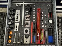
IMG_0118.jpeg
Fox is the king of specialty tools. I still dont have everything, but got what 99% of their stuff uses. I will say while their specialty tools are stupid expensive, they are very well made. I ended up getting some specialty tooling from another shop thats no longer doing suspension work and they had some non-fox made nock off tools and they just aren't as good. I'll be replacing those soon. I desperately need to find some higher drawer count under counter Lista cabinets so I can setup another drawer for Ohlins / Cane Creek, and then a 4th drawer for the outliers. Thats all thats currently holding me up for doing all of the brands.
IMG_0114.jpeg
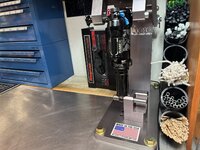
One of the shops in town called me up and let me know they are no longer doing suspension work (guess my business model of offering 24 hour turnarounds is working), so I bought a ton of tooling off of them for a fraction of the cost. Including this USA made, OSO Shock Dyno. Was going to order a new LAba7 unit with electronics from Europe, but they kept pushing the delivery date back. It was a blessing in disguise as this unit is better built. When I have time I will add my own electronics package to it.
IMG_0231.jpeg
I also machined a block of Delrin to keep all of my bleed fittings and bullet tools organized. Added a groove around the circumference to contain any oil that might drip off of them too. Sure is nice having them in a rack now, vs searching through a plastic tray for them.
IMG_4517.jpeg
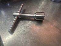
The 11.6 off my e-bike blew up on me. Only been 8 months since Push last serviced it. They did a **** job, and left some tooling marks on it, so I figured I'd do it my self. They dont publish a service manual, let alone specs, and dont sell parts, so I had to go about it 100% blind. Turns out it's dead simple. Essentially the same as a Fox DHX (even uses the DHX main seal). The only special sauce in it, is the massive shim stack they use, thats custom tuned to you and your bike. Configuring the shim stacks is a bit of a black art unless you have a very expensive universal testing machine and some data acquisition gear on the bike. In fact the Push only needed two specialty tools. One was an adjustable pin spanner that Facom makes for removing the main seal head. I then had to make a 4 pin spanner wrench for the pop it valves. The IFP just uses a basic needle valve to charge it.
IMG_4525.jpeg
IMG_4503.jpeg
Ive been learning a hell of a lot by servicing so many different shocks and forks. It's been nice to actually be turning a profit while essentially playing in the shop in my spare time. Only real issue is there is more demand than I have time, and I'm starting to get a lot of calls from guys asking me to do their Moto stuff and truck shocks.... I might go down that rabbit hole at some point, but I just dont have the room for the additional tools for those and quite frankly am too busy with the bike stuff as it is.
IMG_0163.jpeg
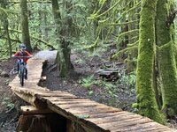
It hasn't been all work this summer tho. Lots of time on the bike. Especially with my son! The day after he got his cast off, we went to Whistler for the weekend and there was no holding him back. At 7 he's already riding all of the Blue trails there and starting to ride the blacks. Back home in Bellingham, he's riding everything on Galbraith and has really taken a liking to riding old school wood work. He was pretty excited about riding this Tettertotter thats taller than him! He rode into it blind, than proceeded to do it 3 more times! I have to say he's already better than dad when it comes to riding old school wood skinnies!
IMG_0179.jpeg
Now that he's riding some stuff thats big enough to have consequences, I invested in a bit more armor for him. Breaking his arm right before summer ended up being a good thing. He wasn't out that long (only 2 weeks), and it didn't curb his excitement to ride, but he no longer fights me about wearing safety gear. Life's good!
 
Last edited:

F-22

Well-known member
Joined
Jan 23, 2022
Messages
1,830
calls from guys asking me to do their Moto stuff
It was always hard to find a dependable mechanic, and I think that goes double for nowadays.

That said, it might be easier to do work on them for the most part. Performance bicycles are engineered more "on edge", with a smaller safety factor. A motorcycle will use one or two sizes larger fasteners in areas where same forces are necessary (smaller than M6 is only for bodywork).
 
OP
G

Grant Gunderson

Well-known member
Joined
May 17, 2013
Messages
2,330
Location
Bellingham, WA
It was always hard to find a dependable mechanic, and I think that goes double for nowadays.

That said, it might be easier to do work on them for the most part. Performance bicycles are engineered more "on edge", with a smaller safety factor. A motorcycle will use one or two sizes larger fasteners in areas where same forces are necessary (smaller than M6 is only for bodywork).
I’m confident they are easier to work on. The main issue is all of the specialty tooling is different and it means buying another entire set of bleed fittings, spring compressor etc. so it’s a pretty big investment in tooling. That being said from the number of people that have asked me it’s an even bigger market
 
OP
G

Grant Gunderson

Well-known member
Joined
May 17, 2013
Messages
2,330
Location
Bellingham, WA
IMG_0238.jpeg
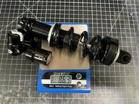
Just got the new Vorsprung. Pretty damn impressive on how good it is out of the box. It’s way more supple than the push I was running before. It’s also pretty cool that you can change the base valving without having to open it up to change a shim stack. You can even revalve it in the trail.
IMG_0236.jpeg
It’s lighter than the push too
IMG_0235.jpeg
Best way to describe it is that it feels like Moto suspension it just floats over everything and the hydraulic bottom out just ***** it all up. I’m impressed
 
OP
G

Grant Gunderson

Well-known member
Joined
May 17, 2013
Messages
2,330
Location
Bellingham, WA
Seems like such a cool product, particularly the externally adjustable base valve.
It's very interesting. There tuning support for it is pretty interesting too. You load the bike and rider info into their software and then it gives you a full tune for the shock that takes into account the rider, biker, terrain type, ability level, etc. Very similar to Push, but you dont have to send it in to have that done. Just to a shop with access to the software. Or the end user can tweak it themselves without the tune data too. I'm interested in taking it apart and seeing what they did to allow the external adjustment of the base valving. I have some ideas, but wont know for sure till I see the inside of it. They dont want me to do that until their patent is done. Thats understandable. It's also interesting that it uses a very small reservoir. It's surprisingly small compared to most higher end coils. Only thing Im not a fan of is they used a needle valve to charge the IFP instead of a Schrader or adapter for a Schrader. That makes it a bit more difficult for the DIY guys, but good for my service business I guess.
 
OP
G

Grant Gunderson

Well-known member
Joined
May 17, 2013
Messages
2,330
Location
Bellingham, WA
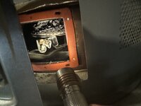
Last year I replaced all of the components on my furnace and realized all of the exhaust ducting for it was badly corroded so replaced it with the proper B venting that the house should have been built with. Fast forward to the last few months and my hot water heater pilot kept going out. So finally got around to tackling it. Figured it was a bad thermocouple. So picked one up and then took the cover off after it cooled off.
IMG_0781.jpeg
Well **** that doesn’t look good!
IMG_0782.jpeg
I can’t believe it would even work at all with that much ceap on the burner. Looks like a ton of rusted metal had ended up on it from the old vent piping I replaced last year. Never thought to check the burner from the hot water heater. Got it all vacuumed out and we will see if that fixes it!
 

ericm

Well-known member
Joined
Apr 17, 2016
Messages
1,963
Location
Southern Oregon
I'm interested in taking it apart and seeing what they did to allow the external adjustment of the base valving. I have some ideas, but wont know for sure till I see the inside of it. They dont want me to do that until their patent is done.
If they have filed the patent, it's ok to show the invention to people. Anything you did that infringed on the patent would be after the filing date and you could be found liable. In fact they could file a provisional, which is a lot less work than filing the full patent, in order to claim priority. I've done that a number of times when we wanted to show something to customers and hadn't gotten around to filing the patents yet.

I'm not a patent lawyer, just someone who has written a lot of patents. They should talk to a patent attorney about this.
 
OP
G

Grant Gunderson

Well-known member
Joined
May 17, 2013
Messages
2,330
Location
Bellingham, WA
If they have filed the patent, it's ok to show the invention to people. Anything you did that infringed on the patent would be after the filing date and you could be found liable. In fact they could file a provisional, which is a lot less work than filing the full patent, in order to claim priority. I've done that a number of times when we wanted to show something to customers and hadn't gotten around to filing the patents yet.

I'm not a patent lawyer, just someone who has written a lot of patents. They should talk to a patent attorney about this.
Since I’m set up as a dealer with them and they asked I didn’t open it up and share it I’m not going to. Don’t need to sour a relationship needlessly. But I am curious exactly what’s going on in there as all of the dampening is in the bridge and it has a solid piston unlike any other shock on the market. I’m betting they are using some sort of worm to adjust a valve orifice of some sort.
 

ericm

Well-known member
Joined
Apr 17, 2016
Messages
1,963
Location
Southern Oregon
Since I’m set up as a dealer with them and they asked I didn’t open it up and share it I’m not going to. Don’t need to sour a relationship needlessly. But I am curious exactly what’s going on in there as all of the dampening is in the bridge and it has a solid piston unlike any other shock on the market. I’m betting they are using some sort of worm to adjust a valve orifice of some sort.
I wasn't suggesting that you open it up without their ok and certainly not to share it without permission. I was suggesting that they could protect themselves legally now instead of waiting til the patent is issued.

Of course the protection of a patent only goes as far as they're willing to pay lawyers, but they have that problem either way.
 
OP
G

Grant Gunderson

Well-known member
Joined
May 17, 2013
Messages
2,330
Location
Bellingham, WA
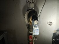
Ugh.. what is it with home owner projects that end up opening a can of worms. I checked my water pressure after fixing the hot water tank.... it was over 100PSI... gauge was maxed. OK WTF, the Expansion tank must be bad.
IMG_0783.jpeg
I'm pretty sure this guy was installed when they built the house 20 years ago. I checked its relief valve and only water came out... so it must be bad.
I replaced it with a new one.
IMG_0790.jpeg
And it still quickly reaches 75 PSI when the House Pressure Reduction valve is set to 50 PSI. I figure with the expansion tank I should see a bit of a pressure increase when the hot water heater is heating water, but 25 PSI seems excessive. I dunno but thats my assumption, maybe someone that knows more about this can clue me in.

I then turn off the water supply and drain the tank and all of the lines. I then set the pressure reduction valve to 40 PSI.
IMG_0797.jpeg
With the hot water heater off (and cold water in the tank), I then watch the static pressure climb to 70, then 80 PSI and it doesn't stop. WTF? I am guessing that confirms the main Pressure reduction valve is bad. I'm starting to think this explains why in the last 5 years, Ive had 3 major plumbing leaks... all of them where pin hole links in the middle of pipes or the sides of elbow joints in the hot water return line. Doesn't help that the crew that plumbed this house did a **** job... none of the solder joints look very professional.


Neither Lowes or Homedepot have a rebuild kit or non PEX valve instock. So ended up ordering a new one from Amazon... Hopefully it arrives tomorrow.

IMG_0796.jpeg

Since I got the water supply turned off to the house, I decided to install a pressure relief valve. I figure after 3 major water leaks in 5 years, it's cheap insurance at this point. It's factory set to 75PSI, so if the line pressure exceeds that it will dump water into the hot water tank emergency relief line that drains outside of the house. Ideally it will never need to operate if the main pressure reduction valve and the hot water expansion tank due their jobs.... or at least thats my assumption.
 
To avoid these ads, REGISTER NOW!
Top Bottom