To avoid these ads, REGISTER NOW!

VFD for my swivel head bandsaw- parameters ?

tarbellb

Well-known member
Joined
Apr 17, 2011
Messages
5,773
Location
Oregon
Looking for some advice on how to dial in this setup:


SEE UPDATE on post #5


Machine- Grizzly G0614 1.5hp swivel head metal band saw

VFD- Mysweety 2.2KWH unit 2.2KW 220V VFD: Input voltage: 220V(+/-15%); Output voltage: 220VAC; Input frequency: 50/60 Hz; Output frequency: 0-600 Hz; Input phase: 1 phase; Output phase: 3 phase


Good news I have it running and all seems fine? This is my first attempt at setting up a VFD and would like to confirm I have this running at optimal conditions.

The only parameters I have tweaked is the power input dial. I calculated Feet per Min to Blade rotations and have the blade spinning at roughly 170 FPM / 341 FPM w the power input at ~83%


Questions:

Q- Is the power input dial the ideal way to adjust the power going to the machine and setting the blade speed? If not, what is?

Q- Are there other parameters I need to be concerned about that would negatively effect the motor/electronics? The instructions are bit vague on checking things like frequency etc...

Thanks in advance ( I may post this separately if this thread doesnt get much traction)

Grizzly G0614 wiring diagram  components .jpg

Grizzly G0614 wiring diagram  control box.jpg

Mysweety VFD diagram.jpg

Mysweety VFD specs.jpg
 
Last edited:
To avoid these ads, REGISTER NOW!

Firebrick43

Well-known member
Joined
May 12, 2015
Messages
14,181
Location
West central Indiana
If the motor doesn’t have F class insulation I would advise not running it below 20hz in speed. You should be able to set a parameter/s to limit the hertz range.

There usually is a scaling parameter so the displayed speed can be SFPM if you want as long as there is no belt changes.

That is a nema 1 style case and is not ment to be exposed to the dust of a bandsaw. It should be mounted in an enclosure.

The face plate can be detached and used to control it with an extension. If you don’t mind the small buttons there is no reason to not use it. I prefer 30 mm AB momentarily switches and push buttons for ease but that is a preference.

I always recommend install at least one discrete E stop button. Trying to quickly shut off a machine via the small face plate is a disaster in the making.

You can reuse all the original controls and add a 10k pot next to them to control the speed as well
 

Ohmthis

Well-known member
Joined
Jan 20, 2013
Messages
3,019
Location
Outside of Louisville KY
It looks like the saw has controls. Use the start/stop and Estop wiring to control the saw. You need an Estop! It can be wired in to the digital inputs and programmed in. It will need to be an instantaneous stop. If it throws an over braking fault, who cares, the emergency is more important.
 
OP
T

tarbellb

Well-known member
Joined
Apr 17, 2011
Messages
5,773
Location
Oregon
Thanks for the replies

Yes I have the vfd running the saw controls as designed, it uses the on/off switch,2 pump switch, and speed switch (off, low, high)

Made a few cuts, things seem good!
 
OP
T

tarbellb

Well-known member
Joined
Apr 17, 2011
Messages
5,773
Location
Oregon
UPDATE:

Appreciate the feedback on how to approach the install. Multiple members have informed me its not typical to have switches between the VFD and motor.

However after reading the documentation for the this particular VFD it has several suggested wiring scenarios for the this type of install?
(Am I understanding this correctly???)

Can I get some feedback or advice on how I should be proceeding after looking at the attached pics?

Please advise, Thanks!

VFD doc 1.jpg

VFD doc 2.jpg
 
Last edited:

paulsomlo

Well-known member
Joined
Jul 16, 2013
Messages
3,907
Location
Northern Colorado
There are no surprises there - power in to the "N" and "L" terminals with the motor hardwired to "U", "V", and "W".

I believe you want 3 wire control, which means you need a momentary normally closed pushbutton for stop, and a momentary normally open pushbutton for start. It's very possible that you have everything you need right there on the Grizzly control panel - you've got two pushbuttons, an E-stop, some contactors, an overload device, terminal blocks, etc.. You just need to do some detective work and then rewire things. I guess I would start by confirming whether the two pushbuttons are NO or NC.
 

paulsomlo

Well-known member
Joined
Jul 16, 2013
Messages
3,907
Location
Northern Colorado
My interpretation, is that you would wire either U1, V1, W1 or U2, V2, W2 straight to the VFD output. I don't know the purpose of KM4 - can someone else chime in please? Is KM4 needed to short out U1, V1, W1 when using U2, V2, W2? Admittedly, I don't have a good grasp on pole switching arrangements for dual speed 3 phase motors.

It appears that your start and stop pushbuttons are the correct sense (NO and NC) - they would need to be rewired to the VFD control terminals, conceptually easy and probably logistically, as well. Your VFD should have a provision for the E-stop button.

It looks like you've got a contactor (fancy name for a relay) for the pump motor, two contactors associated with speed control, another contactor (KM4) that has me baffled, an electronic overload protection for the main motor, a fuse block for the pump motor. The rest consists of switches.

I hope this helps, rather than obscures - you'll probably want a multimeter, but that's about all you need, other than basic hand tools.
 

seber

Well-known member
Joined
May 31, 2016
Messages
4,205
Location
Deep East Tx.
It looks like the saw has controls. Use the start/stop and Estop wiring to control the saw. You need an Estop! It can be wired in to the digital inputs and programmed in. It will need to be an instantaneous stop. If it throws an over braking fault, who cares, the emergency is more important.
On every VFD that I have used, if you get an over braking fault the drive goes into free wheel. You need a braking resistor to make it work.
 

Ohmthis

Well-known member
Joined
Jan 20, 2013
Messages
3,019
Location
Outside of Louisville KY
On every VFD that I have used, if you get an over braking fault the drive goes into free wheel. You need a braking resistor to make it work.
Depending on the VFD and it’s ability to program, you can set an instantaneous stop with a fault. We also use an electro-mechanical brake for redundancy. I agree with the braking resistor though. Thanks for making me give a better explanation. I did not even open the (link) OP VFD, it may not even be able to do as I’ve suggested, that’s a “My Bad”!
 
OP
T

tarbellb

Well-known member
Joined
Apr 17, 2011
Messages
5,773
Location
Oregon
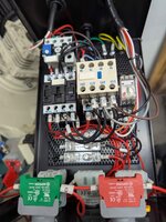
Pics of the saw control box, very well labeled. Im starting to figure out what needs to go where but any input to basic config and wiring is appreciated.


2 different angles


saw box 1.jpgsaw box 2.jpg
 
To avoid these ads, REGISTER NOW!

paulsomlo

Well-known member
Joined
Jul 16, 2013
Messages
3,907
Location
Northern Colorado
OK - I think I've got a handle on this.

You'll need to wire the red and green stop and start buttons on the saw to control the VFD as shown below from 6.2 on pg 9 of your VFD manual. SQ2 and SQ3, the E-stop and limit switch should be wired in series with the red stop button. I'm not sure if FR1 (overload relay) can be retained or not.

The wires U1, V1, and W1 directly from the motor should be wired directly to the VFD output. You should be able to disconnect them at the juncture of KM1 and KM4. This will provide the low speed setting, the VFD will do the rest, speed-wise. I think you can leave U2, V2, and W2 connected to the contacts at KM2, since KM2 won't be capable of energizing. You could remove these three wires from KM2 and tape them off, of course. The speed switch on the saw will not be functional.

To maintain functionality of the coolant pump, you'll need to provide it with power from L1 and L2. Although SB3 is referred to as "Pump Relay", I believe it's the pump switch, which should be a maintained spst rotary. You'll want to isolate SB3 and KM3 from the rest of the circuitry and feed L1 to the point on SB3 marked "3". Feed L2 to the bottom of KM3. The pump should run as normally expected from it's front panel switch.

The one thing you'll need to provide, that you don't have, is a disconnect switch for power to both the VFD and the saw's control panel, since they both need to be powered.

I'd welcome input from the other members here to ensure that I'm not giving out bad advice.

startstop.pnggrizzly.png
 

paulsomlo

Well-known member
Joined
Jul 16, 2013
Messages
3,907
Location
Northern Colorado
Looking at this again, with regards to the pump motor - the pump motor will need to be in parallel with the main motor, tied to the VFD output. Not ideal, but since the pump motor is 3 phase, I don't know how else to handle this. In fact, the only reason the saw's control panel would need L1 and L2 is to run the pump motor's control circuit.
 

paulsomlo

Well-known member
Joined
Jul 16, 2013
Messages
3,907
Location
Northern Colorado
On edit - I'm a little bit nervous about the pump motor control circuitry. It's set up to be powered by two phases of the 3 phase source. I'm not sure whether just L1 and L2 can be taken off the VFD's output, as that presents an imbalance. I had originally thought to take L1 and L2 off the incoming 240V, but you'll need to confirm that the KM3 contactor can handle 240VAC.
 

paulsomlo

Well-known member
Joined
Jul 16, 2013
Messages
3,907
Location
Northern Colorado
On page 8 of the saw's manual, there's another wiring diagram that might be useful.

There's a lot to digest here - an incremental approach might be best; maybe start by just rewiring the motor to run directly from the VFD, controlling the saw from the VFD's front panel. Then, try running the VFD from the start and stop buttons on the saw. Then, add in the E-stop and saw limit switches. Then, see about incorporating the coolant pump.

You may be able to do some of the connections using existing terminal blocks in the saw. I'm guessing that Grizzly used crimp ferrules for all the connections - you may need to cut some of those off. A handy way to make connections would be with Wago connectors.
 

paulsomlo

Well-known member
Joined
Jul 16, 2013
Messages
3,907
Location
Northern Colorado
I don't suppose there's a nameplate on the side of the motor? If so, and there's a wiring diagram, please post a picture of it.
 
OP
T

tarbellb

Well-known member
Joined
Apr 17, 2011
Messages
5,773
Location
Oregon
I don't suppose there's a nameplate on the side of the motor? If so, and there's a wiring diagram, please post a picture of it.

No name on the motor, no diagram either, just basic plate info. The wires have been labeled tho
 
OP
T

tarbellb

Well-known member
Joined
Apr 17, 2011
Messages
5,773
Location
Oregon
@paulsomlo wow thanks for the very informative support.

At this point I have the saw turning on through the panel OFF/ON switches and spinning (at what seems like the slower speed* ) on the VFD pot dial- see below

I ran the V1 U1 W1 wires directly from the motor to the appropriate terminals on the VFD
(I did need to change U with V on the terminals to change motor direction)

* I've removed the contact block that was providing the high speed function to clear up some space and give clarity?


Next step is to get the limit switch, then work on coolant pump.

🤙
 
Last edited:

paulsomlo

Well-known member
Joined
Jul 16, 2013
Messages
3,907
Location
Northern Colorado
@paulsomlo woke thanks for the very informative support.

At this point I have the saw turning on through the panel OFF/ON switches and spinning (at what seems like the slower speed* ) on the VFD pot dial- see below

I ran the V1 U1 W1 wires directly from the motor to the appropriate terminals on the VFD
(I did need to change U with V on the terminals to change motor direction)

* I've removed the contact block that was providing the high speed function to clear up some space and give clarity?


Next step is to get the limit switch, then work on coolant pump.

🤙
Success! Yes, the way you've got it wired will provide the lower speed range. If need be, it can be changed with a little effort.

The limit switch (and E-stop) can be wired in series with the red stop button.
 
OP
T

tarbellb

Well-known member
Joined
Apr 17, 2011
Messages
5,773
Location
Oregon
Success indeed @paulsomlo ! I have the ON/OFF buttons, Estop, and limit switch all working accordingly.

I've hit a wall with the coolant pump tho?

I'm not totally sure what I'm looking at and how to run just L1 and L2 to the pump.

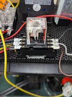
There is a fuse block and a 240v relay before the pump. How should approach this?
(relay and fuses all look to be intact)

Relay in question - Omron MY4N-GS AC 240v

saw relay 3.jpgsaw relay 2.jpg
 

paulsomlo

Well-known member
Joined
Jul 16, 2013
Messages
3,907
Location
Northern Colorado
I think it's OK to retain the fuses inline with the motor - if any of them blow, you still have the main motor loading the VFD. So, wire the upstream side of the fuses (should be the yellow wires) to the VFD output, essentially in parallel with the main motor. You can see this on the diagram in post #7. The only downside to this, is that the pump speed will vary if you vary the VFD. You will need to get the sense correct in order the get the pump to turn in the right direction.

Now, isolate the combination of the relay and SB3 (the pump switch). Connect the switch terminal that's electrically farthest from the relay to L1 (may be the red wire marked "3"). Now, I say L1, but a decision needs to be made - either L1 will be the output of the VFD or one of the 240VAC legs powering the VFD. You've had the entire saw running off the VFD early on - if the pump motor was working then, powering the relay coil off the VFD output may be OK. The relay coil is rated for 240V, so connecting L1 to the incoming 240VAC should be OK and that's pretty much a sure bet operation-wise, although logistically, it may be a bit more difficult to wire.

You'll need to id the relay coil terminal that's not wired to the pump switch (you can rule out L1,2,3 and U,V,W). That gets connected to your choice of L2, as per the above paragraph.

Do make sure that you isolate the relay and SB3 - you don't want them connected to anything they were connected to before (other than each other), as we don't want any of the contactors associated with the main motor energizing.
 
To avoid these ads, REGISTER NOW!
Top Bottom