To avoid these ads, REGISTER NOW!

240 V electrical

wyliesdiesels

Well-known member
Joined
Aug 14, 2012
Messages
20,192
Location
Modesto, CA
Sorry, Mike. That wasn't directed at you, but at the other person who keeps trying to drag obscure references into the thread. I figured yours was single phase, as +99.99% of 240V questions on here are Line/Line 1ph voltage, not L/N.

When I pointed out hydraulic (car) lifts aren't usually found in data centers, he posted a pic of a person/equipment lift, and I was checking if that (person) lift was the 240 Line/neutral he keeps insisting is relevant to this conversation.

I do "think" that something like what is pictured below is what Wylie was talking about for installing a 120V GFCI along with the 240V if you use 10/3. These appear to be "standalone" breakers or thermal cutoffs. So you could take one hot line and "branch" it to both the hydraulic lift and supply this, and the neutral would work for 120V. I am not a sparky by trade, so would probably want one of the others to confirm (also dont know if the GFCI would be ok with the "branching"). The two on the bottom have different sized options (15/20), and you would just not use/move the switch for the one on the top.

the 2 in the bottom of the pic are just small subpanels which was suggested by someone earlier in the thread
 
To avoid these ads, REGISTER NOW!

Cruzan80

Well-known member
Joined
Jul 22, 2015
Messages
4,436
Location
Denver, CO
the 2 in the bottom of the pic are just small subpanels which was suggested by someone earlier in the thread
Could you split off the feed into the small subpanel, and still travel to a machine?

Starting at a 30A breaker, and then in a junction box, have the 10/3 transition to two different paths (one taking black/red to lift, and black/white to a subpanel like these and then to a GFCI with the appropriate breaker)? Or would a small subpanel need at least three slots (2x for the 30A 240 line and one for the 15 or 20A GFCI)?
 

wyliesdiesels

Well-known member
Joined
Aug 14, 2012
Messages
20,192
Location
Modesto, CA
Could you split off the feed into the small subpanel, and still travel to a machine?

Starting at a 30A breaker, and then in a junction box, have the 10/3 transition to two different paths (one taking black/red to lift, and black/white to a subpanel like these and then to a GFCI with the appropriate breaker)? Or would a small subpanel need at least three slots (2x for the 30A 240 line and one for the 15 or 20A GFCI)?

junction box to lift and subpanel. then 15a or 20a breaker (could be GFCI breaker) and then 15a or 20a receptacle....
 

Cruzan80

Well-known member
Joined
Jul 22, 2015
Messages
4,436
Location
Denver, CO
I think you are saying that you can have a run from a "home" panel to a junction box, and then split and supply both the lift and a subpanel from one breaker/line in the "home" panel. If so, that is what I was asking (but was having a hard time phrasing above). If not, please correct me.

PS: Calling it "home" panel so nobody gets angry with the word "main", in case the garage is a subpanel (I know you can do a sub off a sub). Tried to think of a word that didn't have extra connotations attached.
 

mikedodge

Well-known member
Joined
Jun 27, 2017
Messages
2,918
Gees, seems like a lot of work just to get an outlet at the hoist. I'd stick with an extension cord. Or do the garagejournal way and put a new sub panel in if there's no spaces in the existing one. Then add multiple new outlets, don't forget a few for welders, and update the lighting while you're at it :)
 
OP
M

MikeC55

Well-known member
Joined
Nov 1, 2020
Messages
447
Location
CT
The walls and ceiling will be insulated, so I plan to run the 10-3 romex to a box directly above the power unit post (the motor/fluid reservoir mounts on the post). Then I'm thinking BX type armored cable from ceiling box to emergency disconnect switch. I know you shouldn't run romex inside conduit and I assume that's true for BX as well, so these will have to be individual insulated wires. Is there any reason I couldn't also run 12-2 romex in the ceiling box to be used for a 20 amp outlet (in the E disconnect switch box), connected to an independent 20 amp breaker? If I did this, is it ok to run the individual 120 V wires in the same BX as the 240 V lines?
And, Mike, I'm installing a new 24 breaker box, so will have plenty of room. I do plan to run a welder outlet and several 120 V wall outlets. For lighting, I like to put outlets in the ceiling for each shop light, so they can easily be changed/upgraded when required.
 
OP
M

MikeC55

Well-known member
Joined
Nov 1, 2020
Messages
447
Location
CT
I was thinking you could buy BX armor and run your own wires in it (like conduit). It doesn't appears it sells like that. I guess I could use conduit. It's a straight shot from ceiling to post. Just saw your post, Stuart. Thanks, that would be easier.
 

wyliesdiesels

Well-known member
Joined
Aug 14, 2012
Messages
20,192
Location
Modesto, CA
I was thinking you could buy BX armor and run your own wires in it (like conduit). It doesn't appears it sells like that. I guess I could use conduit. It's a straight shot from ceiling to post. Just saw your post, Stuart. Thanks, that would be easier.

you are confusing MC and AC (BX isnt made anymore) with FMC. MC and AC already have the conductors. FMC is just flexible metal conduit without any conductors in it. Buy FMC if you want to run individual conductors in a flexible metal raceway.
 

JohnX14

Well-known member
Joined
Jun 2, 2014
Messages
656
Location
Boston 'burbs
Also, you will likely want to make sure the FMC is at least 1/2" trade size. (I will admit to using 3/8" for the last 40 years in applications that were 'prohibited" per NEC.)
 

BurtEggley

Well-known member
Joined
Oct 8, 2024
Messages
903
Mike - you have probably already figured it out. When the single phase lines come into the house, the two alternating current legs are essentially 180 degrees apart. Compared to the neutral wire, when one is positive 120V the other is negative 120V. This gives two legs that are 120V between each and the neutral wire. Between the two legs, since one is 120V positive at its peak, and the other 120V negative, so there is 240V difference between the two legs. A 240V device uses the difference between two legs, there is no neutral wire needed to do that. Some devices, like say an electric dryer or an electric range/stove, might also have a clock or timer built in. That clock, the electronics, and the timer etc,. are probably designed to use 120V. In that case the two legs come in which gives 240V between the two legs for the heating elements, and then a neutral and one leg are used for the electronics. Since there is very little load for that clock etc., there is no need to worry about unbalancing the two legs coming into the house.

In this country, we normally use a black wire for the hot wire, although sometimes red is used. White is used for the neutral. If white is used for one leg in a 240V circuit, normally the electrician will wrap a couple inches at the end of that white wire in red or black tape so someone else knows it is hot. Sometimes they will use paint or a sharpie, but using electricians' tape to color it is normal.

Any electrical device can short out. If this happens, sometimes the metal frame carrying the device can become energized with that leg that has shorted out. Someone touching that frame is standing on the ground, and they can get hurt badly from a shock between the shorted wire to the frame, and the ground they are standing on. As the years have gone by, there has been more and more of a push to ground everything to prevent people from being hurt. Wiring in the 1900's - 1950's might only have two wires - a hot and a neutral. Then a third wire, usually green was added to most appliances etc., as a ground. Appliances into the 1980's might only have three wires - two which are hot and a neutral for that timer or clock etc.. Because someone could still get shocked, a fourth wire was added - a ground. As such a late appliance might have two hot legs, a neutral for the clock, timer or electronics to get 120V, and a ground (green or copper). Sometimes when metal conduit is chosen to install a wiring run, the conduit acts as the ground.

The general rule in consumer electrical is that it rarely hurts to be overly cautious when installing something electrical. If the code allows multiple solutions, choosing the solution that is safest never hurts - except sometimes it costs more financially. When that happens, some people will just say use the cheapest approved solution. Others will say spend the extra couple bucks and do it to a higher standard. That becomes a personal choice.

Remember to put some black or red tape on the last few inches of that white wire you are using to carry a leg of the power to your 240V device so the next person who looks at it will know it is a hot wire and not a neutral.
 
OP
M

MikeC55

Well-known member
Joined
Nov 1, 2020
Messages
447
Location
CT
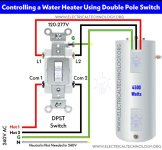
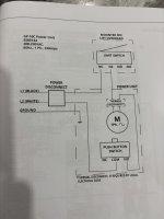
Thanks, guys. I think I'm going to run my 10-3 and 12-2 romex through the same 3/4 (straight conduit) to the power disconnect switch box. I have plenty of (sub) panel space, so running a separate 12-2 line to a 20 amp breaker in the panel seems easiest to me. I'll just cap off the white wire on the 10-3 as it's not used. The one thing I find a little confusing is wiring the double pole switch. I have a Leviton 30 amp DPST switch and it's not labeled as far as line/load. The attached diagram seems to spell things out clearly (not from Leviton), but it shows the brass screws on top and black screws on bottom. The Leviton, which is marked for 'top', has the black screws on top and brass on bottom. Is it universal that incoming power goes to brass terminals and load goes to black ones? Maybe it doesn't matter? The other thing I noticed today is the the wires going into the motor casing appear to only be 14 gage. Doesn't that seem strange? Is it the sign of a cheap motor?

A final question, would you recommend adding a thermal disconnect? The wiring diagram says "install thermal disconnect if required by local code" The wiring diagram suggests it needs 4 terminals, but the ones I'm finding only show 2 terminals...
 

Attachments

  • DPST switch.jpg
    DPST switch.jpg
    106.9 KB · Views: 25
  • IMG_1077.jpeg
    IMG_1077.jpeg
    487.6 KB · Views: 20
  • wiring.jpeg
    wiring.jpeg
    398.9 KB · Views: 24
Last edited:

Cruzan80

Well-known member
Joined
Jul 22, 2015
Messages
4,436
Location
Denver, CO
A final question, would you recommend adding a thermal disconnect? The wiring diagram says "install thermal disconnect if required by local code" The wiring diagram suggests it needs 4 terminals, but the ones I'm finding only show 2 terminals...
I would make sure to have one that has 4 total terminals (to break both hot lines). Otherwise, the ones with two terminals would only break one hot line.
 
OP
M

MikeC55

Well-known member
Joined
Nov 1, 2020
Messages
447
Location
CT
I haven't been able to find a single one rated for 30 amps with 4 terminals. I wonder if I could use a 2 terminal on each leg?
 

dave*99

Well-known member
Joined
May 5, 2009
Messages
4,324
Location
Coastal NJ
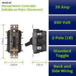
Leviton MS-302. Rated for 5 HP@240V

ETA: This would be used as the power disconnect, not thermal protection.

1786932506786.png
1786932587259.png
 
Last edited:
To avoid these ads, REGISTER NOW!

Cruzan80

Well-known member
Joined
Jul 22, 2015
Messages
4,436
Location
Denver, CO
Dave, I think Mike is saying that he can't find a thermal overload that is 2-pole.

I dont see a reason why 2x single poles wouldn't work, as it is the same idea as individual heaters in a magnetic starter. The only thing to be careful of would be to make sure you have to do something to "reset", otherwise it could start again unexpectedly if it cooled and the other line was still live.

Not having everything in front of me, I "think" a mag starter would work (and have thermal protection), but would have trouble instructing you on what wire terminates where remotely.
 

mm08822

Well-known member
Joined
Jan 13, 2012
Messages
6,225
Location
NJ
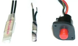
First check if the motor has a thermal overload built in to it. Typically, a red or black button barely sticking out of the motor housing. Probably find printing next to it to the effect of "press to reset". If the motor has it, then nothing else is needed.

If it doesn't, then provide a pic of the motor nameplate. You will then need to purchase a manual motor starter with thermal overload protection. Either you with need to purchase a thermal overload element (a.k.a. - heater) or it will have an adjustable dial inside to set the trip current value.

(The Leviton switch above does not have any overload protection.)
 

dave*99

Well-known member
Joined
May 5, 2009
Messages
4,324
Location
Coastal NJ
I did post a photo of the motor name plate in my previous post. It clearly says 'not thermally protected'. I found these, but would have to use 2 of them to protect both legs. https://www.amazon.com/Circuit-Brea...Protector/dp/B0DHVG1BFD/?tag=atomicindus08-20
The Amazon unit is a circuit breaker. I do not think it is actual thermal protection for the motor. Yes is says thermal circuit breaker, but it's a different use of the word thermal. Here it refers to how the breaker trips. Magnetic trip and thermal trip principles are used in breakers, but it is not equivalent to thermal protection for the motor.

At least that's what I get out of the ad, others may know more.
 
Last edited:

mm08822

Well-known member
Joined
Jan 13, 2012
Messages
6,225
Location
NJ
I did post a photo of the motor name plate in my previous post. It clearly says 'not thermally protected'. I found these, but would have to use 2 of them to protect both legs. https://www.amazon.com/Circuit-Brea...Protector/dp/B0DHVG1BFD/?tag=atomicindus08-20
I missed the nameplate pic when on my phone.

The overload protector you linked to on amazon is not sized for your motor. Nor is it a motor overload protector, it appears to be for a branch circuit. At 30a, it adds no value to the motor protection. There is also not mention of trip time or hp rating.

You need a manual motor starter with thermal overload protection rated for at least 3hp at 230vac.
The thermal overload element should be 125% of FLAs = 12a x1.25 = 15a. NEC 430.32(A)(1).

Only 1 thermal overload element is needed per NEC 430.37.

I can't find anything with a 3hp rating that is price friendly and with a simple mounting means.
 

djbmw

Well-known member
Joined
Jun 20, 2013
Messages
1,224
Location
Ottawa, Ontario, Canada
I did post a photo of the motor name plate in my previous post. It clearly says 'not thermally protected'. I found these, but would have to use 2 of them to protect both legs. https://www.amazon.com/Circuit-Brea...Protector/dp/B0DHVG1BFD/?tag=atomicindus08-20
If this is for a home shop and you're the only one using the lift.. just keep the motor under its rated duty cycle. Dont use it as an up&down amusement park ride, continuously on the button, and you'll be fine. If you DO overload it without a thermal fuse... its usually the motor capacitor that will blow... or a relay will fry... long before the wiring.

If you want to go the extra mile and install a thermal fuse... there's a few you can choose from. All of which require you to open the motor casing to affix the fuse close to the action.

-single phase (off winding, two or three terminals)
-automatic reset (attached to the stator coils or off winding)
-semi-automatic, or self-hold (attached to the stator coils , opens like an “auto” protector, but only closes once power to the motor was turned off)
-manual reset protector (mounted into front shield, motor housing)
 

Attachments

  • bodine_stator-wovlp_09-2009blog_white.jpg
    bodine_stator-wovlp_09-2009blog_white.jpg
    13.7 KB · Views: 9
OP
M

MikeC55

Well-known member
Joined
Nov 1, 2020
Messages
447
Location
CT
Yea, I'm the only one using the lift. I ain't gonna worry about it. Got it all hooked up and tested today. Works fine!
 

wyliesdiesels

Well-known member
Joined
Aug 14, 2012
Messages
20,192
Location
Modesto, CA
A final question, would you recommend adding a thermal disconnect? The wiring diagram says "install thermal disconnect if required by local code" The wiring diagram suggests it needs 4 terminals, but the ones I'm finding only show 2 terminals...

if the motor doesnt have integral overload protection you will need a motor starter.
 

wyliesdiesels

Well-known member
Joined
Aug 14, 2012
Messages
20,192
Location
Modesto, CA
If this is for a home shop and you're the only one using the lift.. just keep the motor under its rated duty cycle. Dont use it as an up&down amusement park ride, continuously on the button, and you'll be fine. If you DO overload it without a thermal fuse... its usually the motor capacitor that will blow... or a relay will fry... long before the wiring.

If you want to go the extra mile and install a thermal fuse... there's a few you can choose from. All of which require you to open the motor casing to affix the fuse close to the action.

-single phase (off winding, two or three terminals)
-automatic reset (attached to the stator coils or off winding)
-semi-automatic, or self-hold (attached to the stator coils , opens like an “auto” protector, but only closes once power to the motor was turned off)
-manual reset protector (mounted into front shield, motor housing)

this is horrible advice and a violation of the manufacturer's instructions which is also a code violation. a motor thermal overload will help protect the motor so it doesnt wear out prematurely....
 
Last edited:

djbmw

Well-known member
Joined
Jun 20, 2013
Messages
1,224
Location
Ottawa, Ontario, Canada
this is horrible advice and a violation of the manufacturer's instructions which is also a code violation. a motor thermal overload will help protect the motor so it doesnt were out prematurely....
I dont have the NEC on this computer (and I know OP is in Connecticut).. but I whipped up my PDF of the CEC (Canadian Electrical Code), as I'm in Canada.

Overheating protection is talked about in section 28-314 to 28-318. Specifically, overheating protection is not required if an overload protective device is already installed, as per Rule 28-302, and adequately protects the motor against excess current.

Rule 28-302 (Types of Overload Protection) talk about the types of overload protection devices. In relation to motors, the overload protection must be capable of protecting the circuit and motor under both overload and short-circuit conditions. A circuit breaker does just that.

So, at least in Canada, a circuit breaker is what's minimally required.

Now.. is a thermal fuse or PPTC a good idea? Yes, of course. And in a commercial environment that's likely to hit the duty cycle several times throughout the year, I wouldn't think twice about having one installed. Having said that, I have several 1HP to 5HP motors that aren't thermally protected (only overload/over current protected) that are Non-continuous duty service, operated manually.
 

mm08822

Well-known member
Joined
Jan 13, 2012
Messages
6,225
Location
NJ
A 30 amp cb does not overload protect a motor with fla=12a.

No way CEC permits that. Better re-read your 28-302 after you read the definition section.
 

djbmw

Well-known member
Joined
Jun 20, 2013
Messages
1,224
Location
Ottawa, Ontario, Canada
A 30 amp cb does not overload protect a motor with fla=12a.

No way CEC permits that. Better re-read your 28-302 after you read the definition section.
You're right - 30amp branch circuits are overkill and should not be used for overload protection.

Since SF is 1.15 then 12 FLA x 1.25 = 15 amp.

If the motor can run using 15 amp branch CB, and the inrush doesnt trip it, then it can also function for overload.
 
Last edited:
OP
M

MikeC55

Well-known member
Joined
Nov 1, 2020
Messages
447
Location
CT
I had no issue running my 10-3 and 12-2 romex in the 3/4 conduit. It was only a 5.5' length and straight. If there were any bends, I'm sure that would make things far more difficult. The lift instructions say to use a thermal disconnect if required by local code. I did search a bit to see if I could find anything pertaining to CT and all I found was specific to oil burner motors.
 

mm08822

Well-known member
Joined
Jan 13, 2012
Messages
6,225
Location
NJ
You're right - 30amp branch circuits are overkill and should not be used for overload protection.

Since SF is 1.15 then 12 FLA x 1.25 = 15 amp.

If the motor can run using 15 amp branch CB, and the inrush doesnt trip it, then it can also function for overload.
Still wrong. Read up on class 10, 20 and 30 motor overload devices.

You singlehandedly are trying to undo what the electrical industry has known for the better part of a century.

Using you example above, first off the 15a cb would trip on inrush.
Secondly at 15a during an overload, that 15a cb would not trip indefinitely. Check the cb time curve. As such, that motors insulation would overheat, breakdown and eventually short out and /or ground out.
And for good measure, thirdly, how many motors have you seen where fla's and/or sf amps match a standard cb rating?
 

mm08822

Well-known member
Joined
Jan 13, 2012
Messages
6,225
Location
NJ
I had no issue running my 10-3 and 12-2 romex in the 3/4 conduit. It was only a 5.5' length and straight. If there were any bends, I'm sure that would make things far more difficult. The lift instructions say to use a thermal disconnect if required by local code. I did search a bit to see if I could find anything pertaining to CT and all I found was specific to oil burner motors.
Read the NEC article 430 that I referenced above and a few before it.

I doubt CT has amended out the need for motor overload protection from the basic NFPA 70 (NEC) code standard that it adopted.
 

djbmw

Well-known member
Joined
Jun 20, 2013
Messages
1,224
Location
Ottawa, Ontario, Canada
Still wrong. Read up on class 10, 20 and 30 motor overload devices.

You singlehandedly are trying to undo what the electrical industry has known for the better part of a century.

Using you example above, first off the 15a cb would trip on inrush.
Secondly at 15a during an overload, that 15a cb would not trip indefinitely. Check the cb time curve. As such, that motors insulation would overheat, breakdown and eventually short out and /or ground out.
And for good measure, thirdly, how many motors have you seen where fla's and/or sf amps match a standard cb rating?
If it continually trips on inrush then there's no worry about burning up motor windings as the lift will never be in use anyway.

In all seriousness, I mentioned the different types of thermal protection he could use, along with yourself and Wiley.

Having said that, there are various codes around the world that allow for nuances - some specifying that motors dont need overload protection if they are manually operated while in use (generally for 1hp or less), and other regions making additional variances.

The motor's home is on a vehicle lift that is being manually operated with a momentary switch for typical durations of ~20 to 50 seconds once a week. It cannot be used unsupervised and is not continual duty.

If OP wants to keep everything 100% above board then the easiest thing would be to return the motor to the retailer and tell them to supply one with overload built in already.
 

mm08822

Well-known member
Joined
Jan 13, 2012
Messages
6,225
Location
NJ
If it continually trips on inrush then there's no worry about burning up motor windings as the lift will never be in use anyway. So that's a helpful solution.....seriously?

In all seriousness, I mentioned the different types of thermal protection he could use, along with yourself and Wiley. Yes, yours however would need to be evaluated for the correct values and placement within the motor. Modifying the motor housing isn't the way to go and voids any listing. The concept is fine, but there is no data to support that the motor would be safely protected w/o test data.

Having said that, there are various codes around the world that allow for nuances - some specifying that motors dont need overload protection if they are manually operated while in use (generally for 1hp or less), and other regions making additional variances. Well, OP has a 3HP motor and lives in Connecticut which is under NEC.........the rest is just fluff.

The motor's home is on a vehicle lift that is being manually operated with a momentary switch for typical durations of ~20 to 50 seconds once a week. It cannot be used unsupervised and is not continual duty. That's about the only thing saving it now. Assuming someone respects the duty cycle stated on the motor, which I'm sure is not promanantly dispalyed.

If OP wants to keep everything 100% above board then the easiest thing would be to return the motor to the retailer and tell them to supply one with overload built in already. Sure, probably to some back alley in China and he pays shipping. The mfr screwed the customer to save a few $. Never cheaper than motor mfr providing a tested OL for their motor.
SMH You should read up on the differences between overload protection and over current/short circuit protection in motor circuits.
 

mikedodge

Well-known member
Joined
Jun 27, 2017
Messages
2,918
In reality how often is a lift installed and anything more is done electrically then hooking up power to it, connecting the height limit switch if it has it and putting some sort of disconnect switch nearby? Looking up the number from the diagram the OP posted it looks like a typical hydraulic lift power unit.
 
To avoid these ads, REGISTER NOW!
Top Bottom