To avoid these ads, REGISTER NOW!

Convert 3.5" round workbox to outlet

OP
A

aragno

Active member
Joined
Oct 31, 2021
Messages
37
From this revised info:
1) You are saying Jacket #1 is not the other end of Jacket#4? (If it isn't the same, then there is another box unaccounted for.)
2) Draw in the cabling/connections for the floodlight. Show the floodlight and whatever cable it is connected to.
3) Need voltage test repeated with both switches (labeled) put in the chart and tested for each switch position.
1) I don't definitely know that Jacket #1 is not the other end of Jacket #4. It seems that way but I can't tell. I don't have a long enough set of cables for my multi-meter to check continuity from one end to the other.

2) I am unsure how the floodlight is completely wired in and I tried to only include what I know.

3) I've test both switches in all positions and combinations, and the black wire in the ceiling.
Updated graphic to reflect these tests but not for the above 1 and 2 since I don't yet have anything concrete. I'm happy to prove one way or the other and update so we are all on the same page.
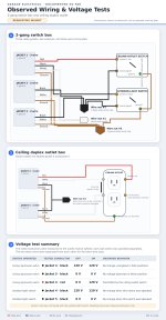

garage-wiring-findings-infographic-final (3).jpg


I’m thinking I misread post 26. It does look like power hits switch box first. So a GFCI there can work.
I suppose the downside to a GFCI breaker on this circuit is the circuit will be very sensitive to small milliamp fluctuations and may nuisance trip. is that correct?
 
To avoid these ads, REGISTER NOW!

mm08822

Well-known member
Joined
Jan 13, 2012
Messages
6,305
Location
NJ
Check if the black wire in jacket #1 goes to the floodlight switch or to wire nut #2.

Then disconnect the black wire of jacket #1 from the switch. Is the loose black wire from jacket#1 0v?

If it is 0v, do the voltage test again.
 

dscheidt

Well-known member
Joined
Apr 26, 2017
Messages
2,971
Yes
For example, I have heard that a refrigerator will sometimes trip them.
Any appliance that trips a gfci is defective. Fridges that are doing it are usually actively trying to kill you — the usual cause is the defrost heater is shorted to the chassis.

Nuisance tripping on gfci are really only a problem when there are long cables, or when there are lots of loads, each with very small leakage.

Some motor drives have problems, as you can read about in the recent VFD thread, but modern high quality gfci devices have better features for hf leaks. A breaker from the panel manufacturer should be good quality…
 
OP
A

aragno

Active member
Joined
Oct 31, 2021
Messages
37
Check if the black wire in jacket #1 goes to the floodlight switch or to wire nut #2.

Then disconnect the black wire of jacket #1 from the switch. Is the loose black wire from jacket#1 0v?

If it is 0v, do the voltage test again.
I've updated the drawing to accurately reflect black wires on Outdoor-light switch. I had them backwards.

I disconnected black from Jacket #1 and found:
I checked voltage with the power off and on.
With Power off, 0v on both black wires at the switch.
With power on, 0v on the black wire going to Jacket #1, and 120v on the black wire going to/from the pigtail (wire nut #2)

I also checked the 2 black wires in the ceiling outlet (with the wire removed from outdoor switch):
with power off, 0v on both black wires
with power on 0v on both wires until I turn "on" the switch for the ceiling and I get about 20v on black on Jacket #4.garage-wiring-findings-infographic-final (4).jpg
 

mm08822

Well-known member
Joined
Jan 13, 2012
Messages
6,305
Location
NJ
You need to get all of the the actual wiring between boxes figured out. Your reported voltage measurements don't match what the sketched wiring portrays.

The 2 suspended lights shown in pics appear to be inside living space but the discussion is about garage lighting with a single porcelain bulb holder. Why show them?

Plug cable 5 into an extension cord. Does the floodlight turn on?
 
OP
A

aragno

Active member
Joined
Oct 31, 2021
Messages
37
You need to get all of the the actual wiring between boxes figured out. Your reported voltage measurements don't match what the sketched wiring portrays.

The 2 suspended lights shown in pics appear to be inside living space but the discussion is about garage lighting with a single porcelain bulb holder. Why show them?

Plug cable 5 into an extension cord. Does the floodlight turn on?
The photos of the indoor suspended lights are from another commenter, not me :)

With respect to Jacket 5 (in the ceiling), should I take both the white and the black and attach to an extension cord/known power or just the black only and leave the white?
 
To avoid these ads, REGISTER NOW!

mm08822

Well-known member
Joined
Jan 13, 2012
Messages
6,305
Location
NJ
I applied power to Jacket #5 black and white from an extension cord on a separate circuit.
The outdoor light turns "on"
Not surprising. As expected. So re-label jacket 5 as going to flood light.

Hook everything back up in both boxes, do now both switches independently control ceiling lights and floodlight?
 

Higgins

Well-known member
Joined
Dec 25, 2009
Messages
1,956
Location
Shepheardsville, KY
They don't exist. a 3.5 box isn't big enough, a 4" is. As I noted earlier, most of the outlet covers available are not code compliant, as code now requires the receptacle to be held by two screws. There are listed assemblies of a cover and an outlet.
Flip it over and drill two holes. use appropriate hardware to secure socket to plate! Done!!
 
OP
A

aragno

Active member
Joined
Oct 31, 2021
Messages
37
Not surprising. As expected. So re-label jacket 5 as going to flood light.

Hook everything back up in both boxes, do now both switches independently control ceiling lights and floodlight?
Everything is now reconnected and switches work independently to control ceiling light and floodlight.

Let me know what we need to test (and how to do so) with the switches and I can do so.
As before, goal is to determine if/how I can add a dead-face GFCI near the ceiling-outlet switch :)

Updated drawing attached with the voltage test direct to the floodlight
garage-wiring-findings-infographic-final (8).jpg

Flip it over and drill two holes. use appropriate hardware to secure socket to plate! Done!!
I determined this box was 4," added a 1/2" spacer to give a little more room, and used a Leviton round plate/receptacle assembly I found at my local Ace Hardware.
 

mm08822

Well-known member
Joined
Jan 13, 2012
Messages
6,305
Location
NJ
The last 1/2 of post 30 tells you how to do it with either method of gfci protection.

Your voltage test summary has given me ADHD.........how are these answers possible if now everything works as it should...o_O
1788898528580.png
 
OP
A

aragno

Active member
Joined
Oct 31, 2021
Messages
37
The last 1/2 of post 30 tells you how to do it with either method of gfci protection.

Your voltage test summary has given me ADHD.........how are these answers possible if now everything works as it should...o_O
1788898528580.png
Does this make more sense? I revised the table a bit and I also re-tested.
I removed wire nut #2 and separated the black wires.

Jacket #4 had 0v with all switches off.
Jacket #4 had 120v when the floodlight switch was "on"
Jacket #5 always 0v (as expected since it goes to the floodlight it appears)
One oddity, when floodlight is off, and ceiling light is "on" the Jacket #4 black get 16v....

garage-wiring-findings-infographic-final (9).jpg
 
Last edited:
OP
A

aragno

Active member
Joined
Oct 31, 2021
Messages
37
The last 1/2 of post 30 tells you how to do it with either method of gfci protection.

With respect to the wiring, the CB is a fairly easy one, but I am struggling to figure out the wiring at my switches to put in the dead/blank face GFCI.
If you want to gfci protect the ceiling recept (and floodlight) from the 2g location with a gfci dead front or gfci recept, you have to install it upstream of wirenut #2. Both switch's power has to come from the load side of the gfci. The neutral for jacket #1 has to go onto the load side of the gfci.

Either bust out the 2g box and put in a 3g or change the 2 single pole switches to a tandem switch device to make room the gfci device.

Or just change the cb to gfci version and cover the entire circuit without changing anything in the 2g box..

I am a bit confused on how this will actually look at the end of the day and with which wires going where into wirenuts, jumpers, etc... this is the part I'm finding a bit confusing.

My plan was to install the blank/dead face GFCI below the existing 2g box. I could spend some time to dremel out the current 2g box and install a 3g old work box if that's realistic.

I'd prefer to keep minimal devices on the GFCI to reduce likelihood of nuisance trips from LED lights fitted in the other room fixtures on the same breaker.

I'll use the CB panel if I have to though.
 

mm08822

Well-known member
Joined
Jan 13, 2012
Messages
6,305
Location
NJ
With respect to the wiring, the CB is a fairly easy one, but I am struggling to figure out the wiring at my switches to put in the dead/blank face GFCI.


I am a bit confused on how this will actually look at the end of the day and with which wires going where into wirenuts, jumpers, etc... this is the part I'm finding a bit confusing.

My plan was to install the blank/dead face GFCI below the existing 2g box. I could spend some time to dremel out the current 2g box and install a 3g old work box if that's realistic.

I'd prefer to keep minimal devices on the GFCI to reduce likelihood of nuisance trips from LED lights fitted in the other room fixtures on the same breaker.

I'll use the CB panel if I have to though.
First start with is there enough room between the studs to fit a 3 gang box.
You could put a gfci recept in with the 2 switches instead of a deadfront.

A box below the 2 gang box could look a little hokey and then you have to run cables to it, possibly splicing within the 2g box. Box fill gets tight.

At this point, just put in the cb and see if the other stuff on the circuit plays well with it.
 
OP
A

aragno

Active member
Joined
Oct 31, 2021
Messages
37
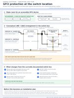
if i correctly understand the GFCI wiring, I would need:

- retain jacket 2 and 3 black wires in wire nut #2.
- add a black jumper from wire nut #2 to Line Hot side of GFCI

- retain jacket 2 and 3 white wires in wire nut #1
- add a white jumper from wire nut #1 to Line Neutral side of GFCI

- use a new wire nut (#5) to connect from Load Hot (new black wires) and in the same wire nut also have wires going to Hot on each switch
- attach Jacket 1 white wire to Load Neutral side of GFCI

- add additional ground jumper to wire nut #3 and connect to ground side of GFCI

this graphic might illustrate it correctly. It appears to be correct to me but I'm not an expert!
gfci-at-switches-concept.jpg
 
To avoid these ads, REGISTER NOW!
Top Bottom