michakaveli
Well-known member
That looks Great!


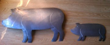
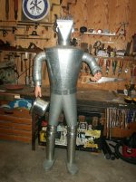
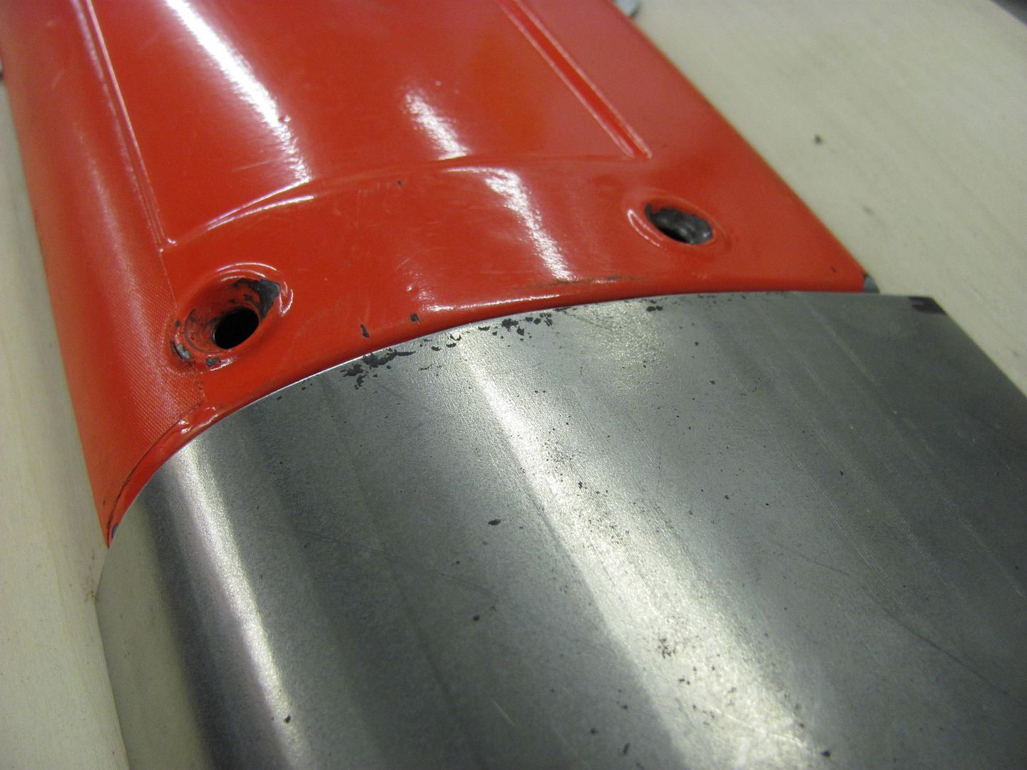
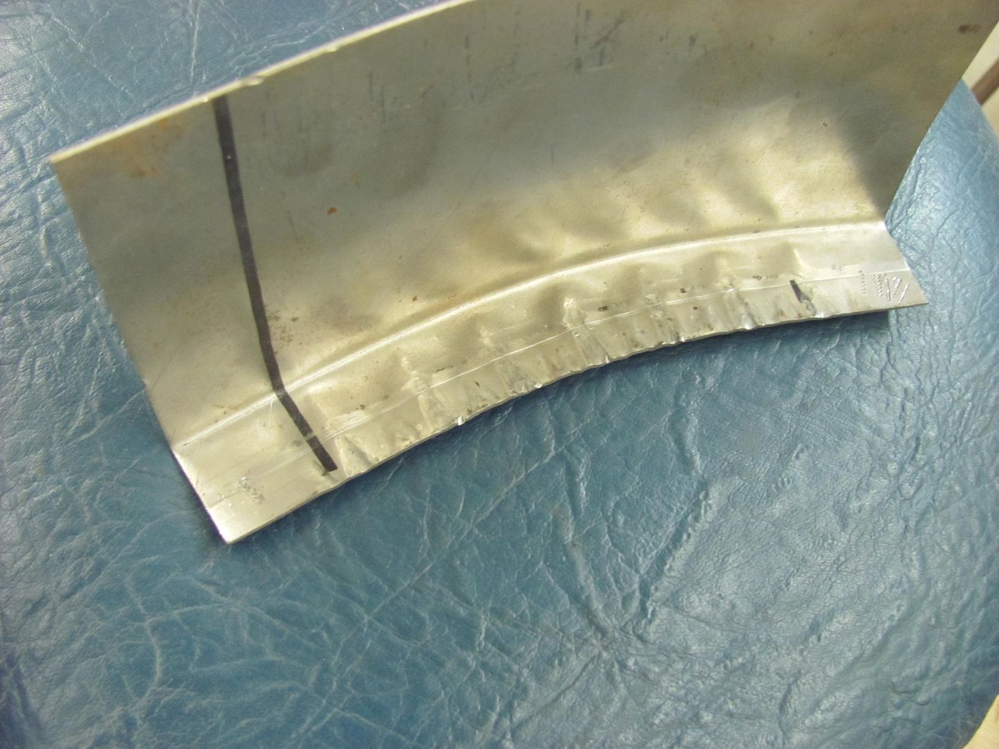
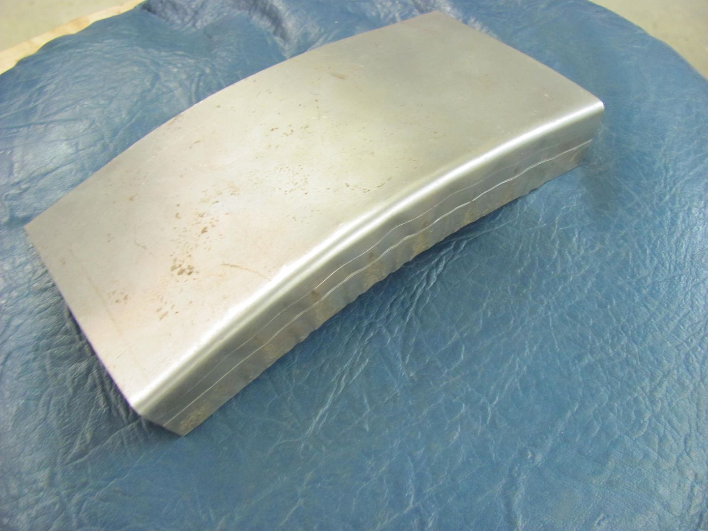
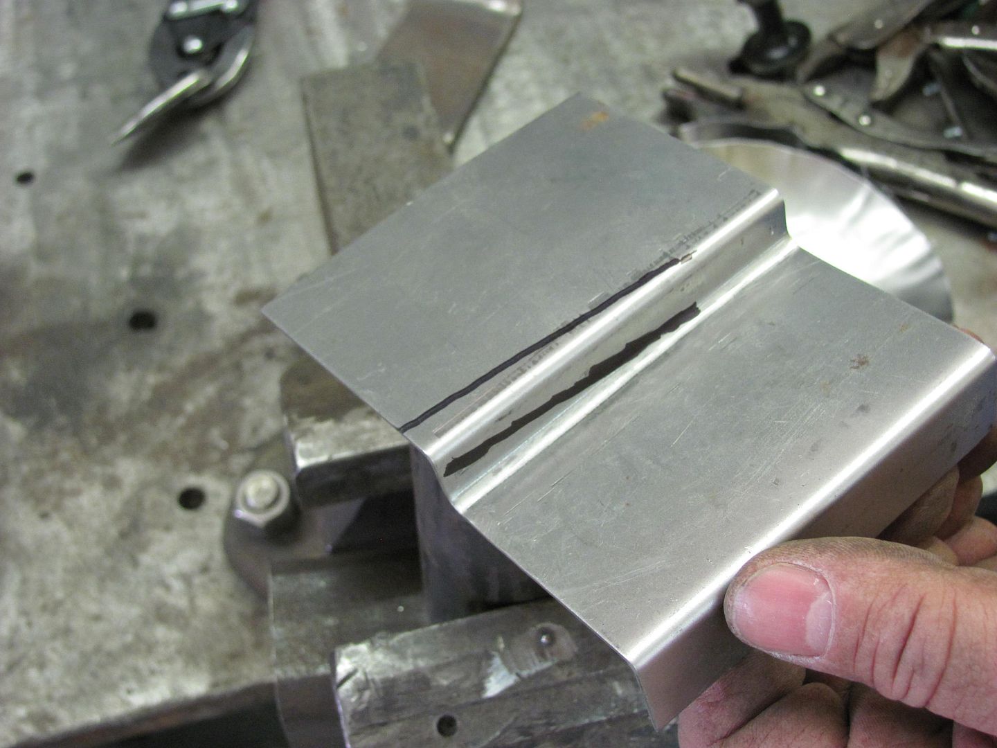
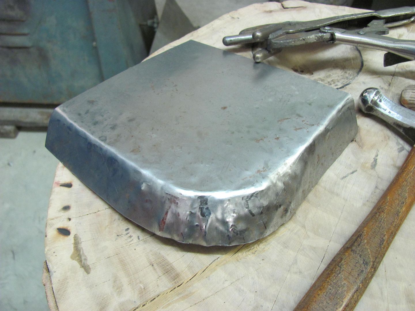
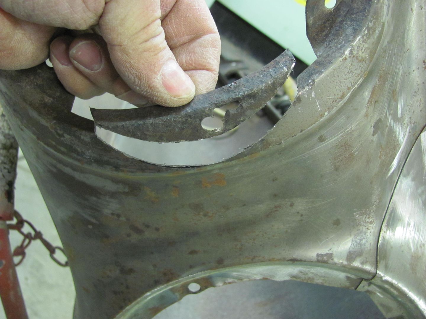
Here is a pig I made for my brother for his birthday. It is cut into its meat cuts. It mounts to the wall with a bracket that can be mounted to the wall and the pig hung on the bracket. It is about 30 inches long. I carved the letters for the stamps out of wood. The last pic is before it was cut up. I made a little one for the wife.
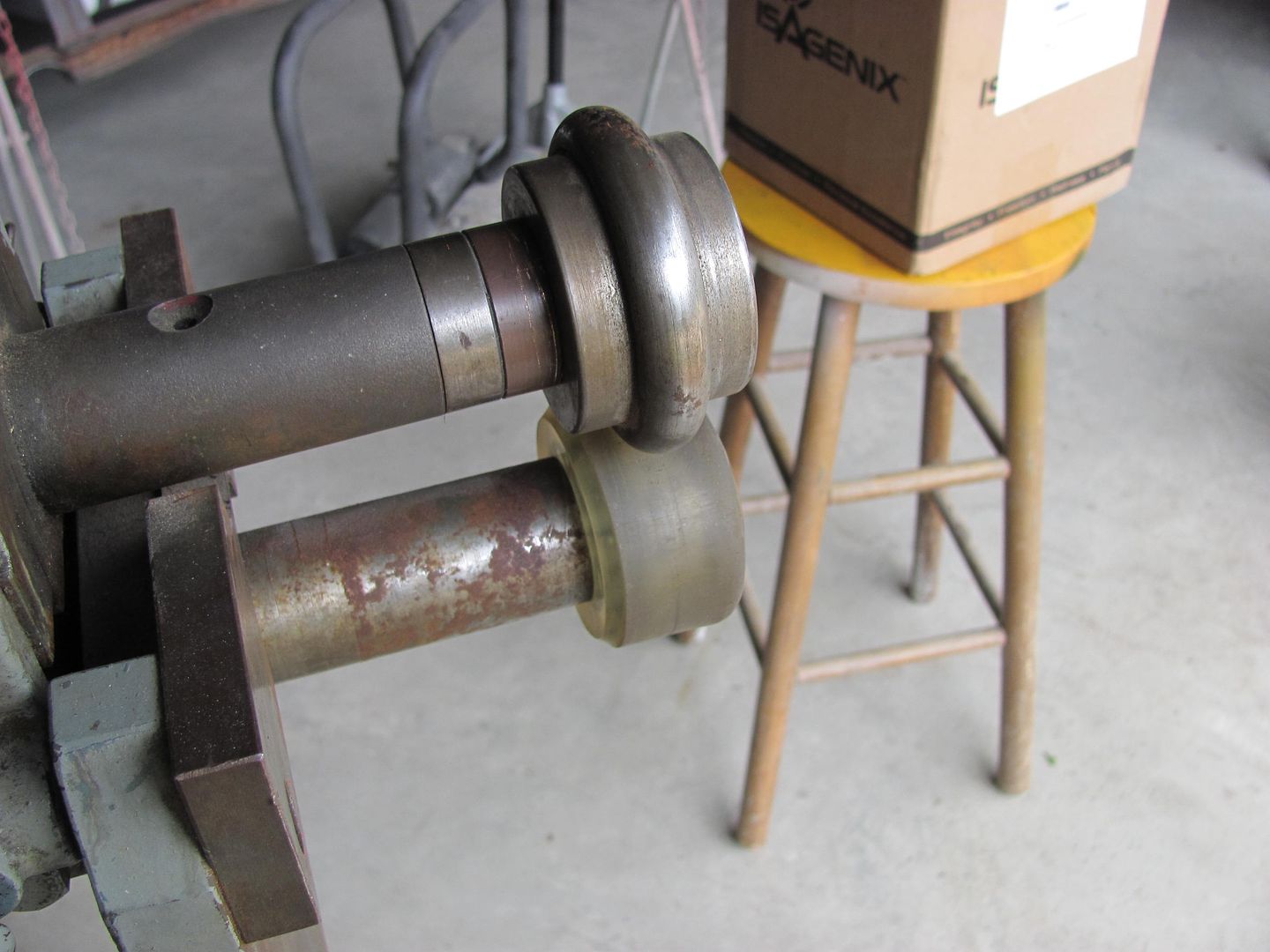
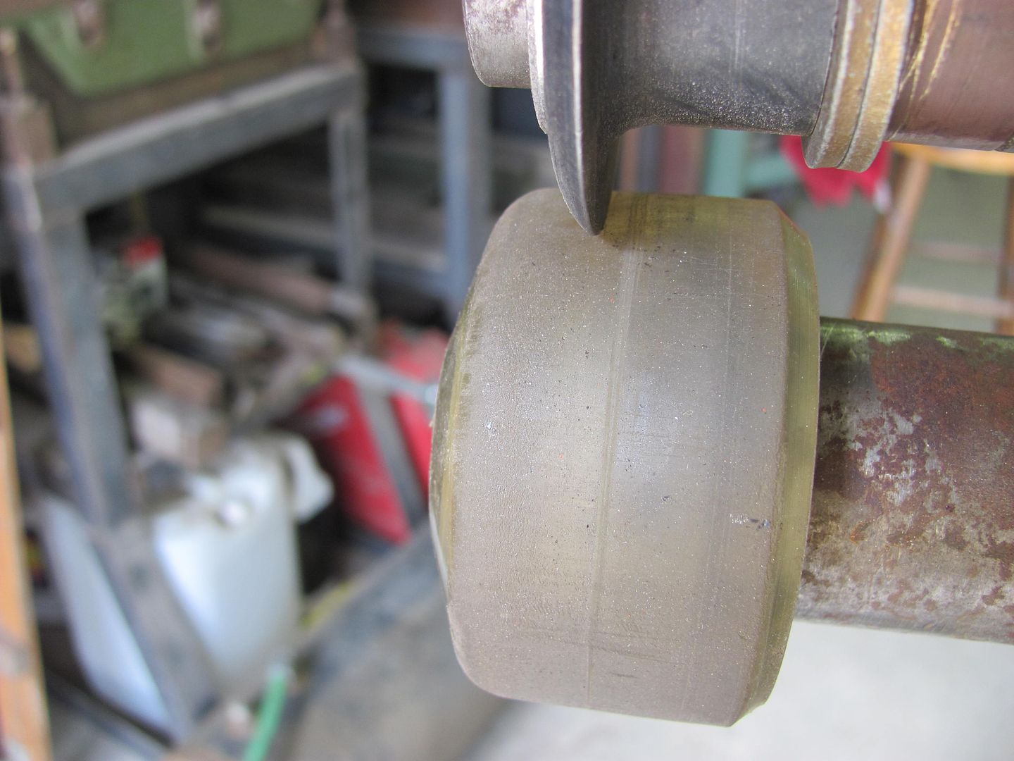
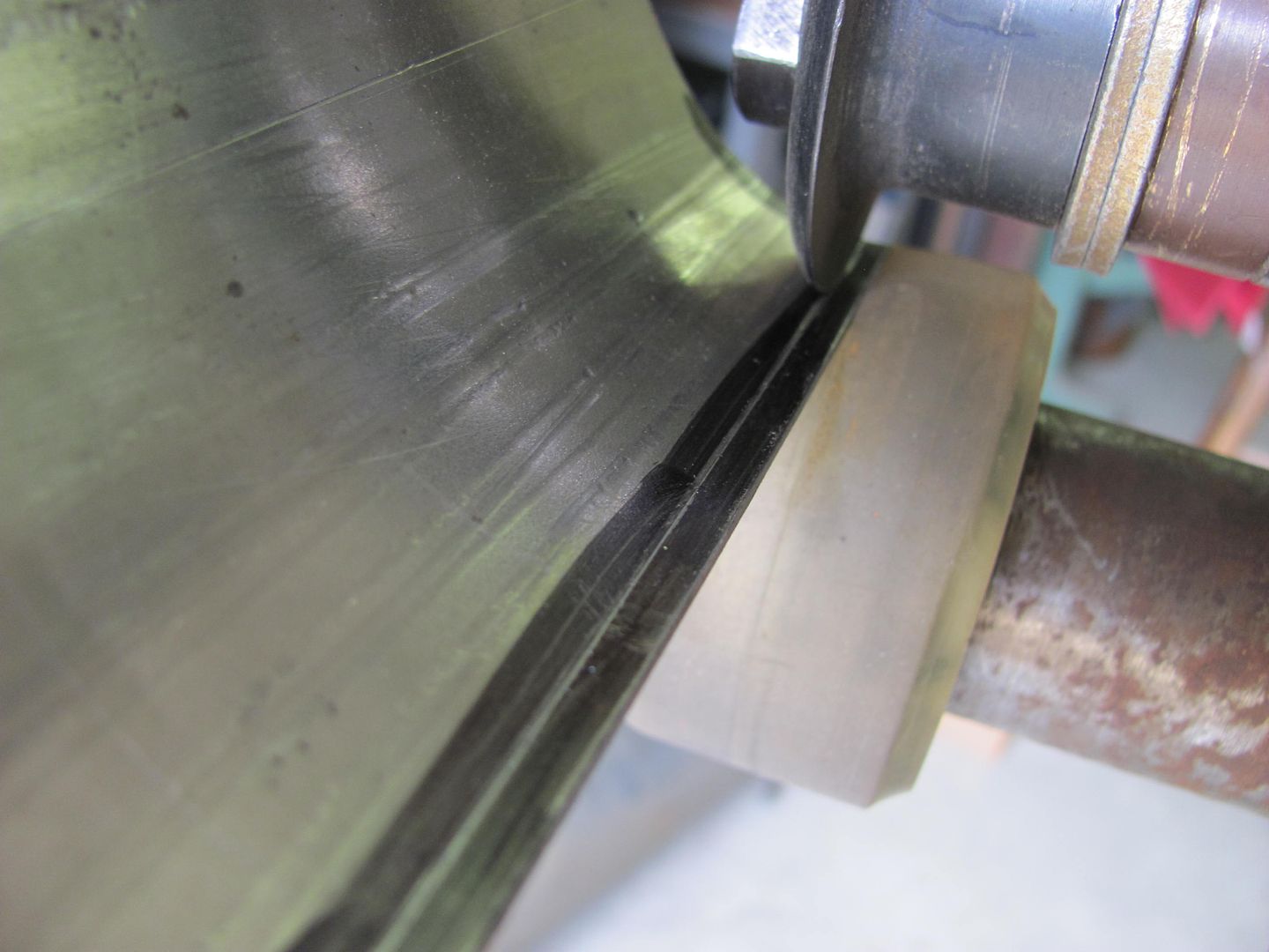
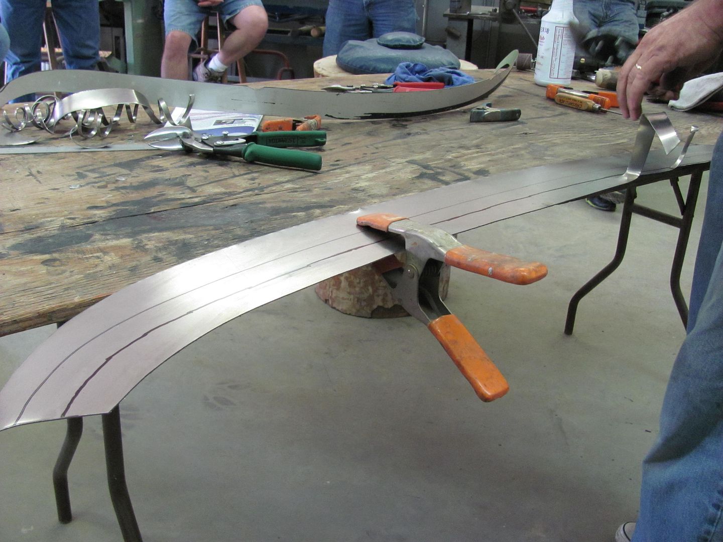
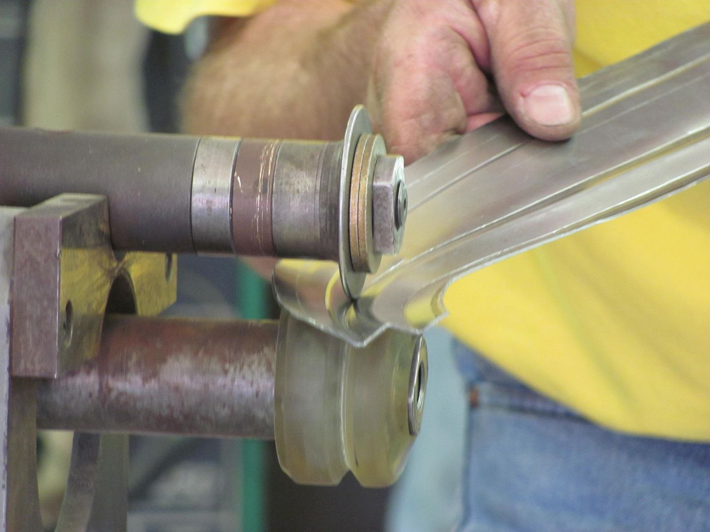
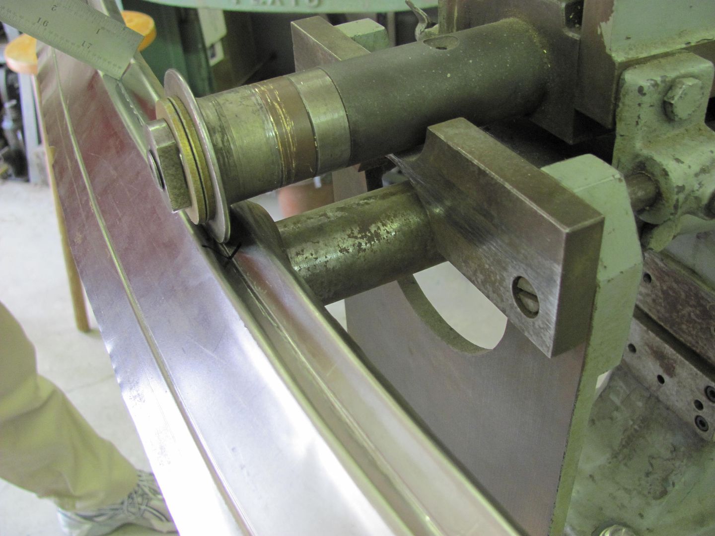
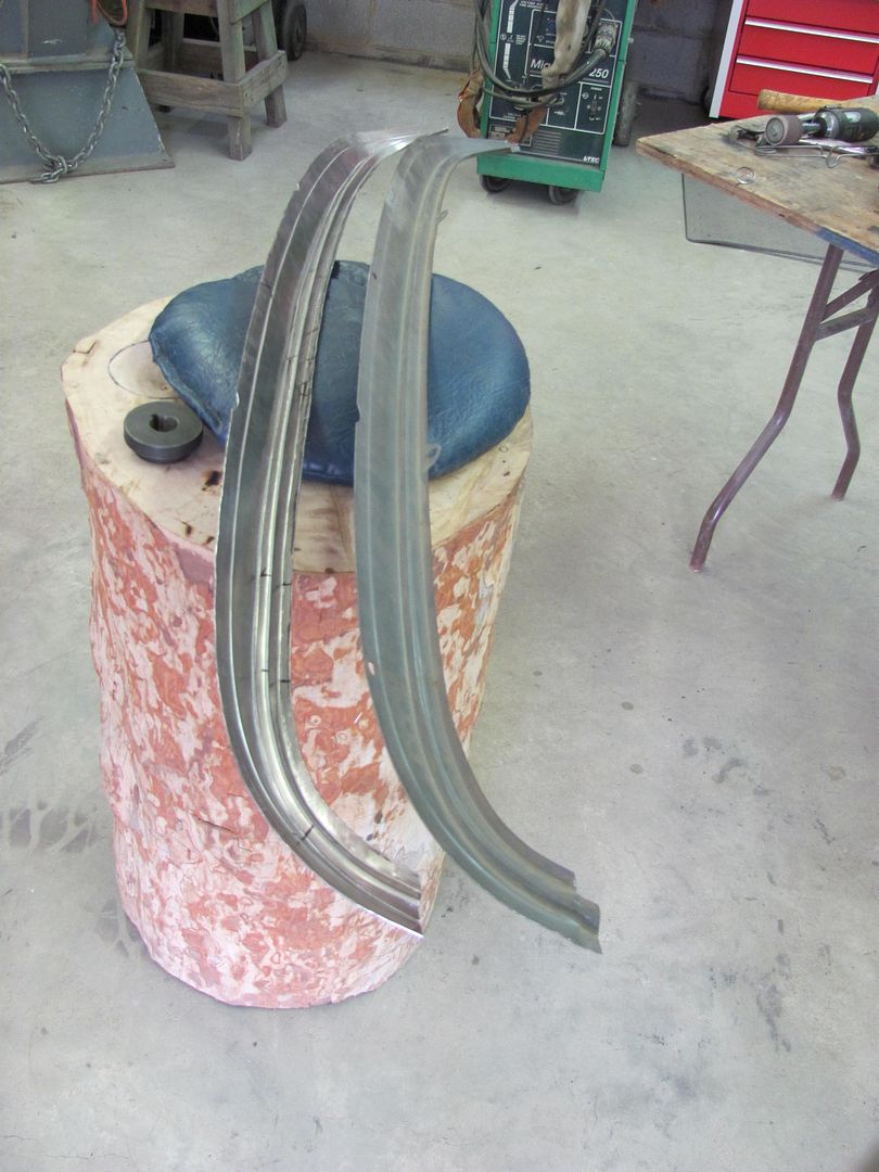
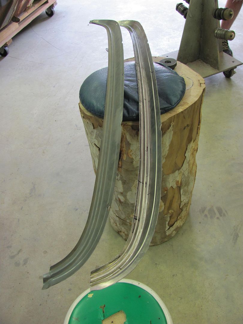
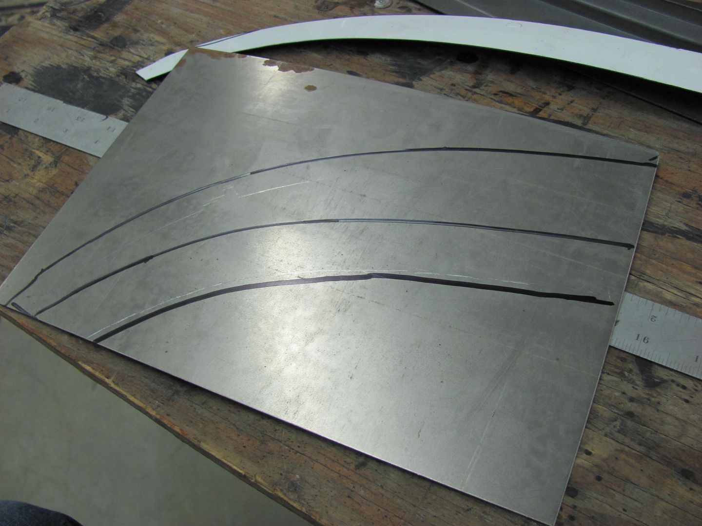
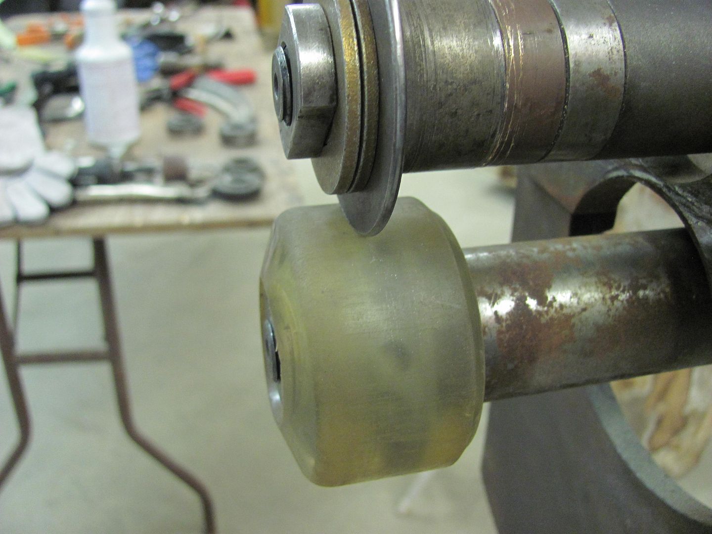
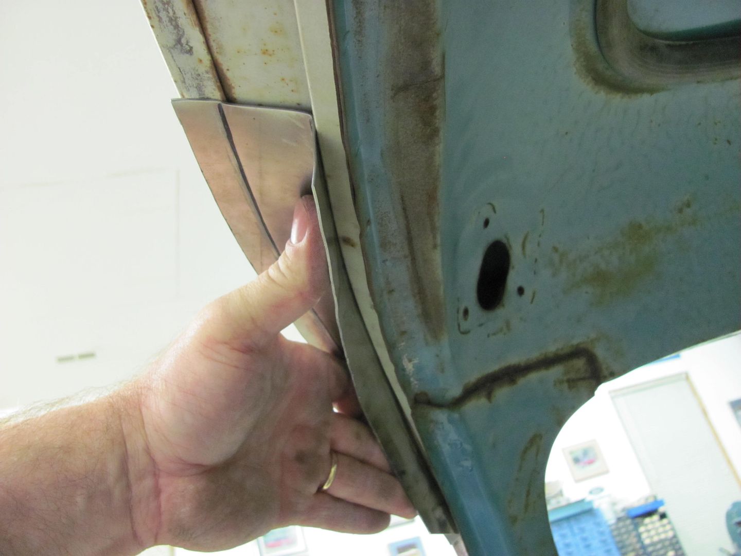
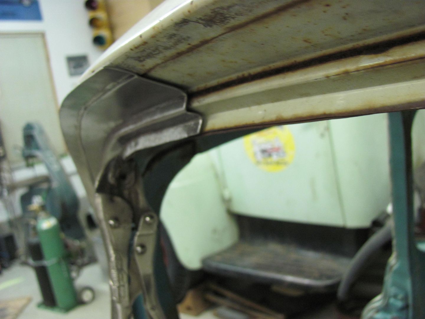
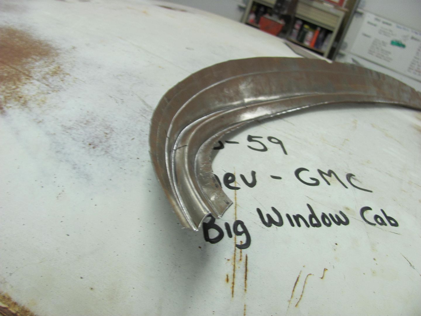
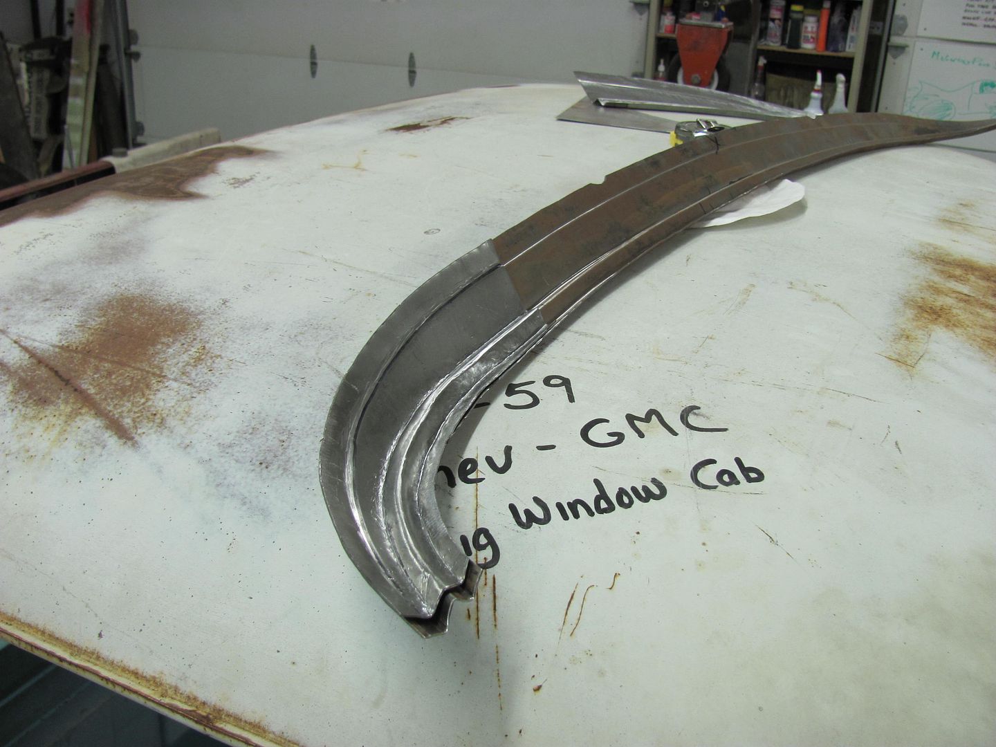
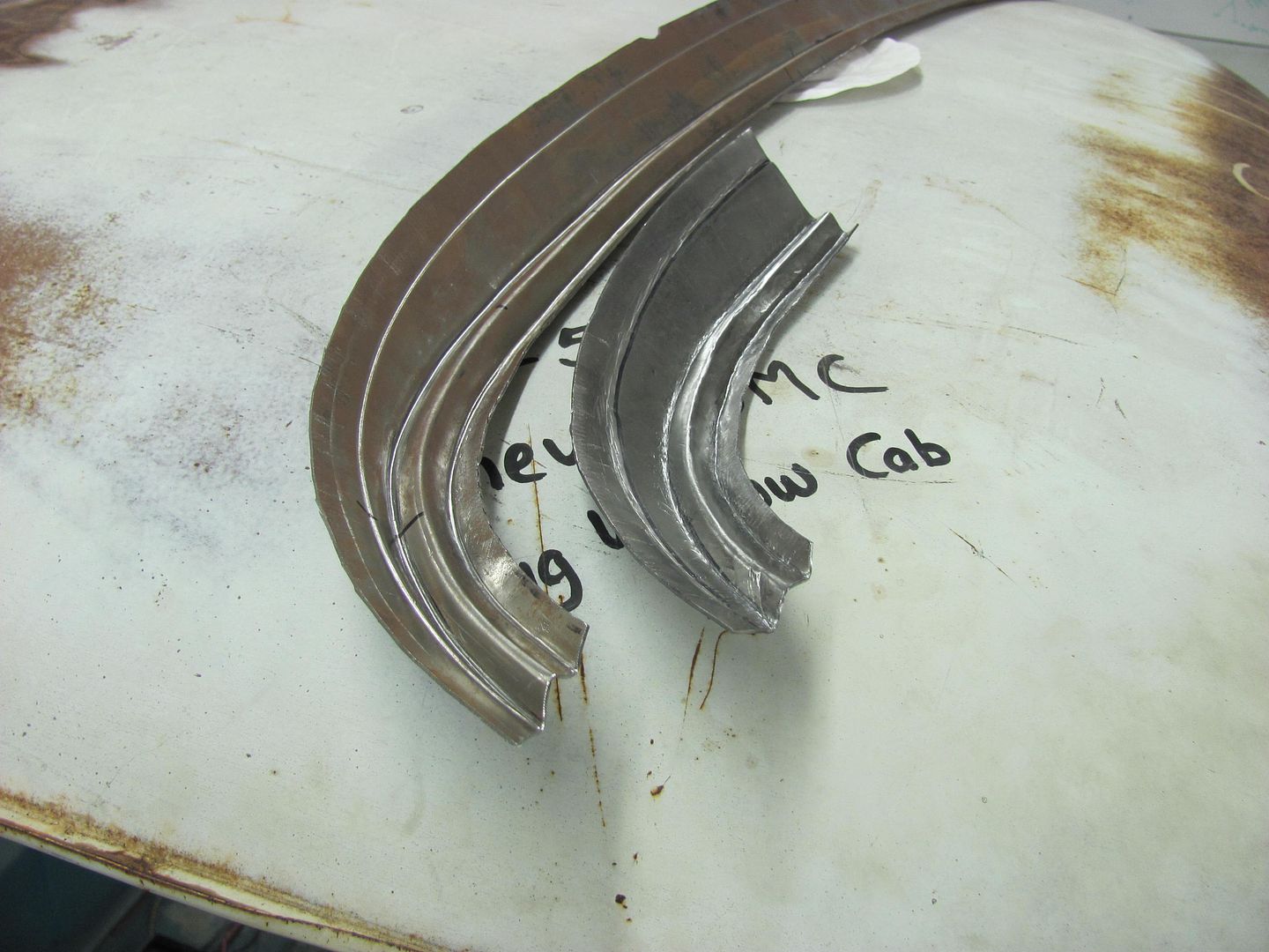
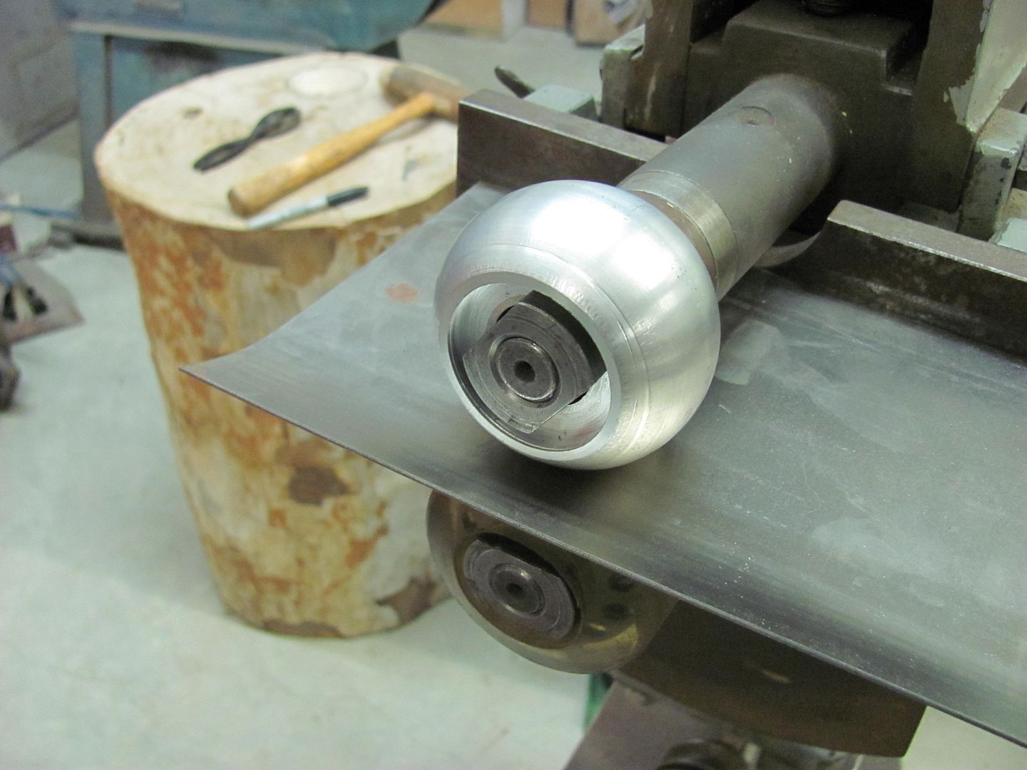
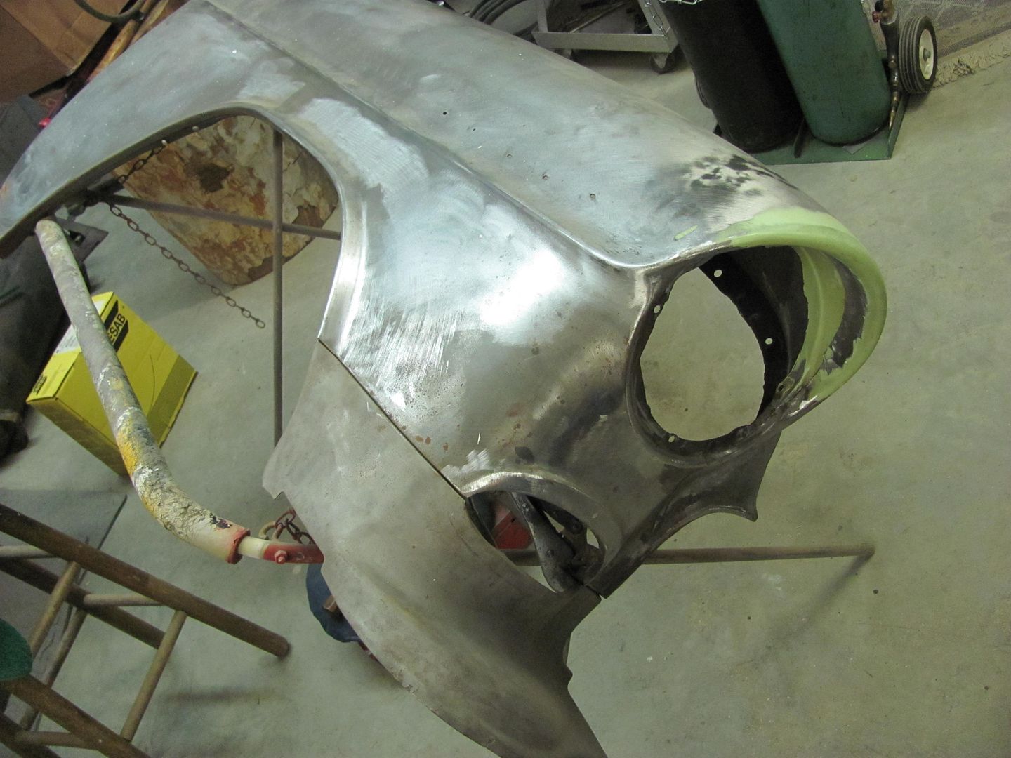
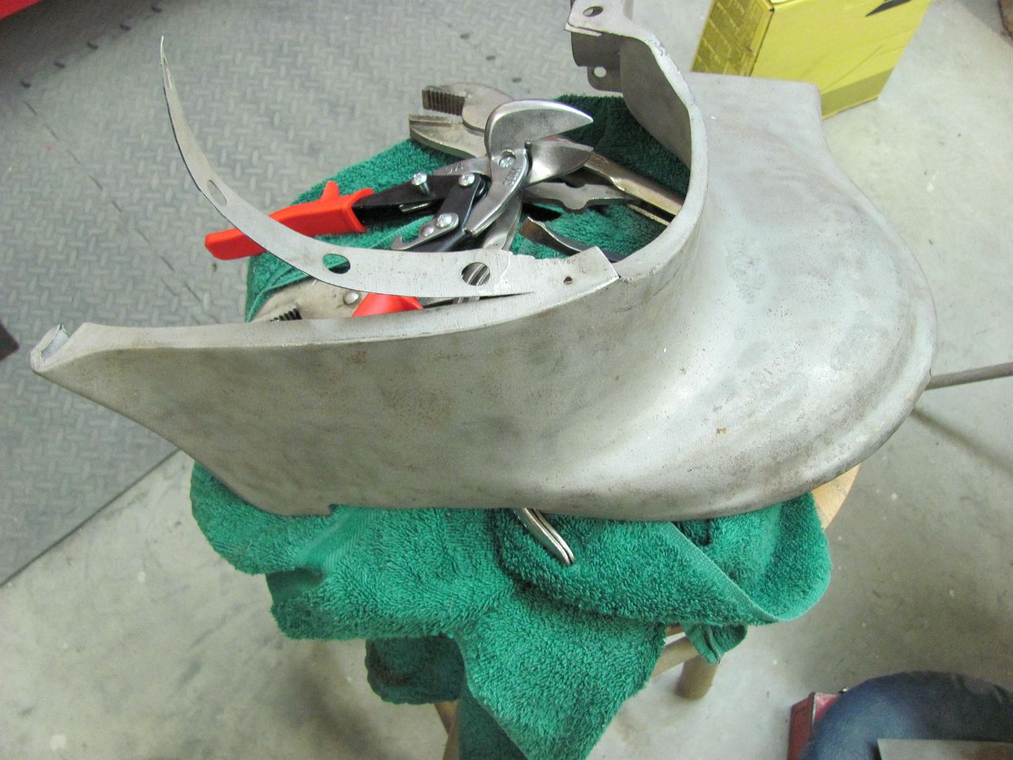
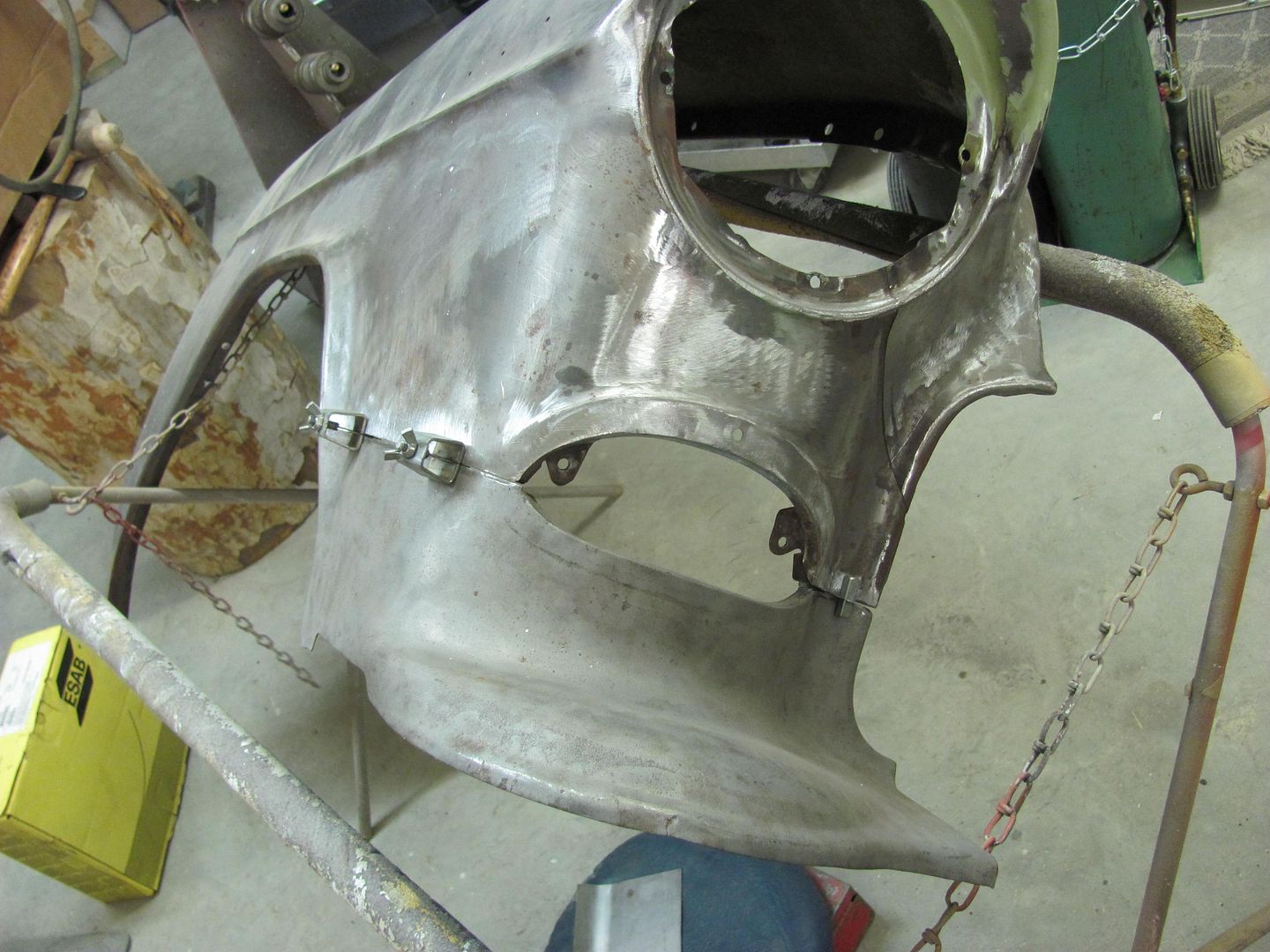
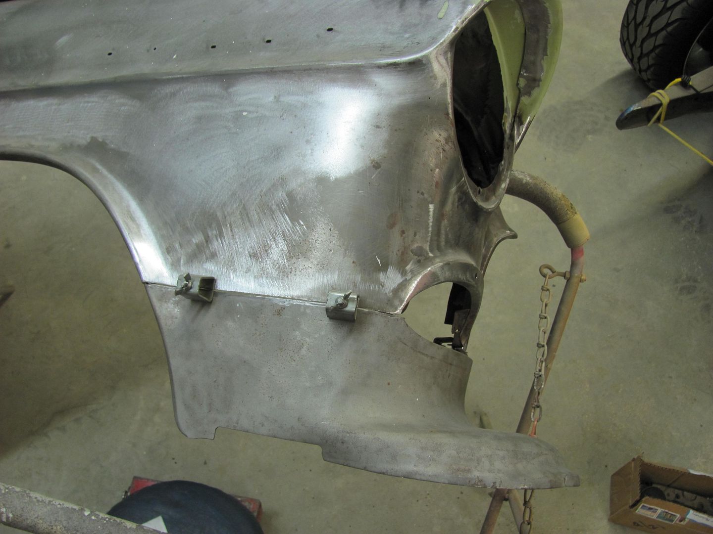
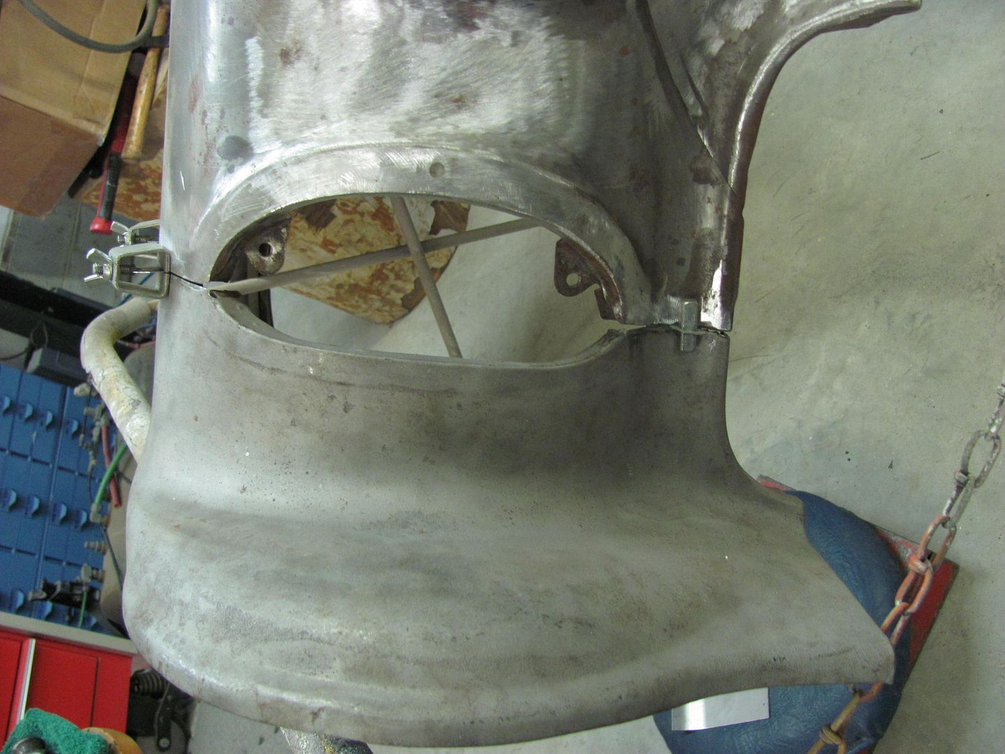
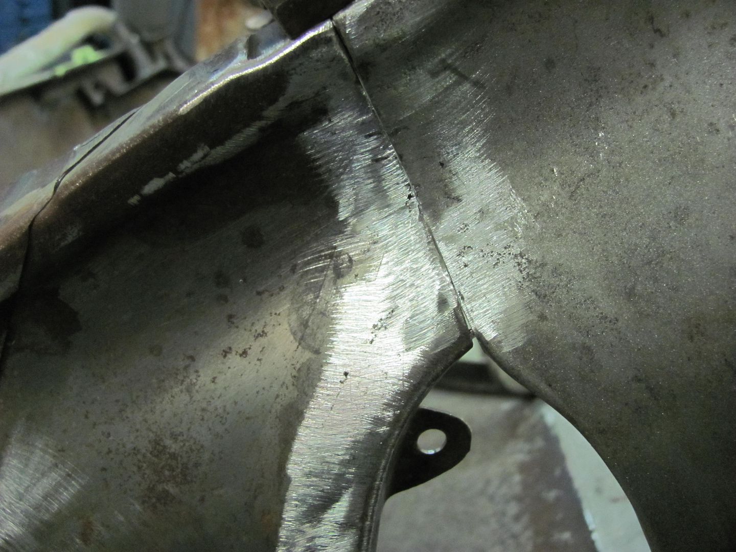
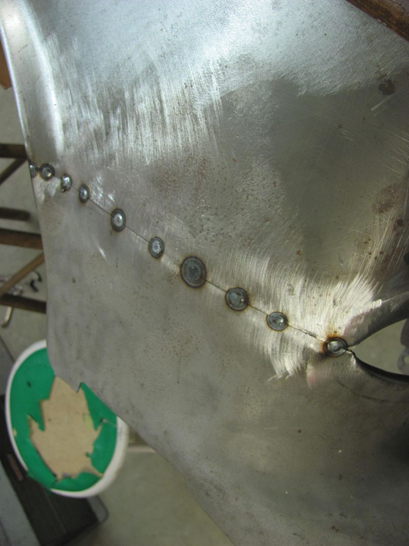
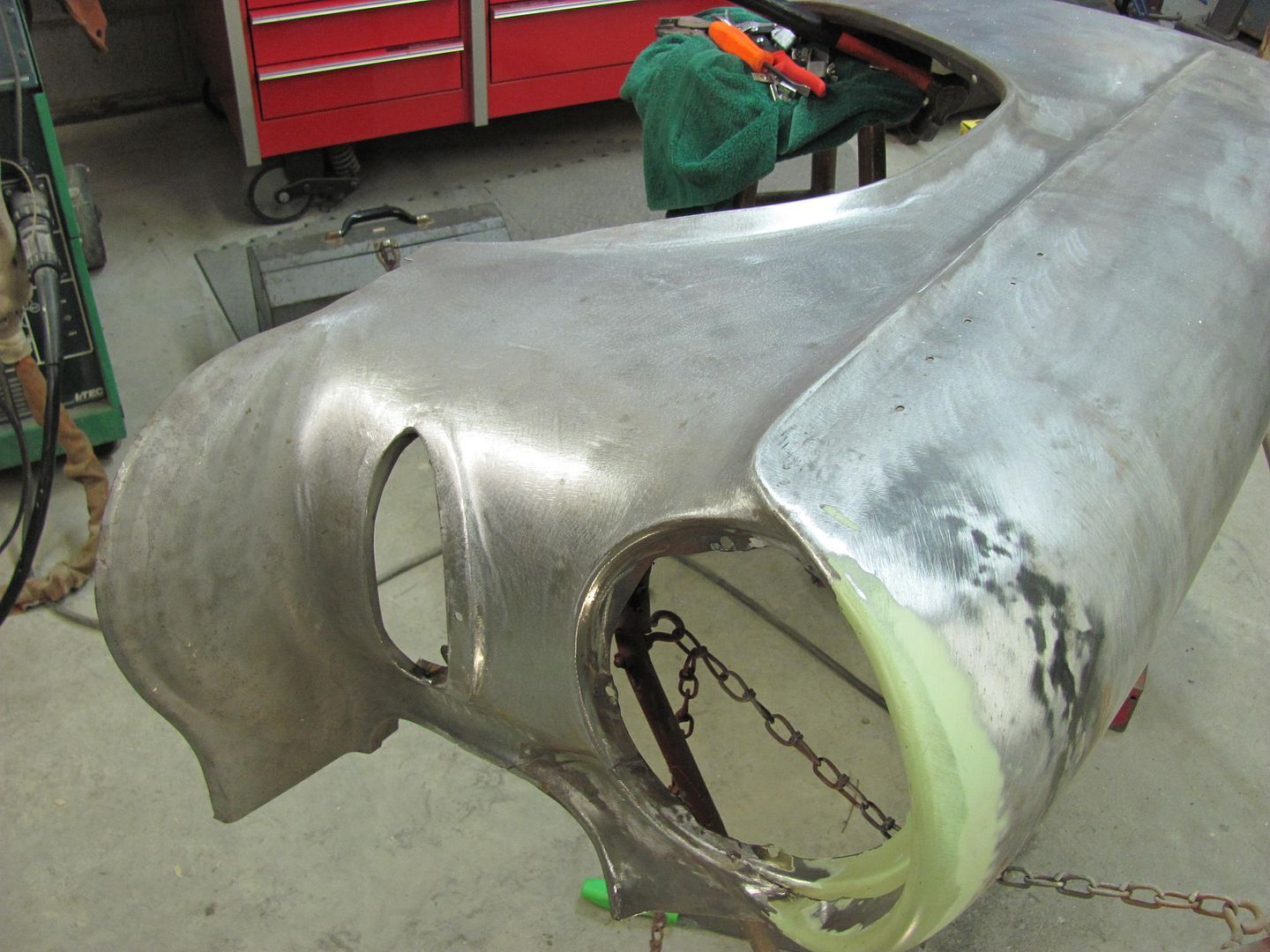
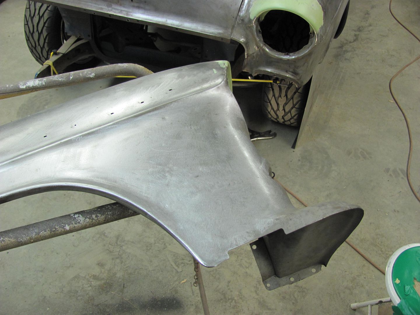
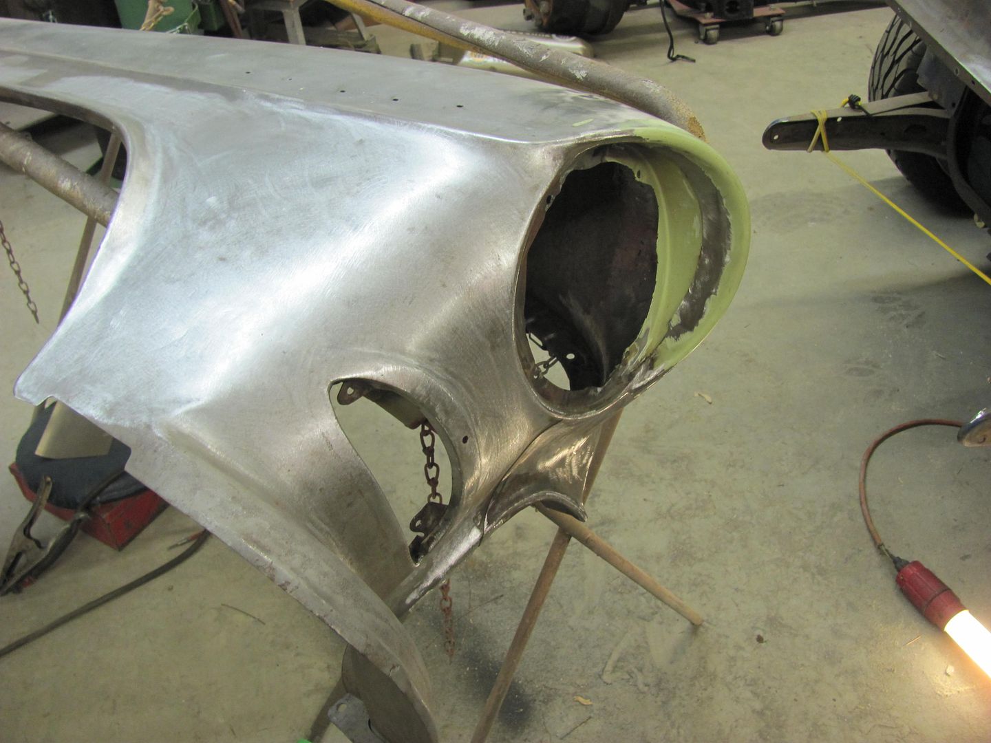
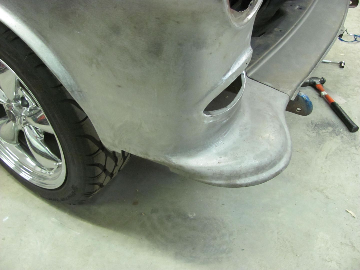
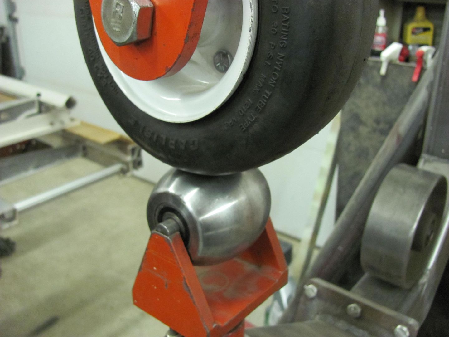
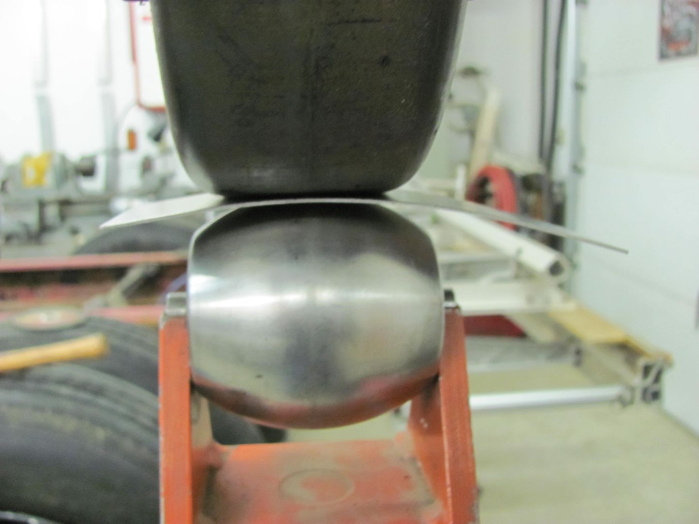
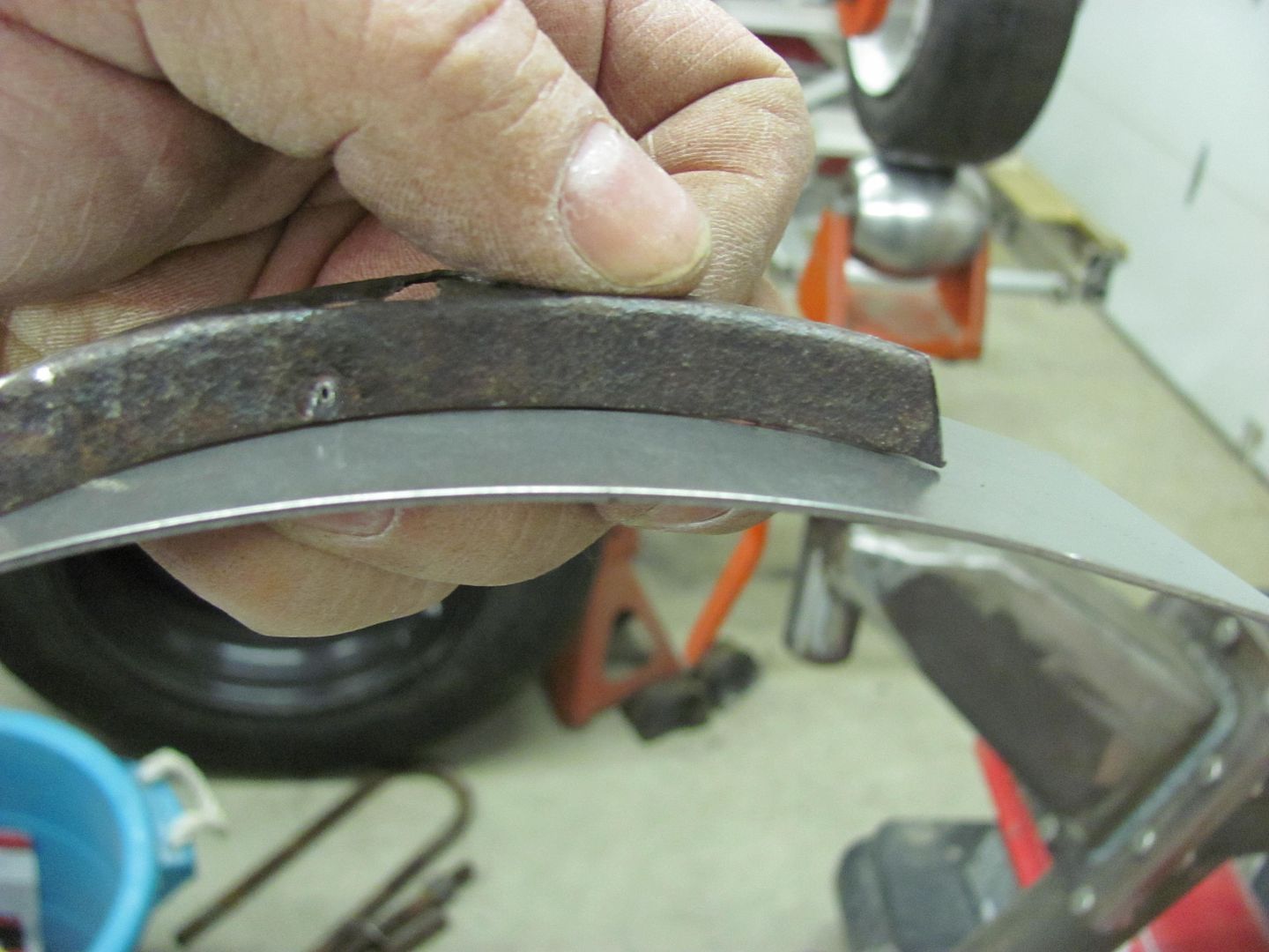
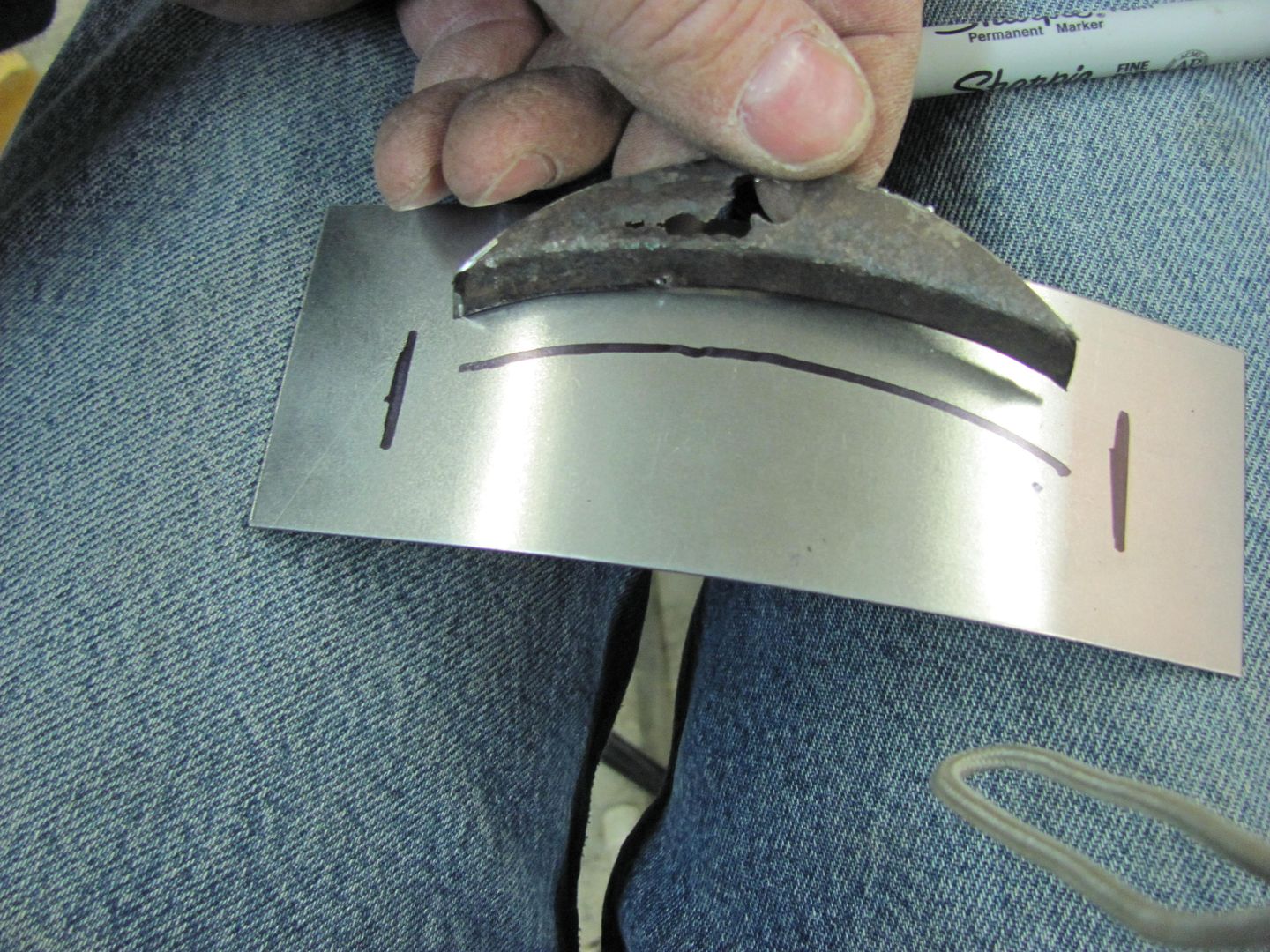
Did you use a bead roller to get the definition in the metal?
Looks very good by the way.
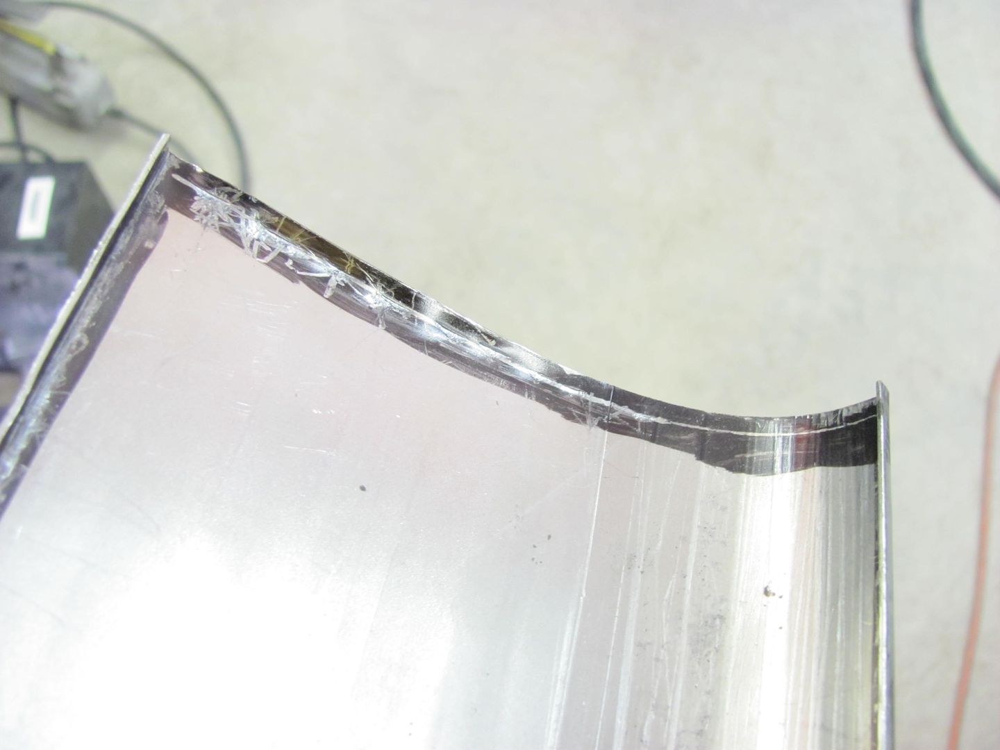
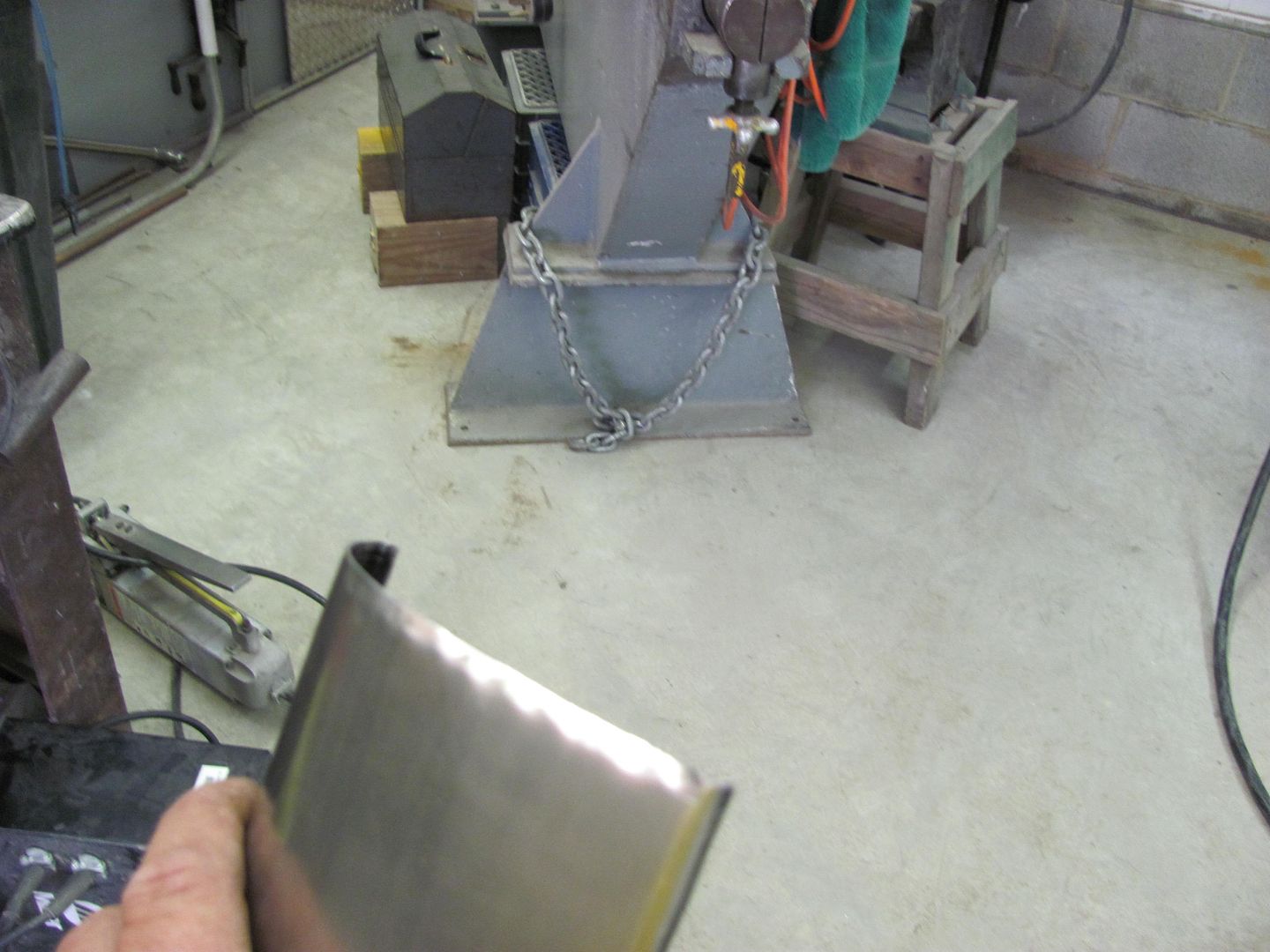
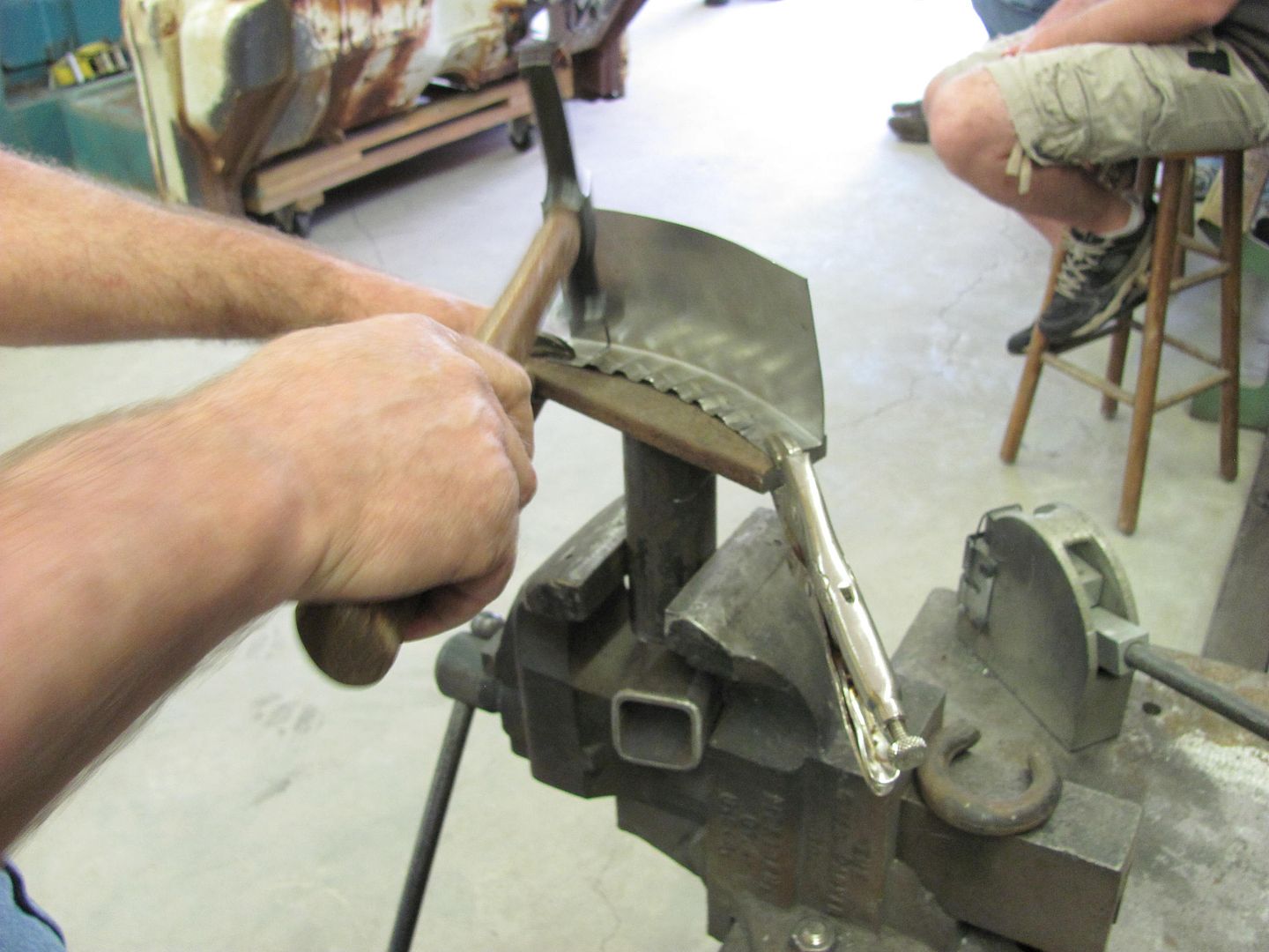
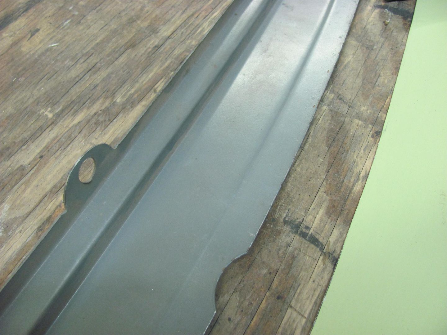
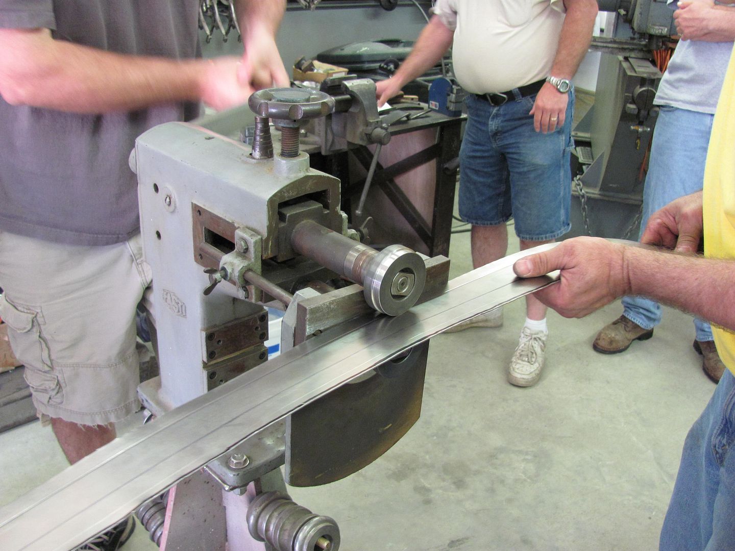
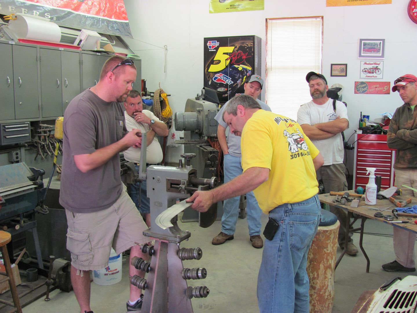
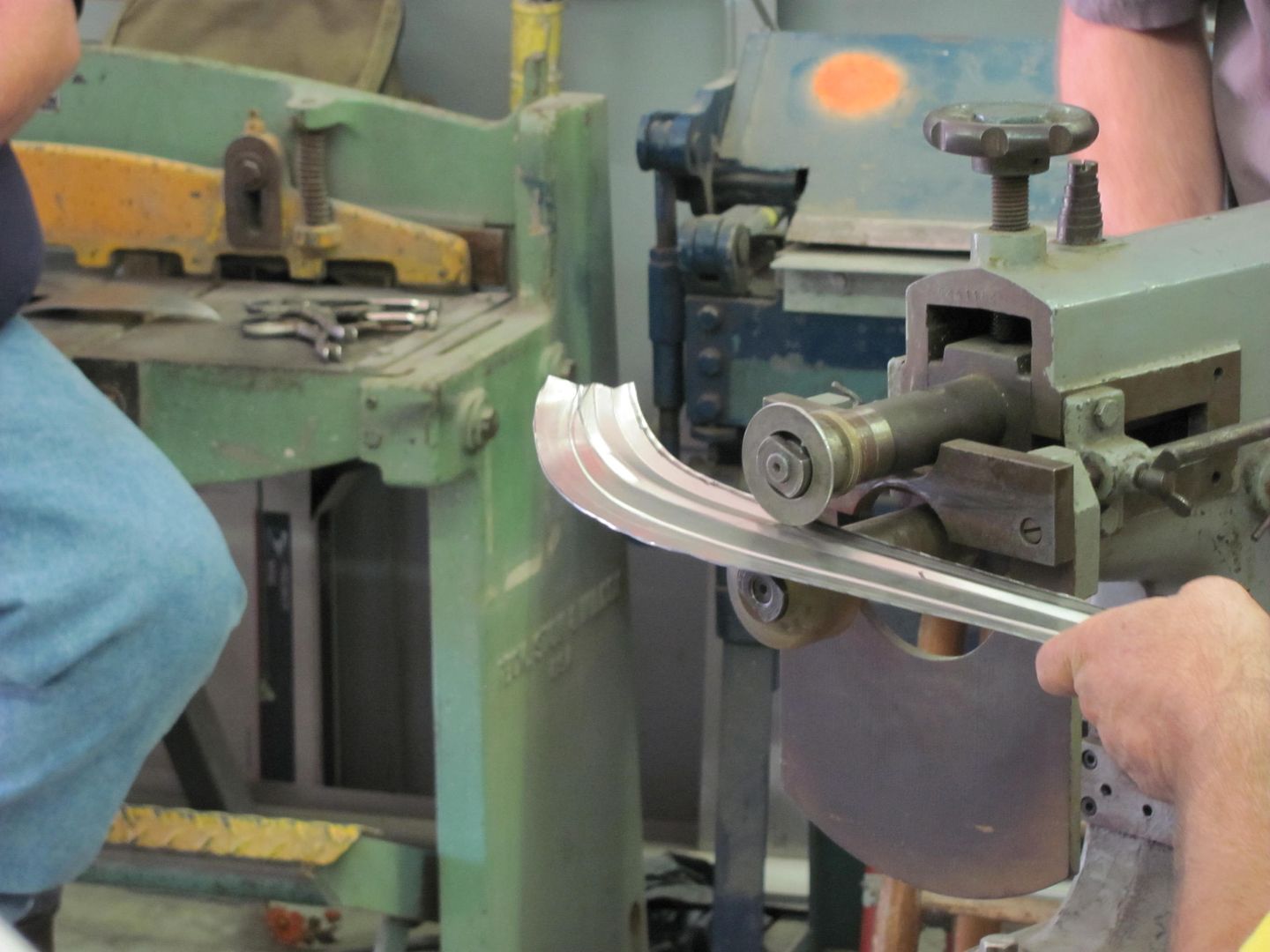
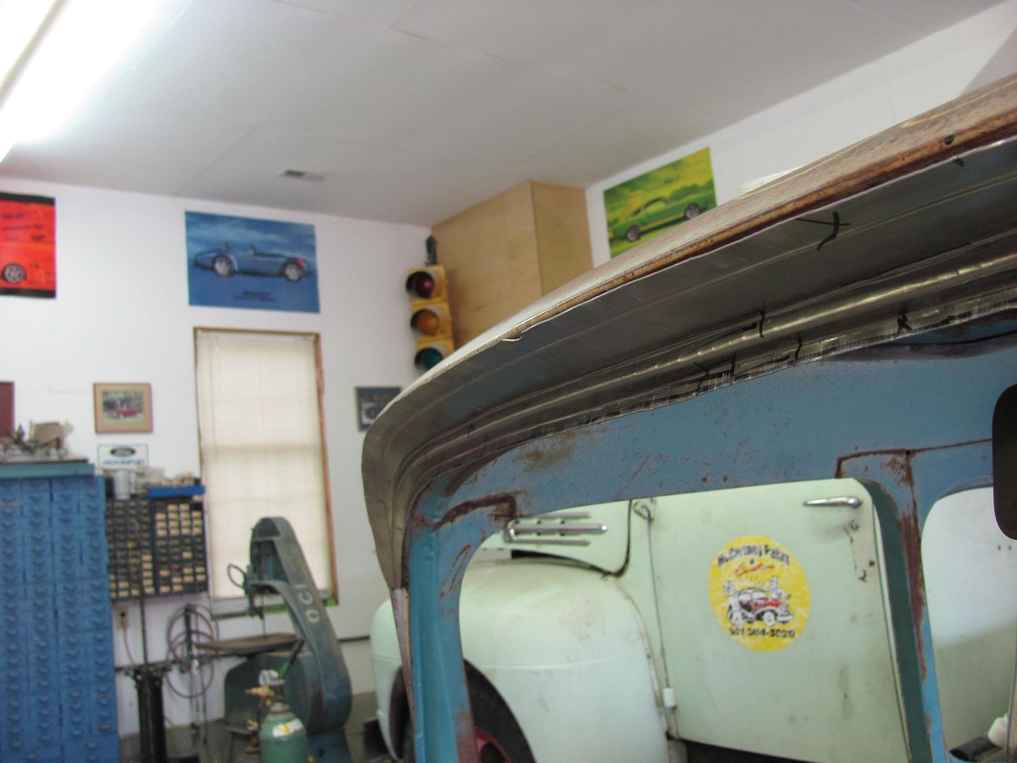
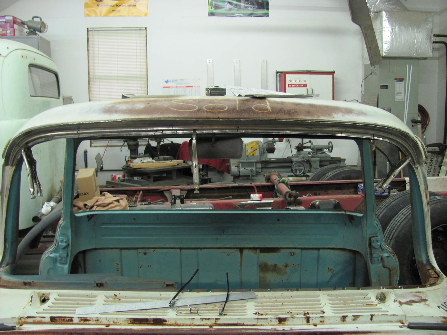
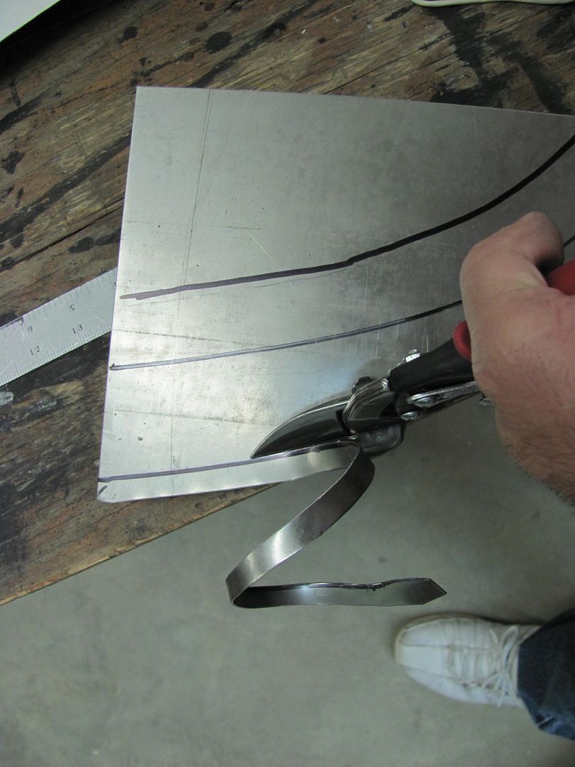
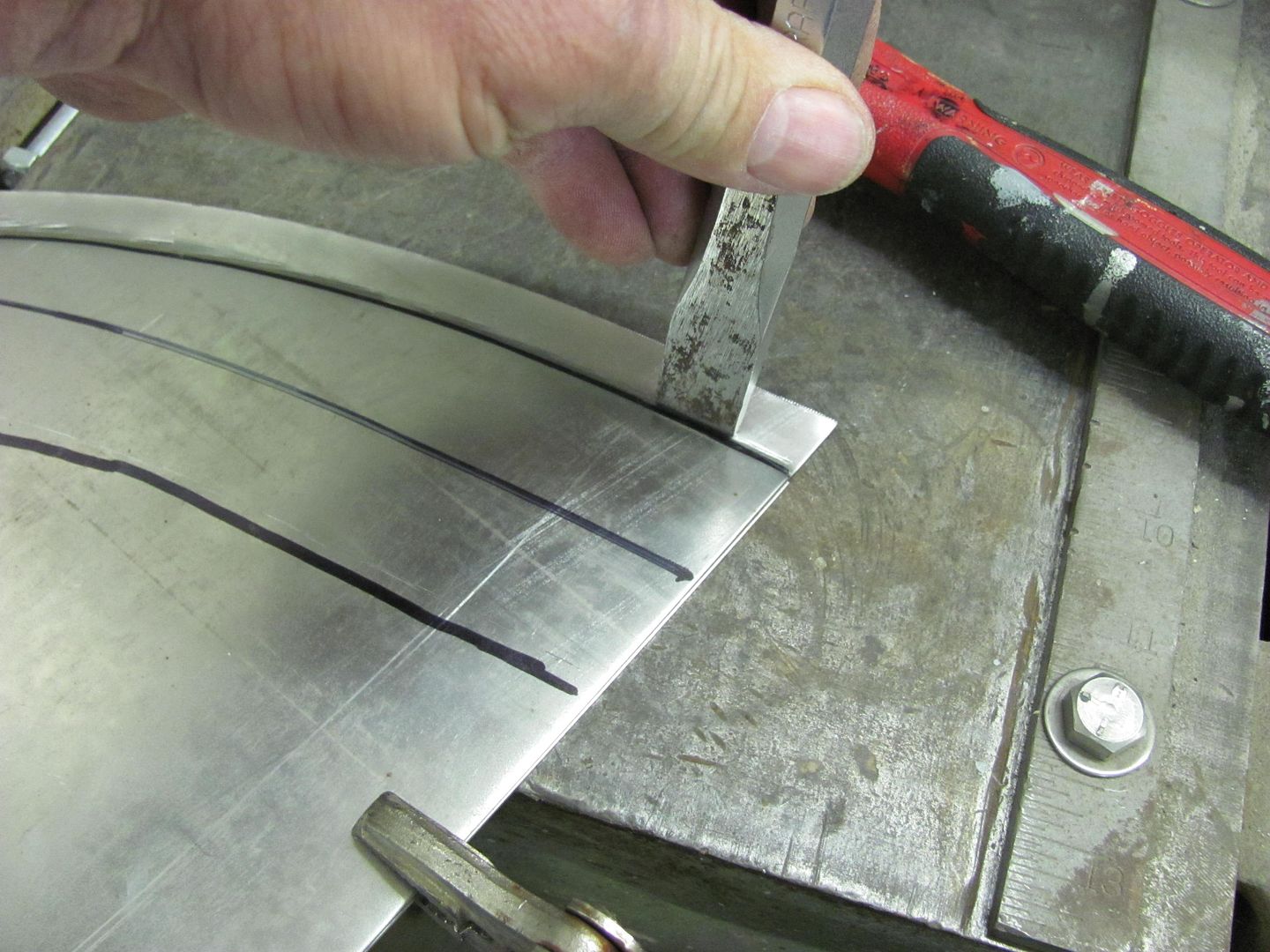
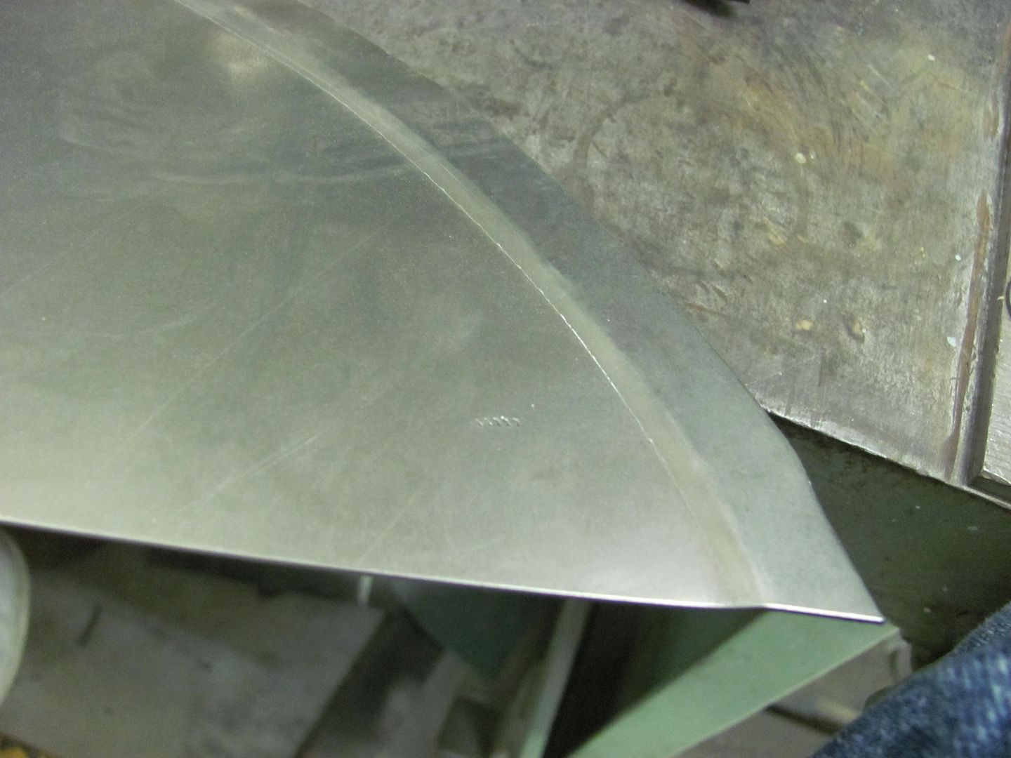
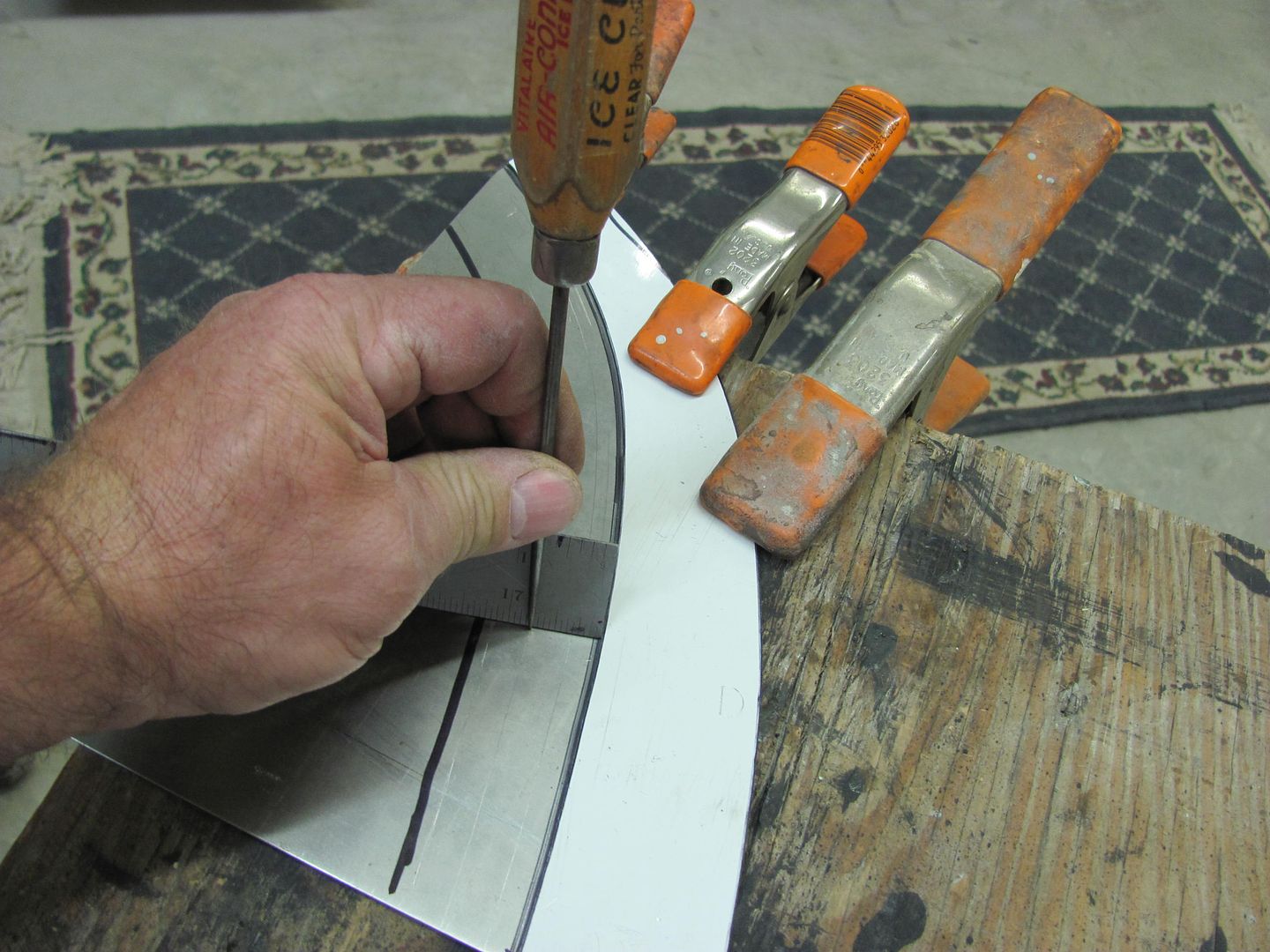
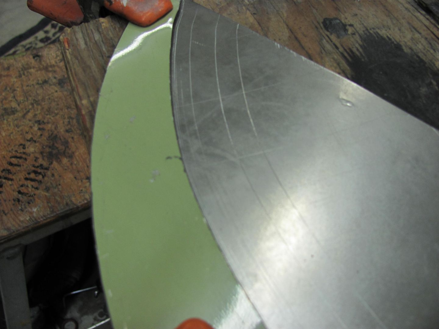
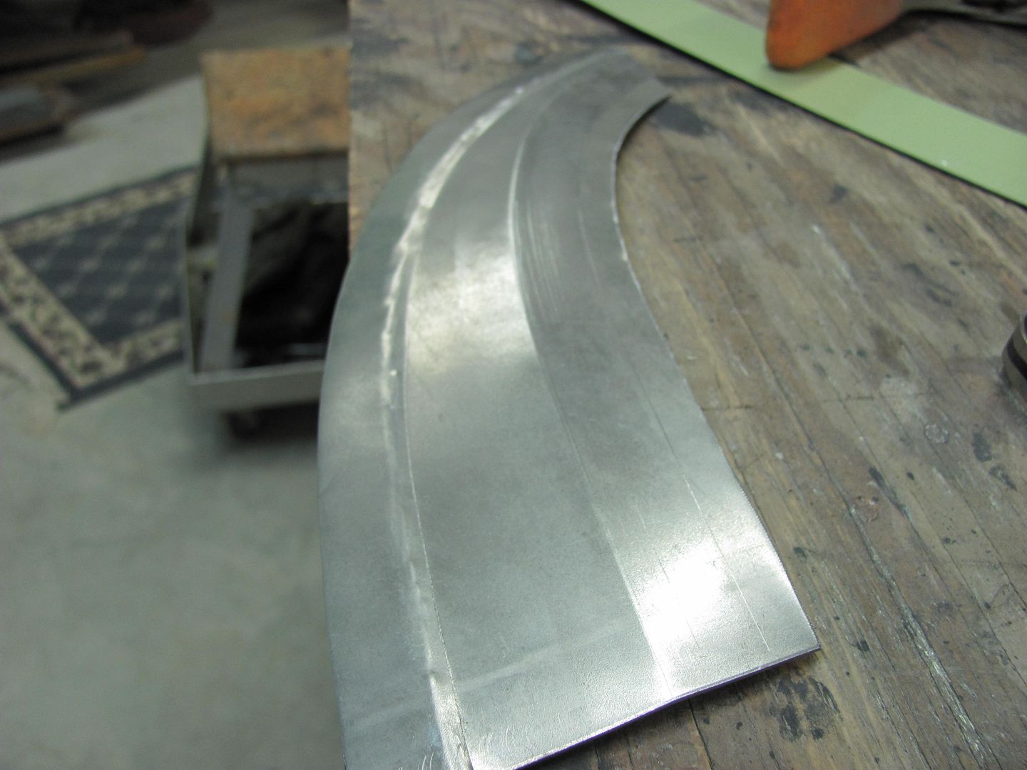
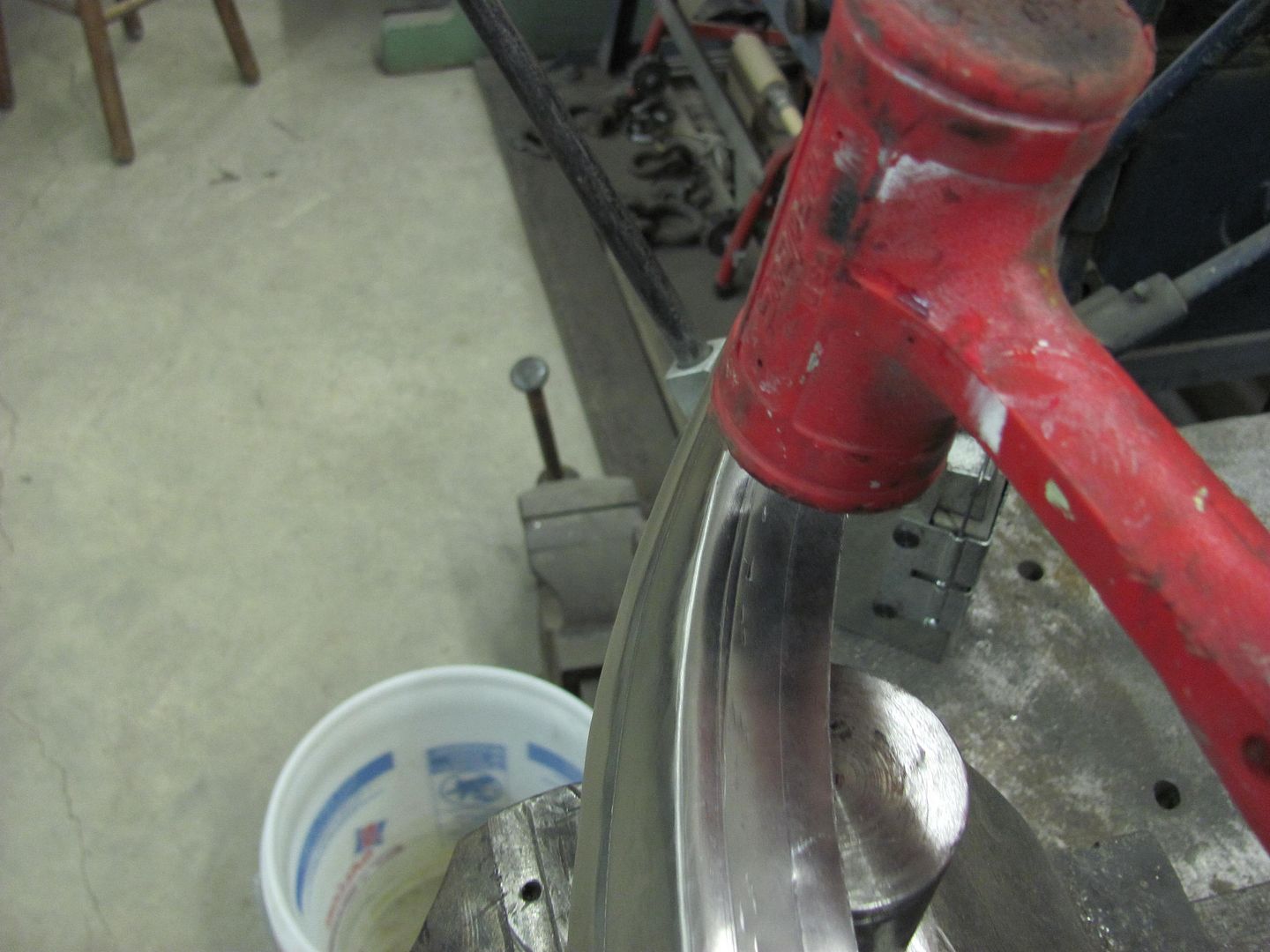
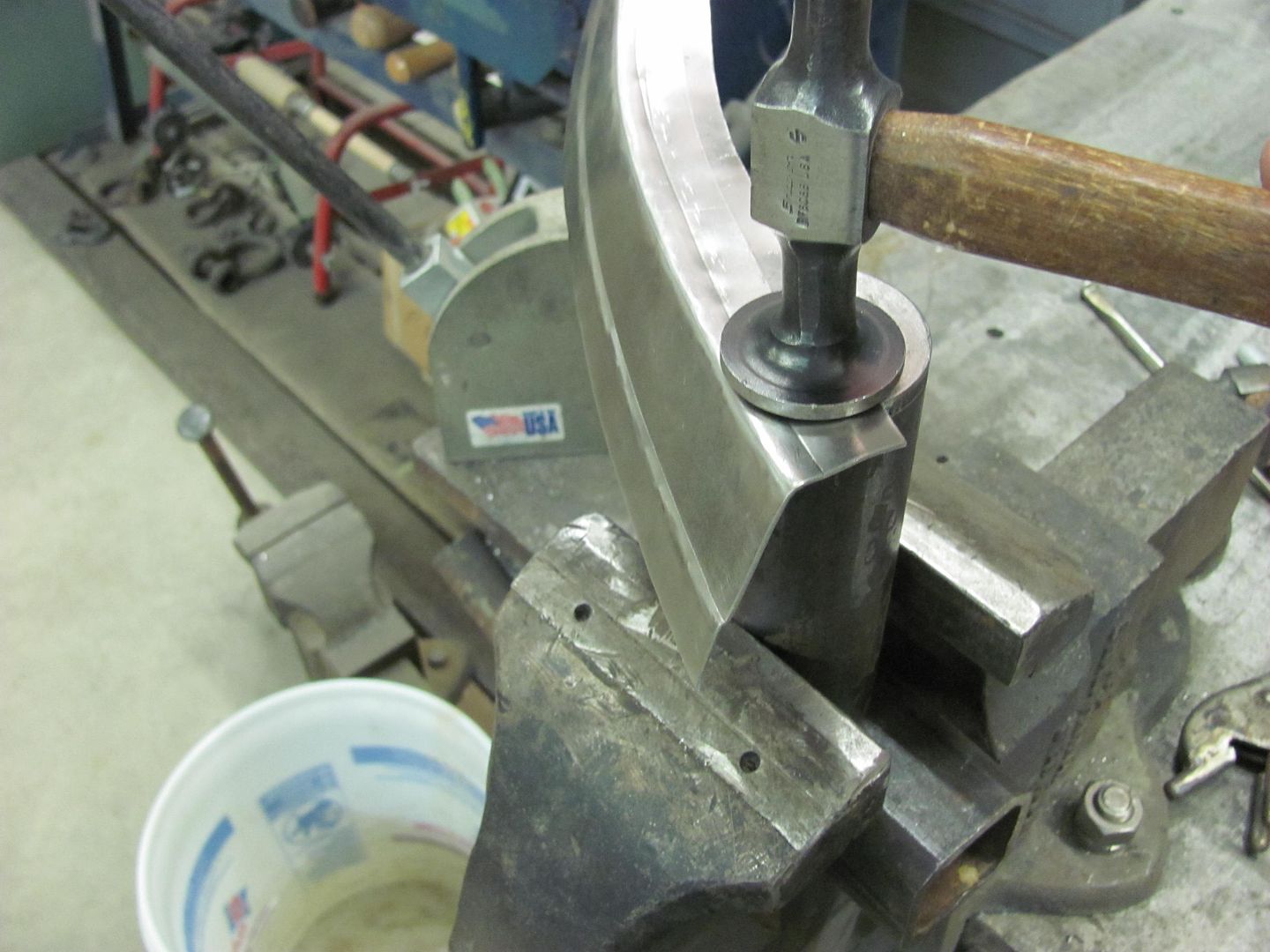
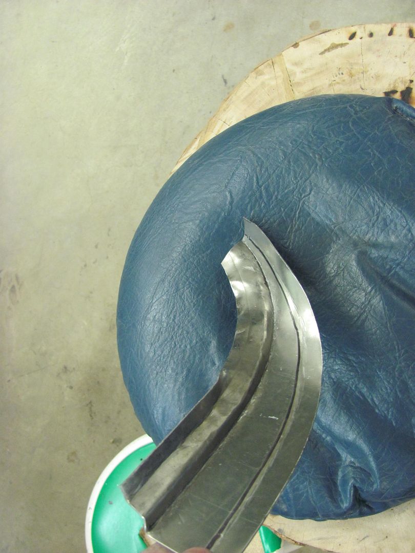
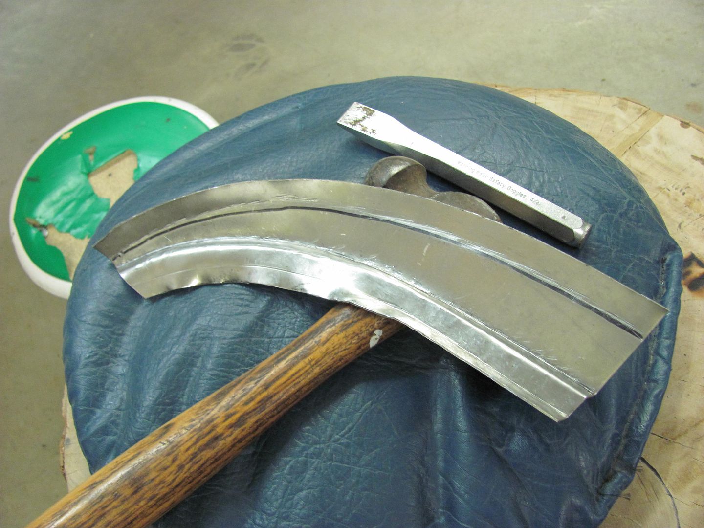
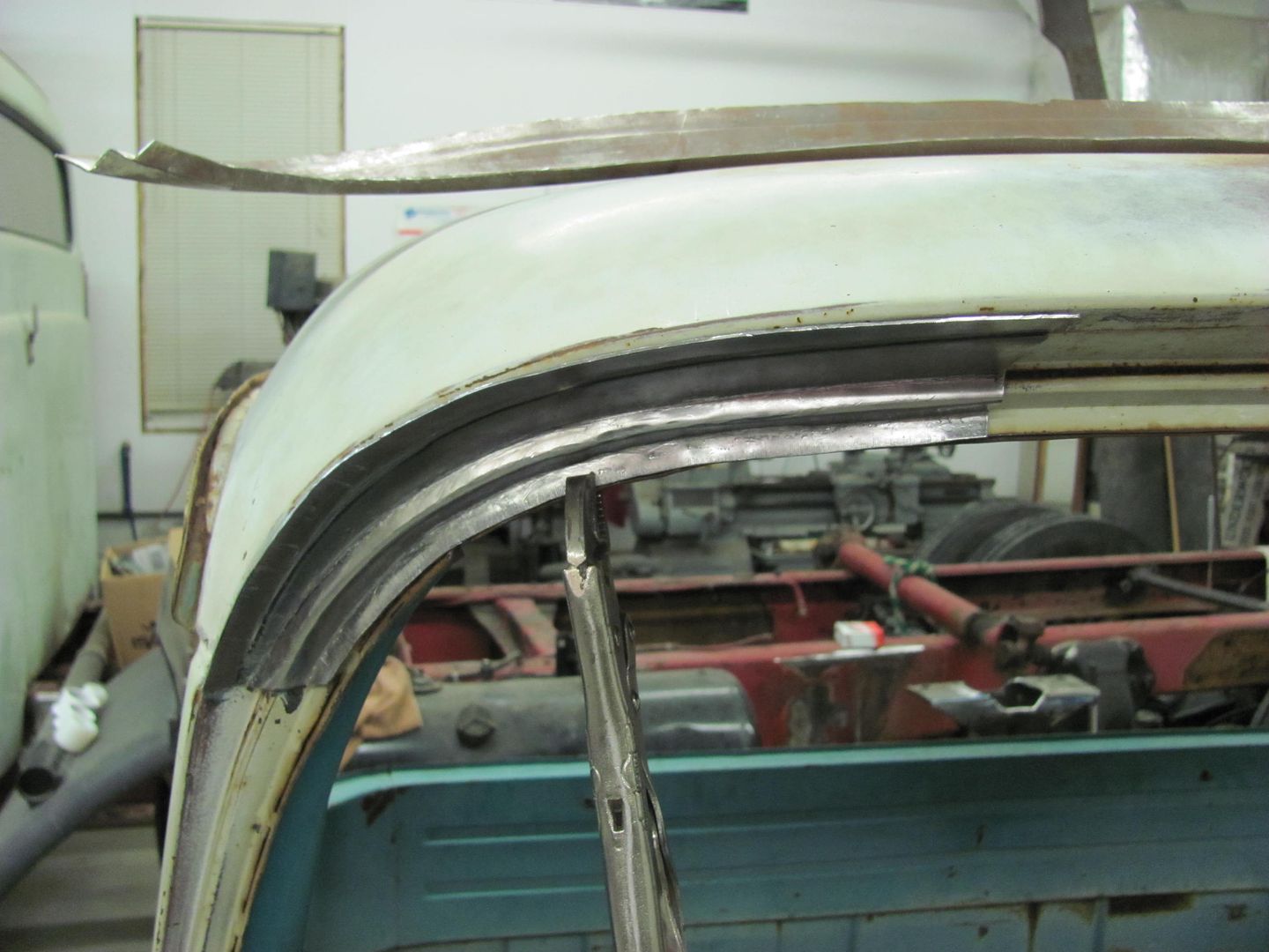
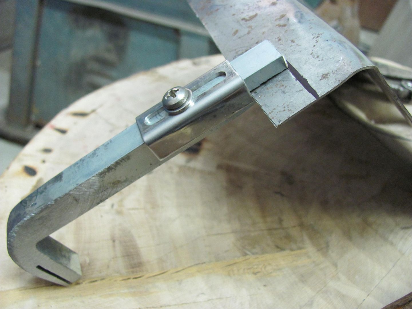
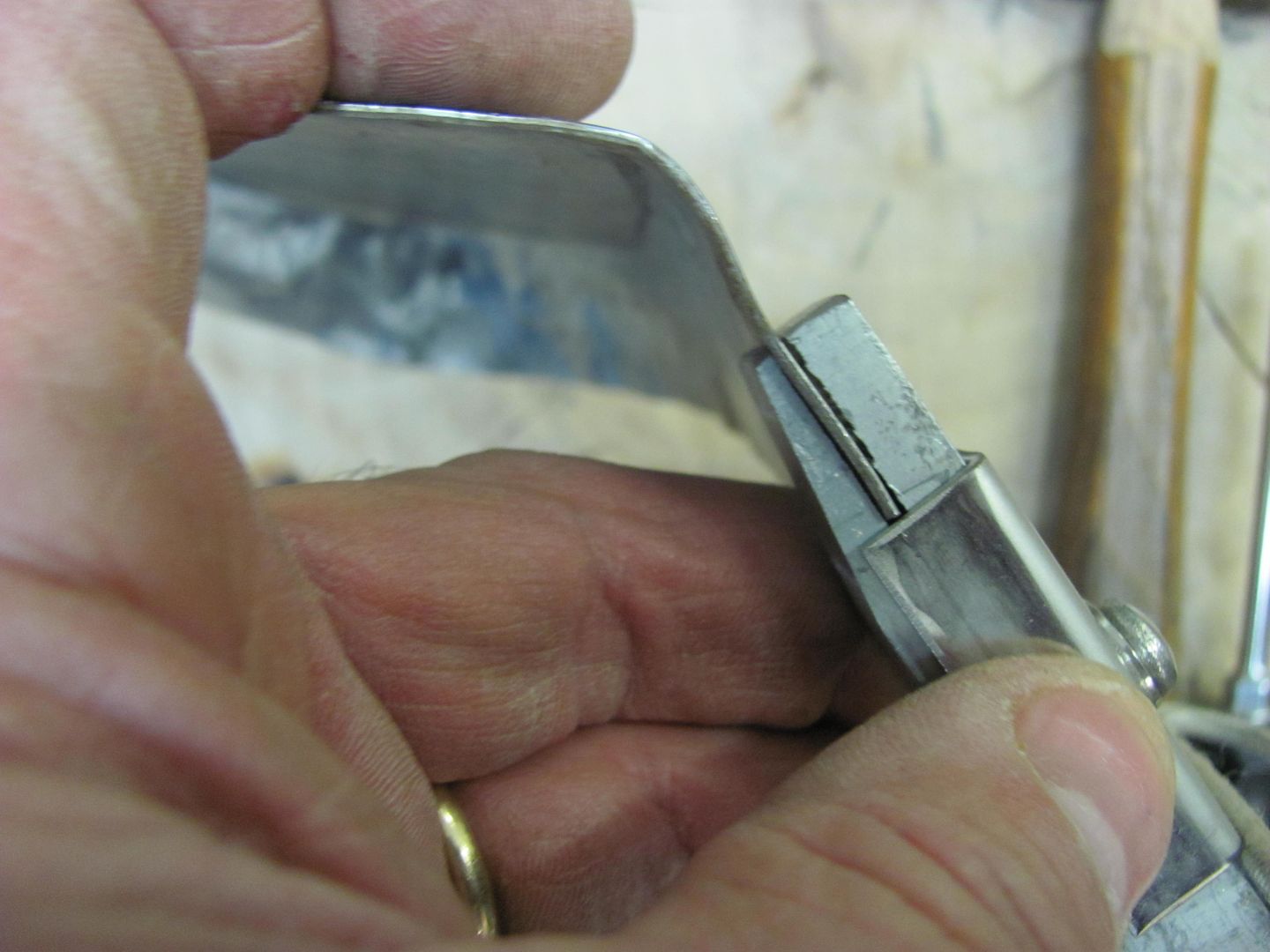
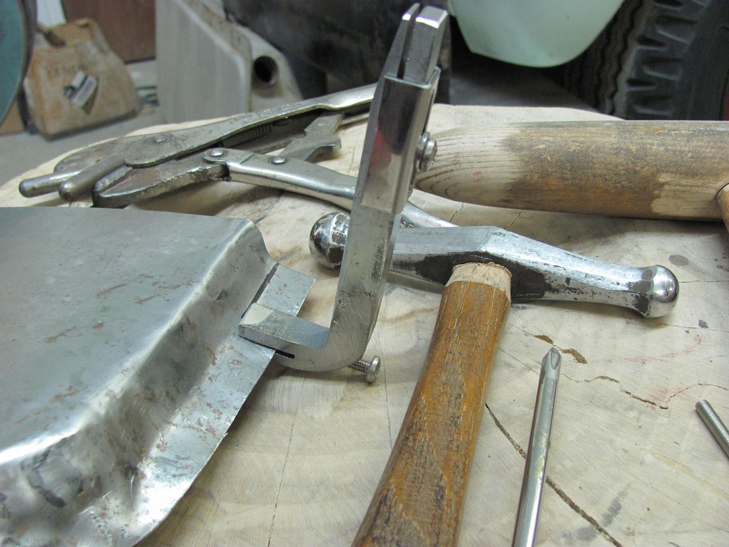
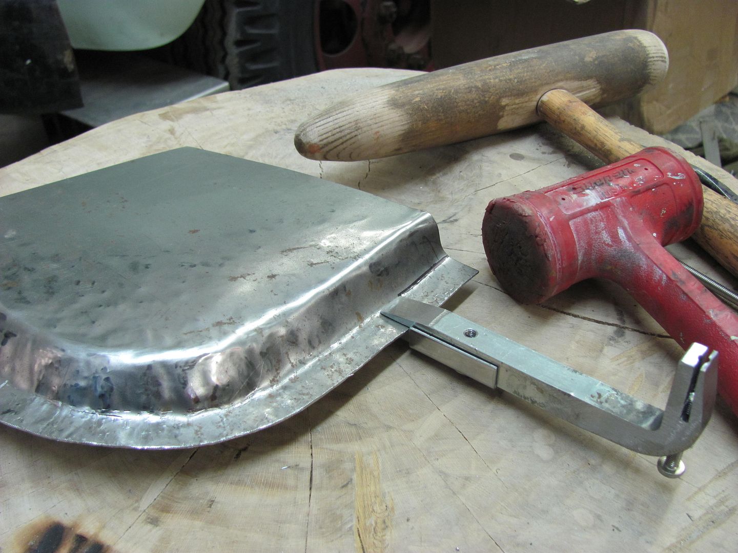
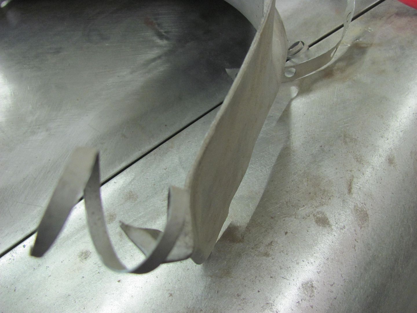
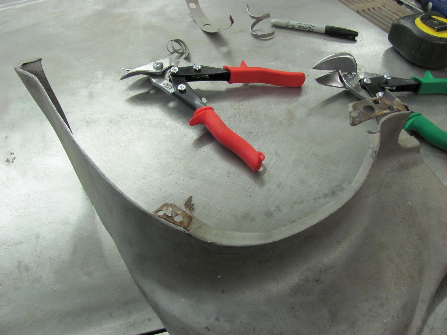
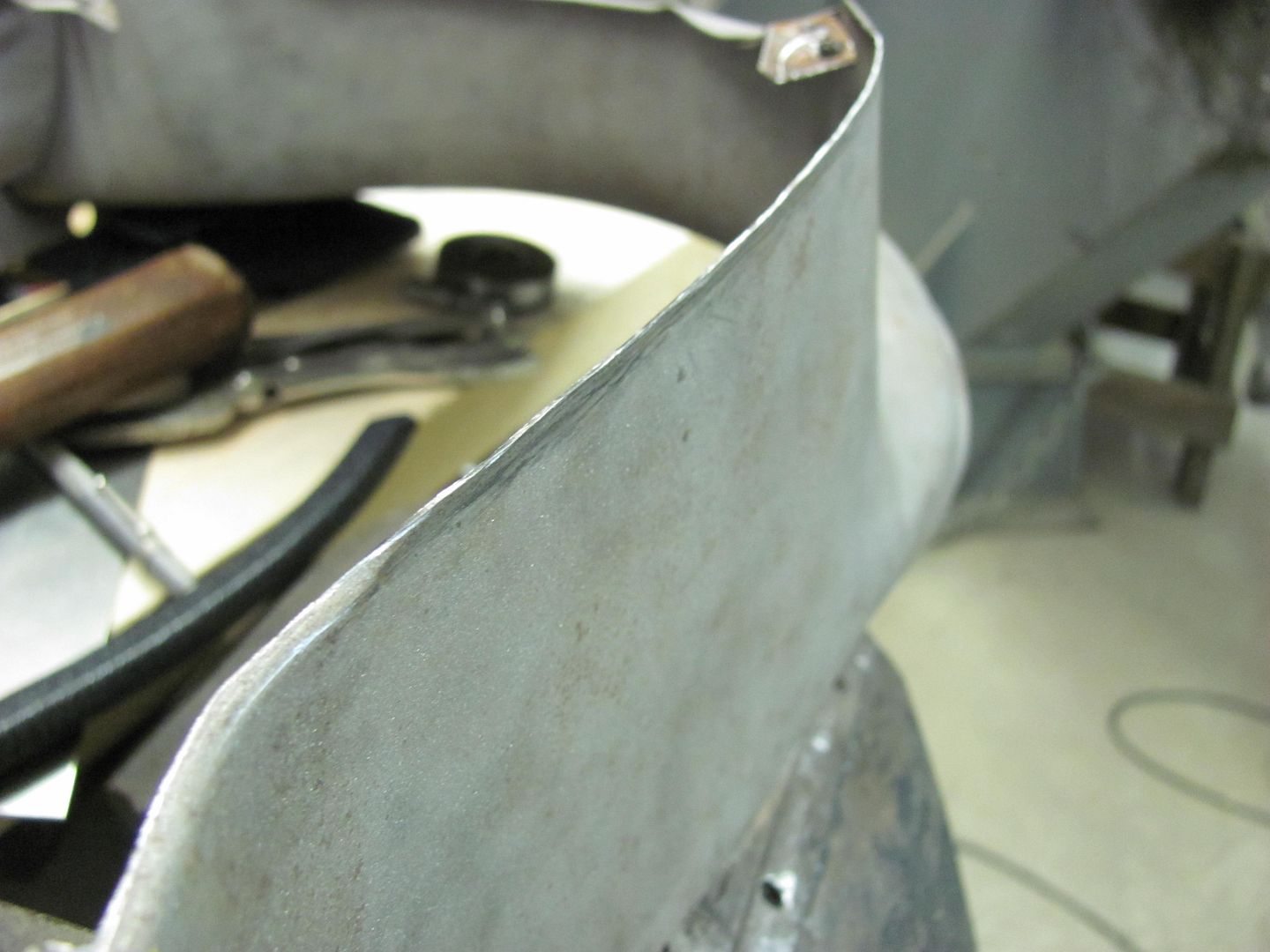
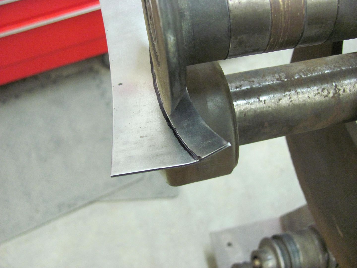
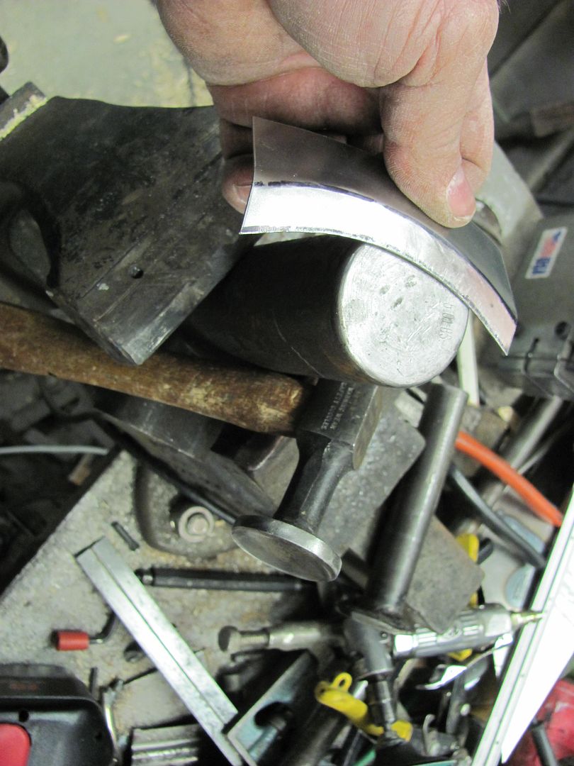
Yeah, I made some dies for it to do tighter curves.
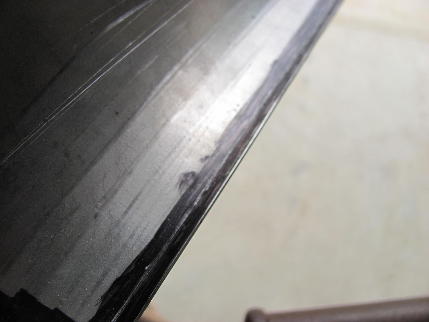
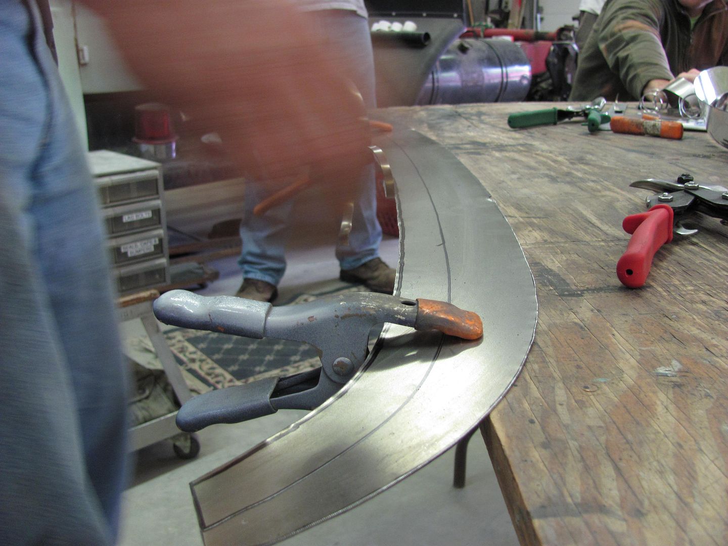
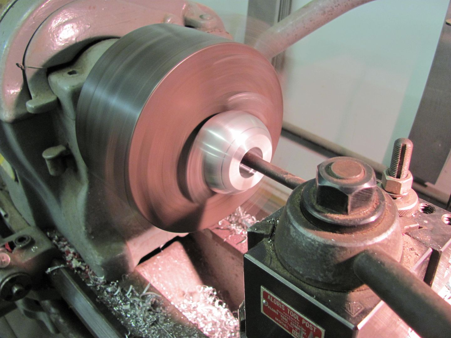
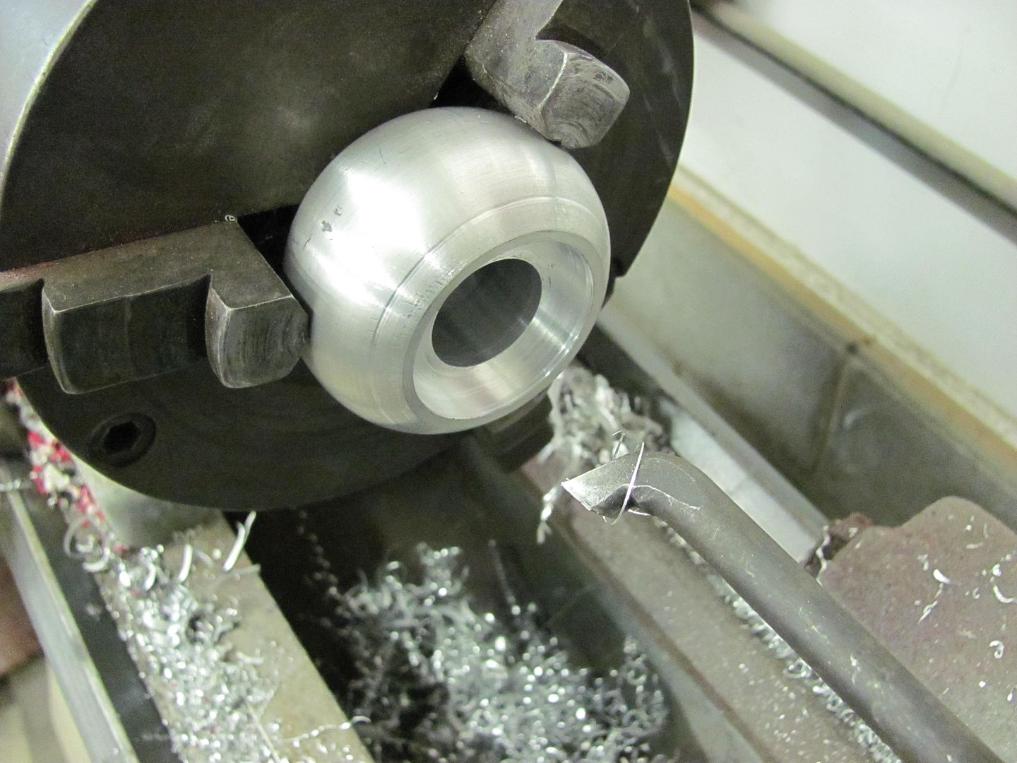
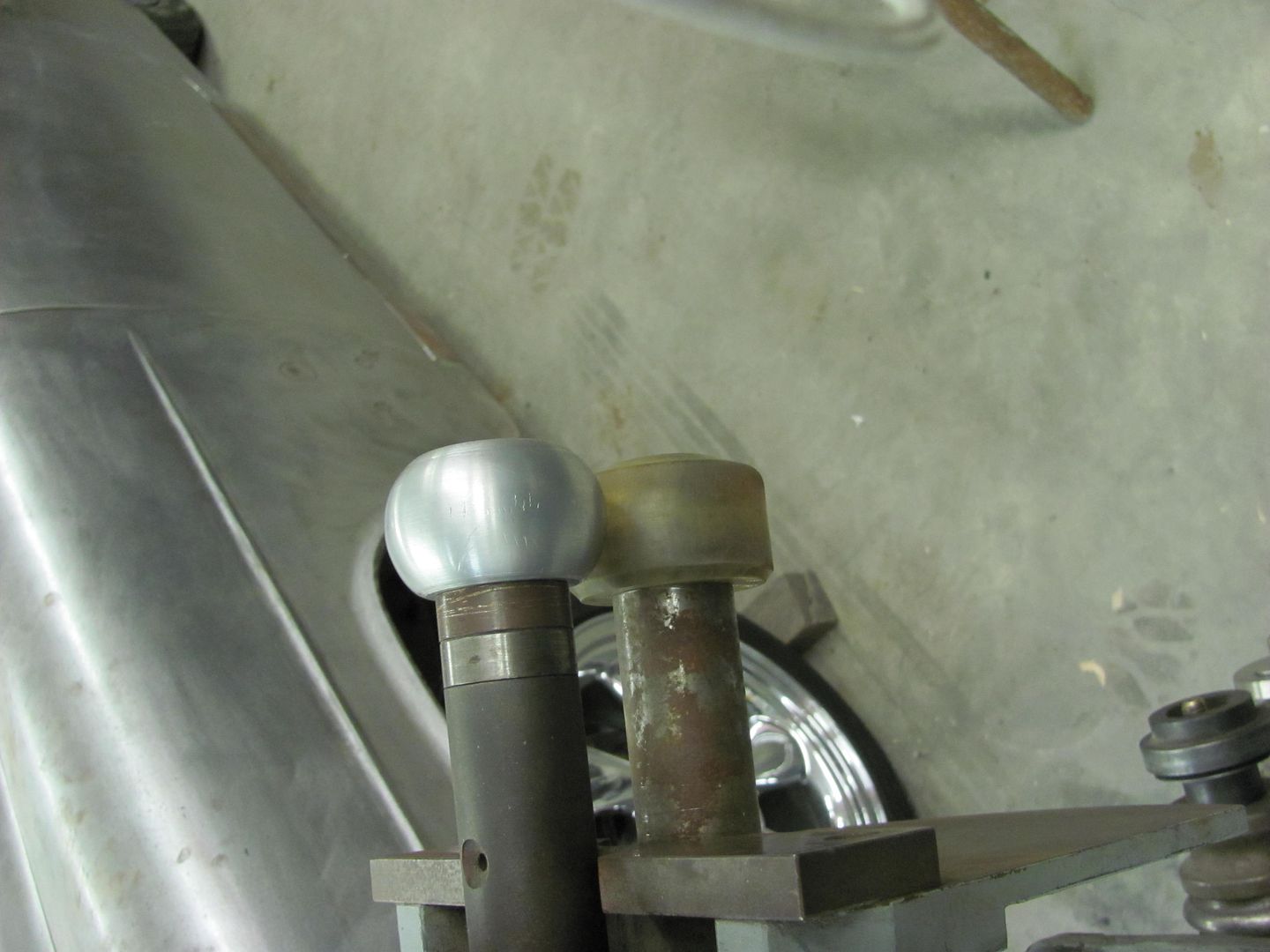
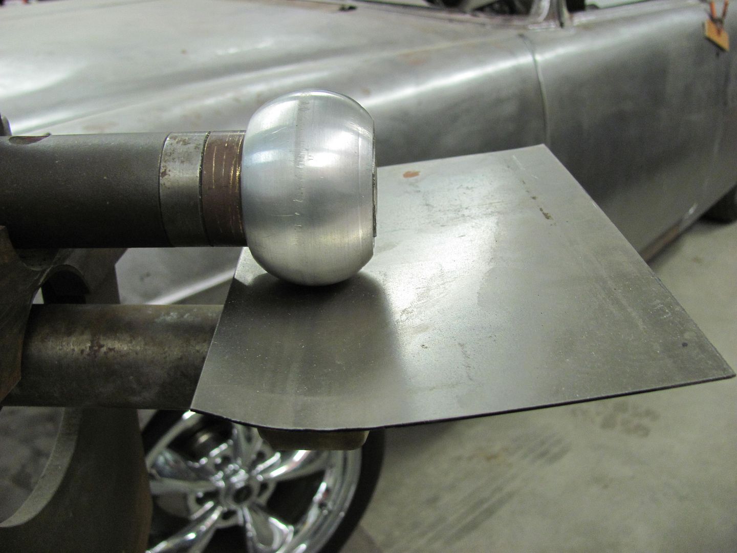
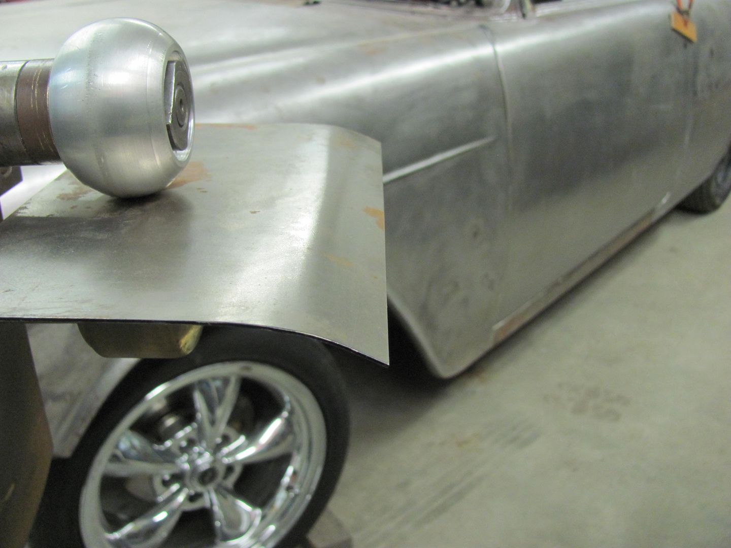
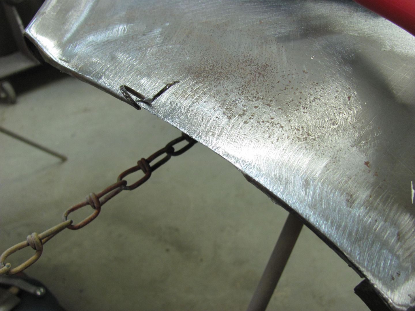
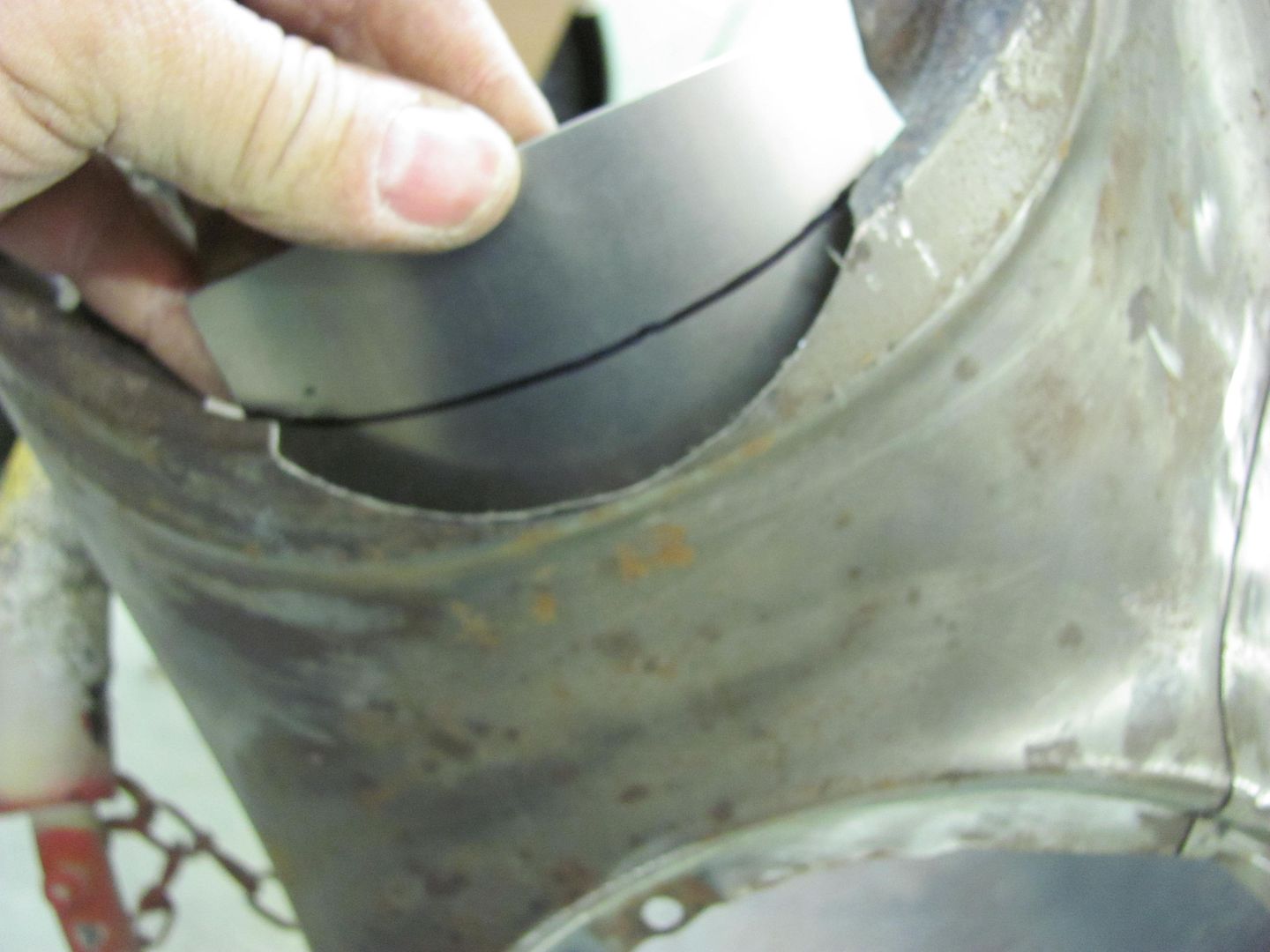
I used the english wheel to get the slight curve in it.
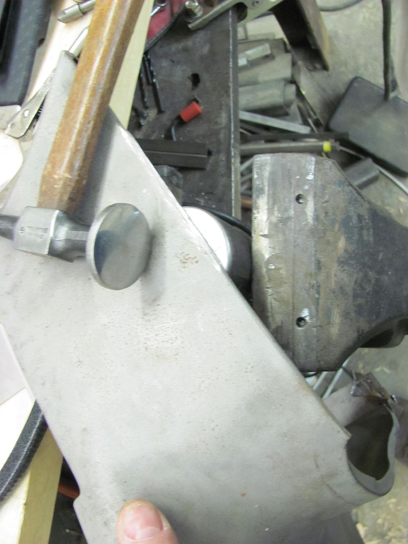
More amature hour... but i'm awful proud.


Here is a pig I made for my brother for his birthday.


I fell over and filled the kayak with water trying not to spill my beer......
Guess my next project will have to be a beer holder.


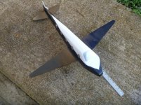
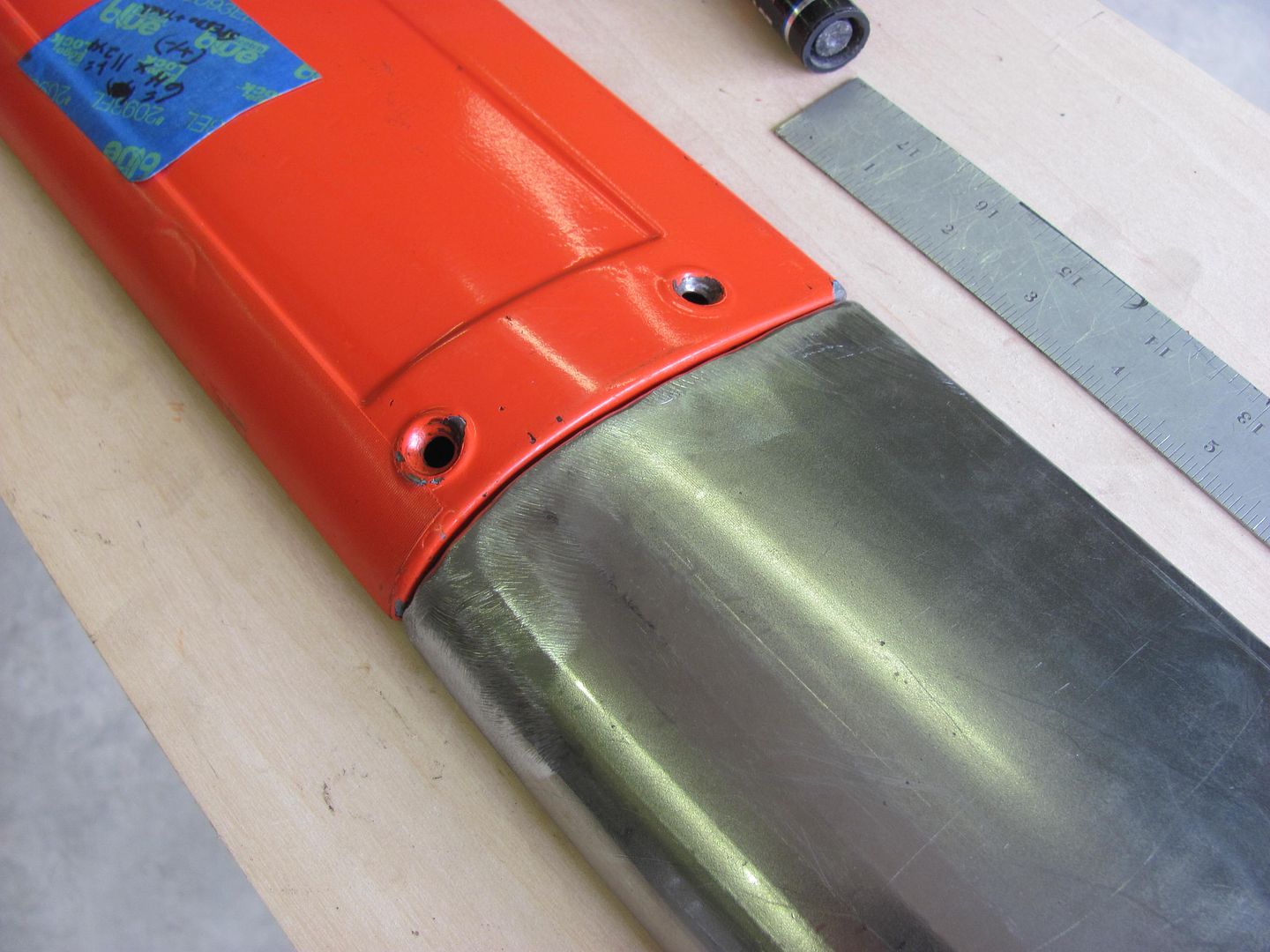
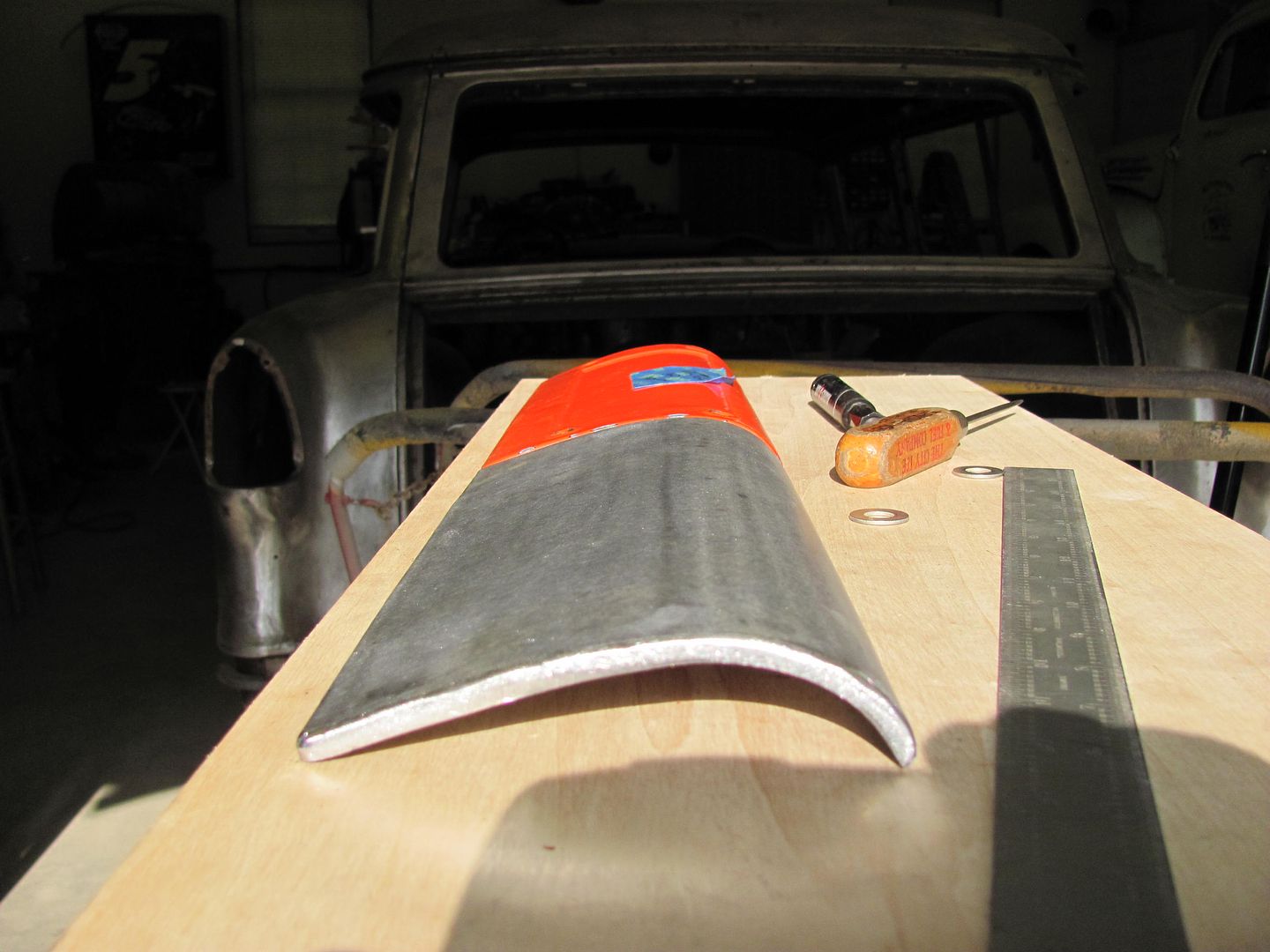
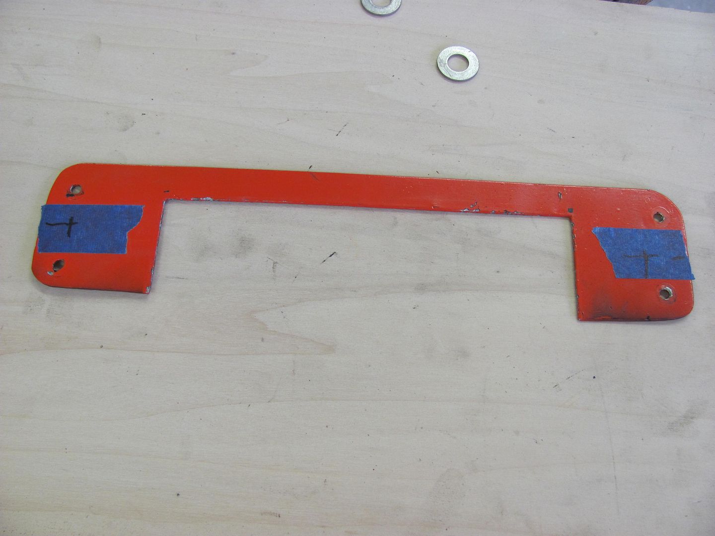
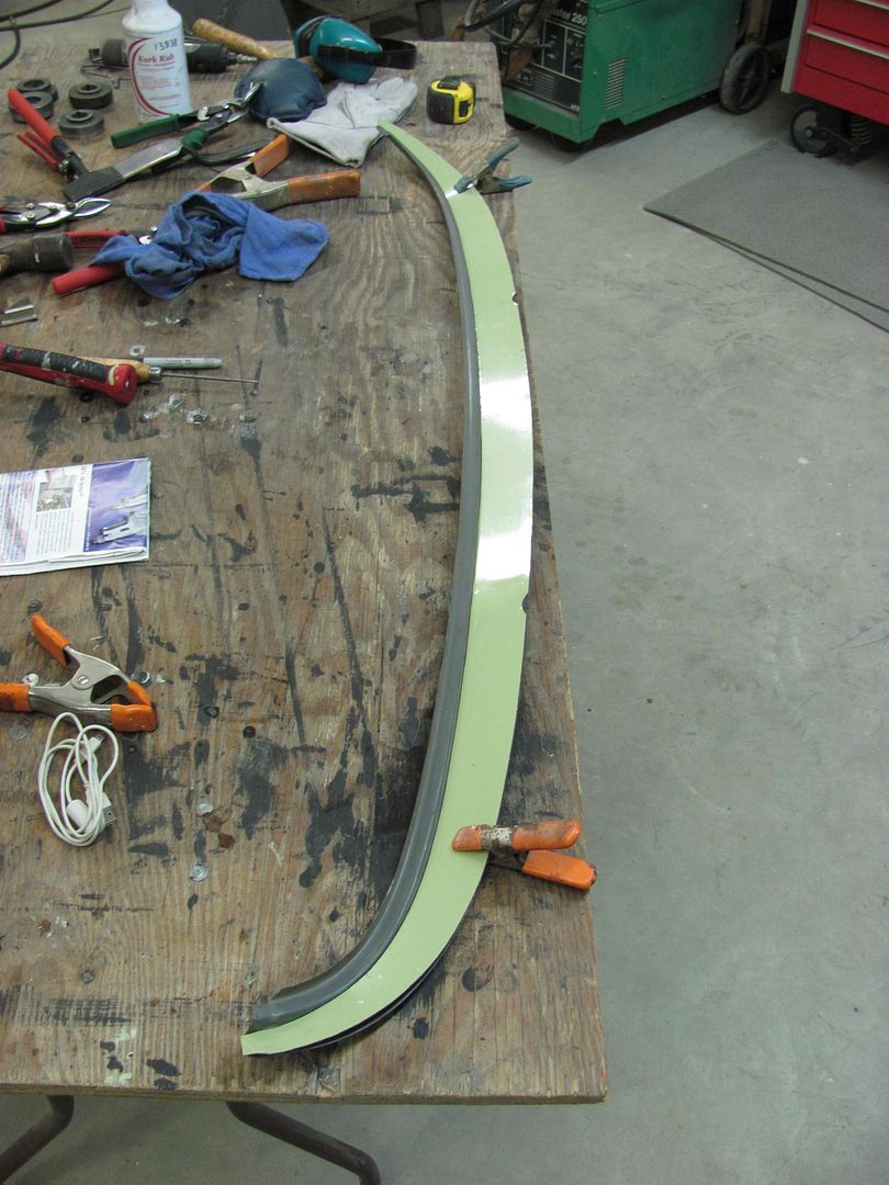
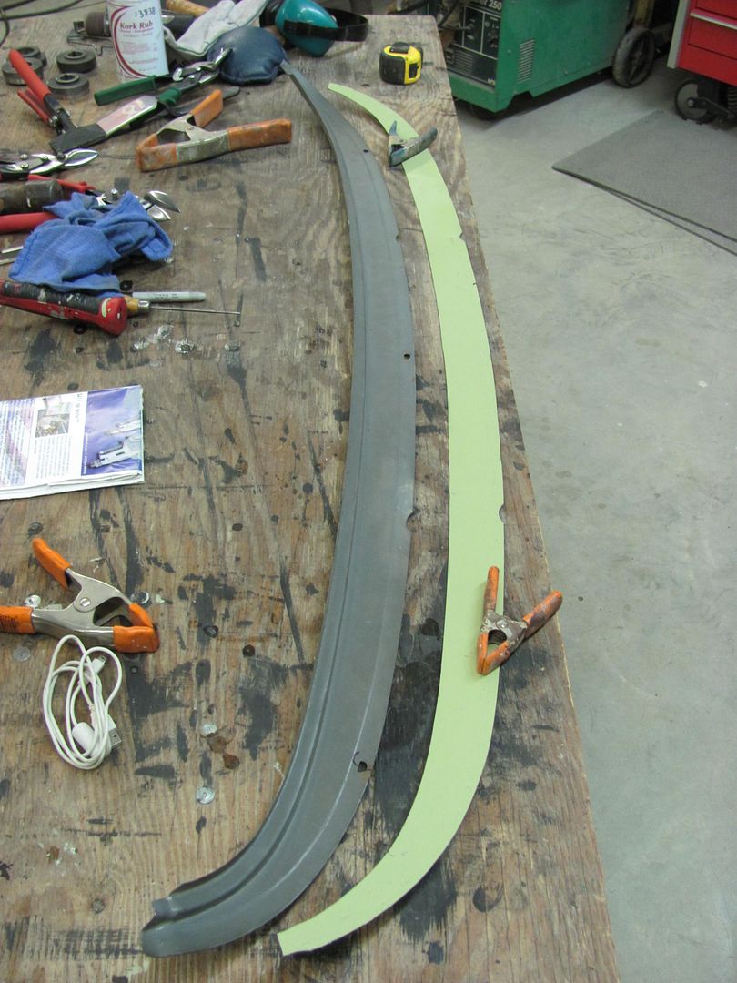
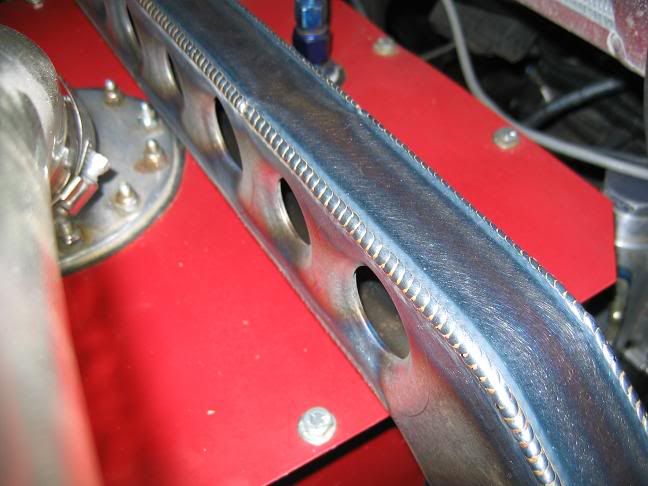
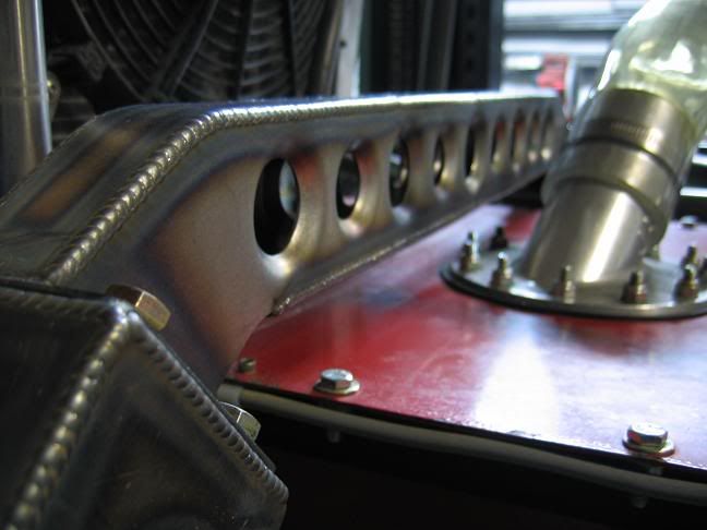
Wings custom made for some old Crosslé Formula Fords.

Funny how there just welded to the gear box cover.


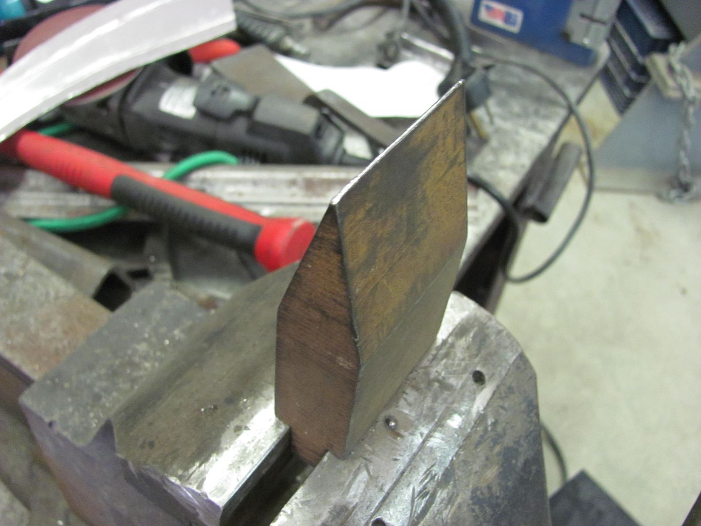
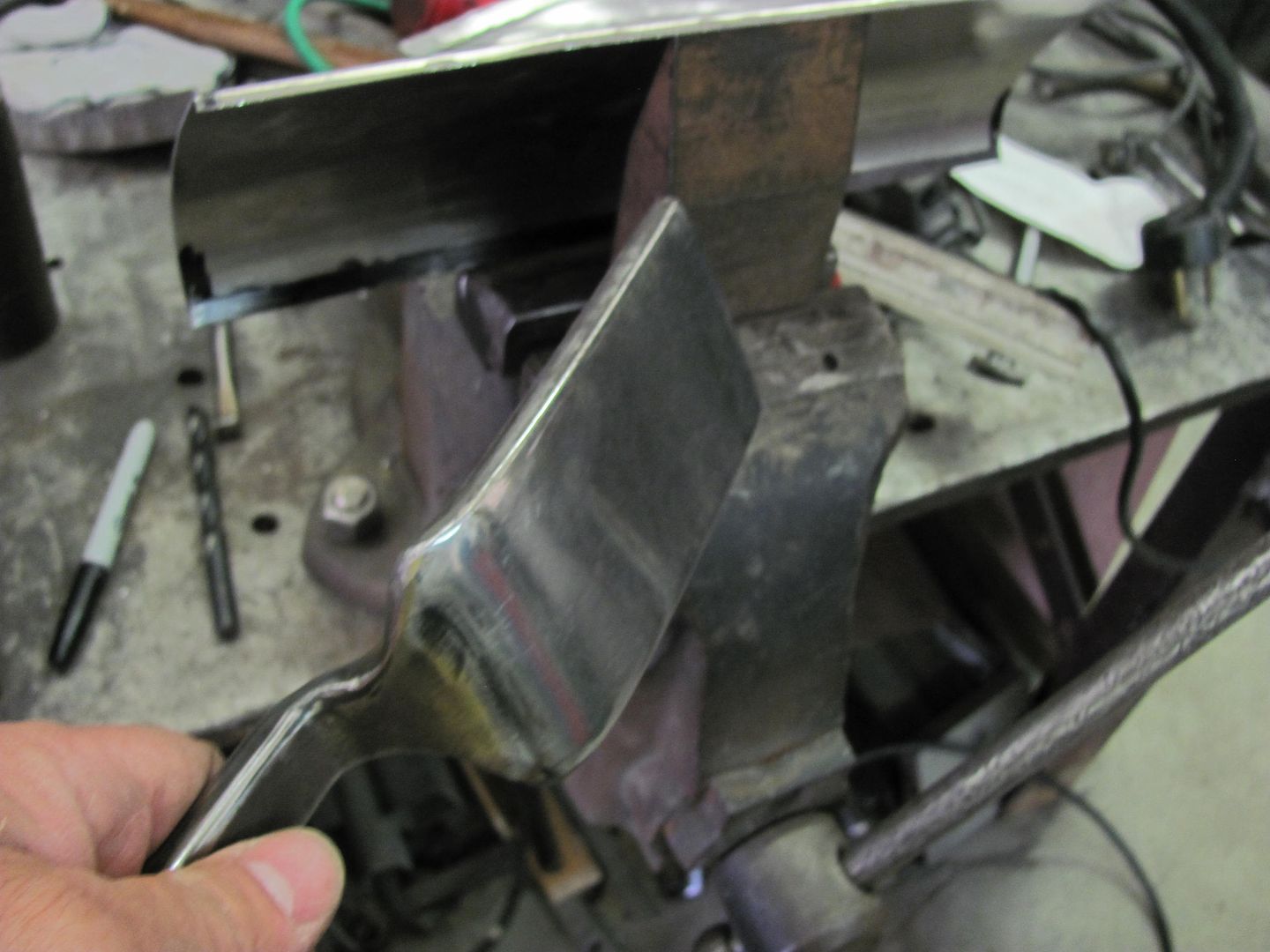
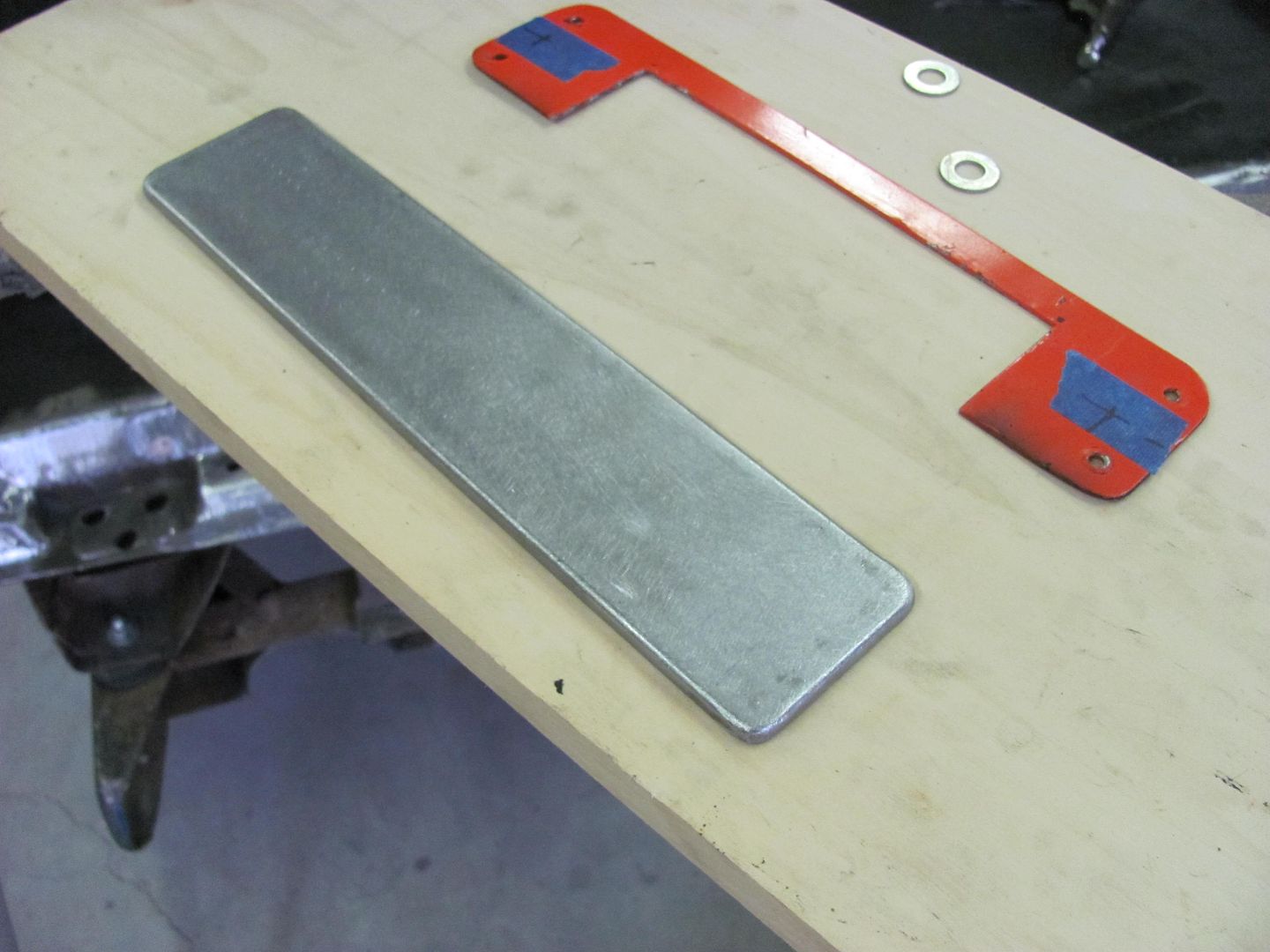
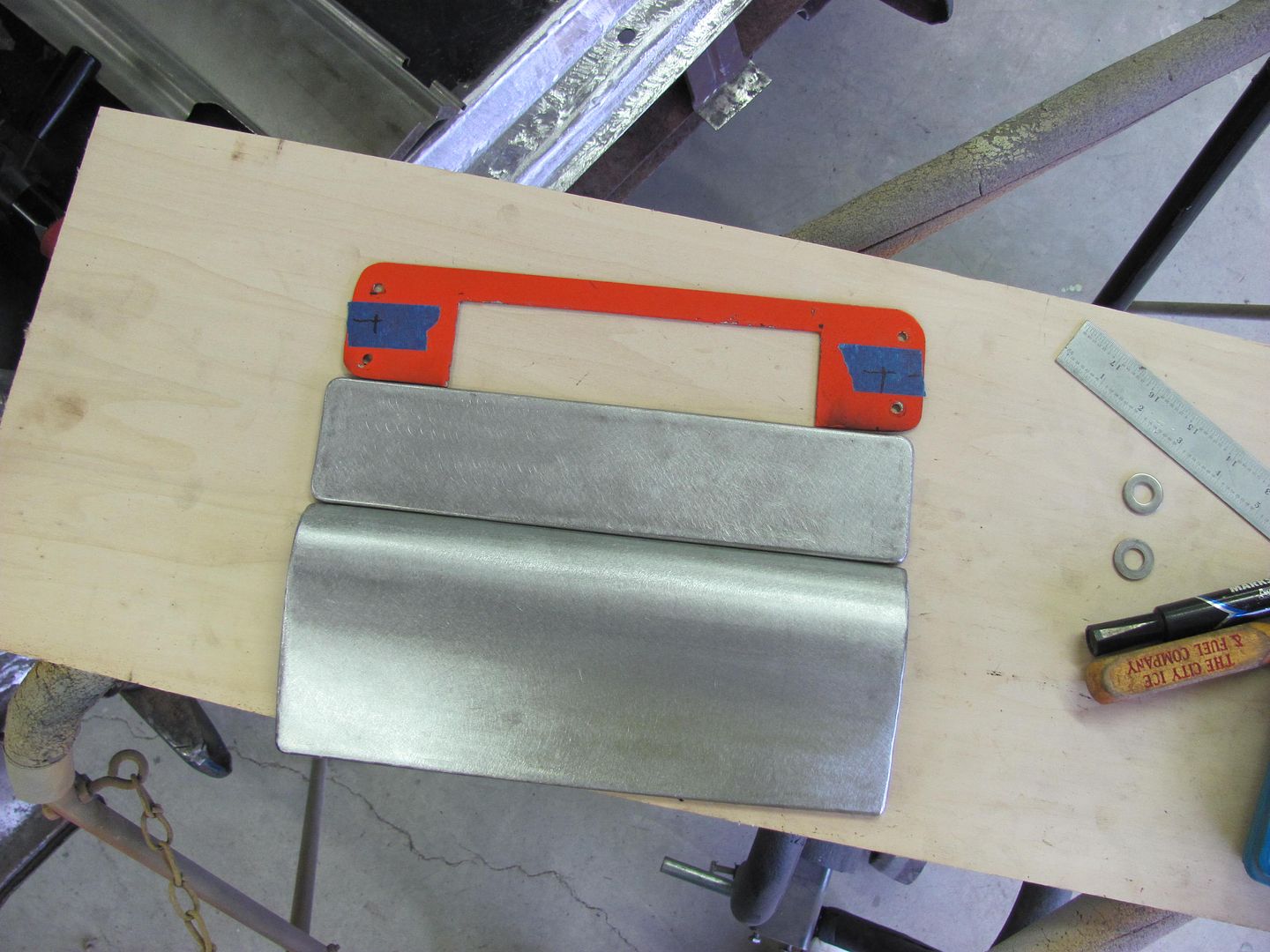
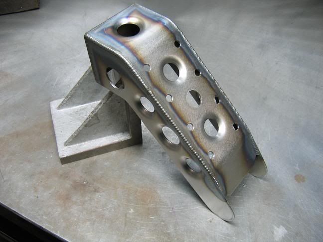
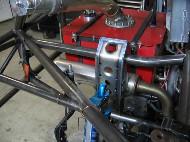
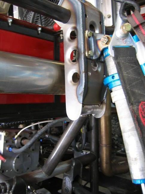
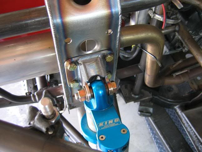
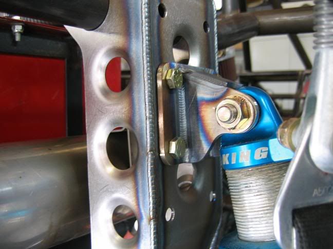
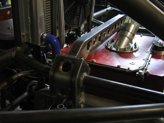
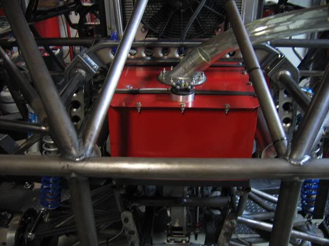
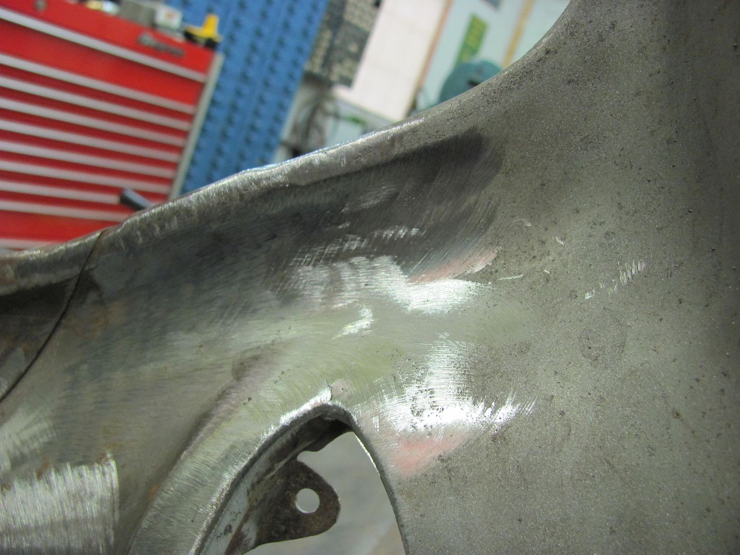
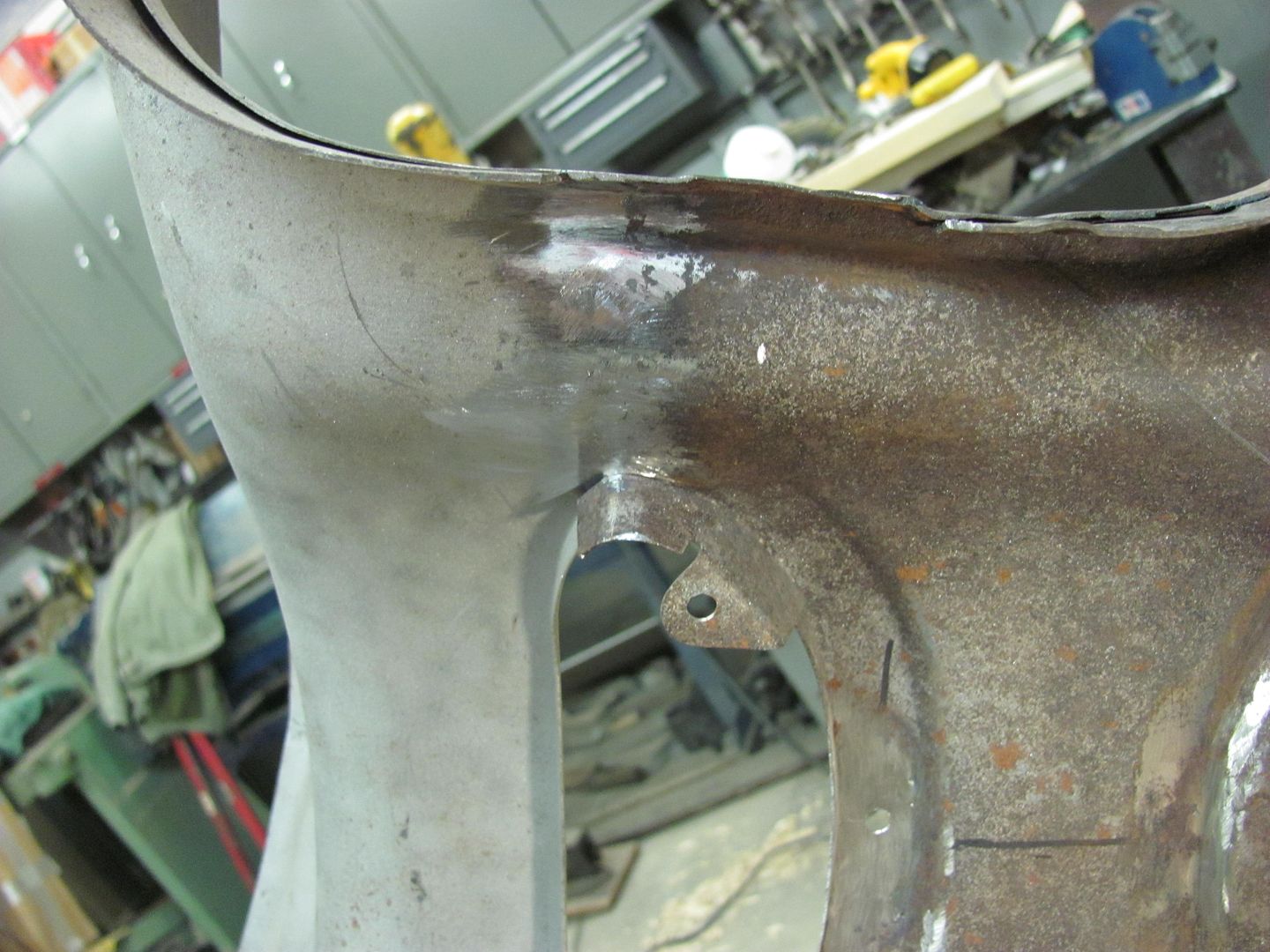
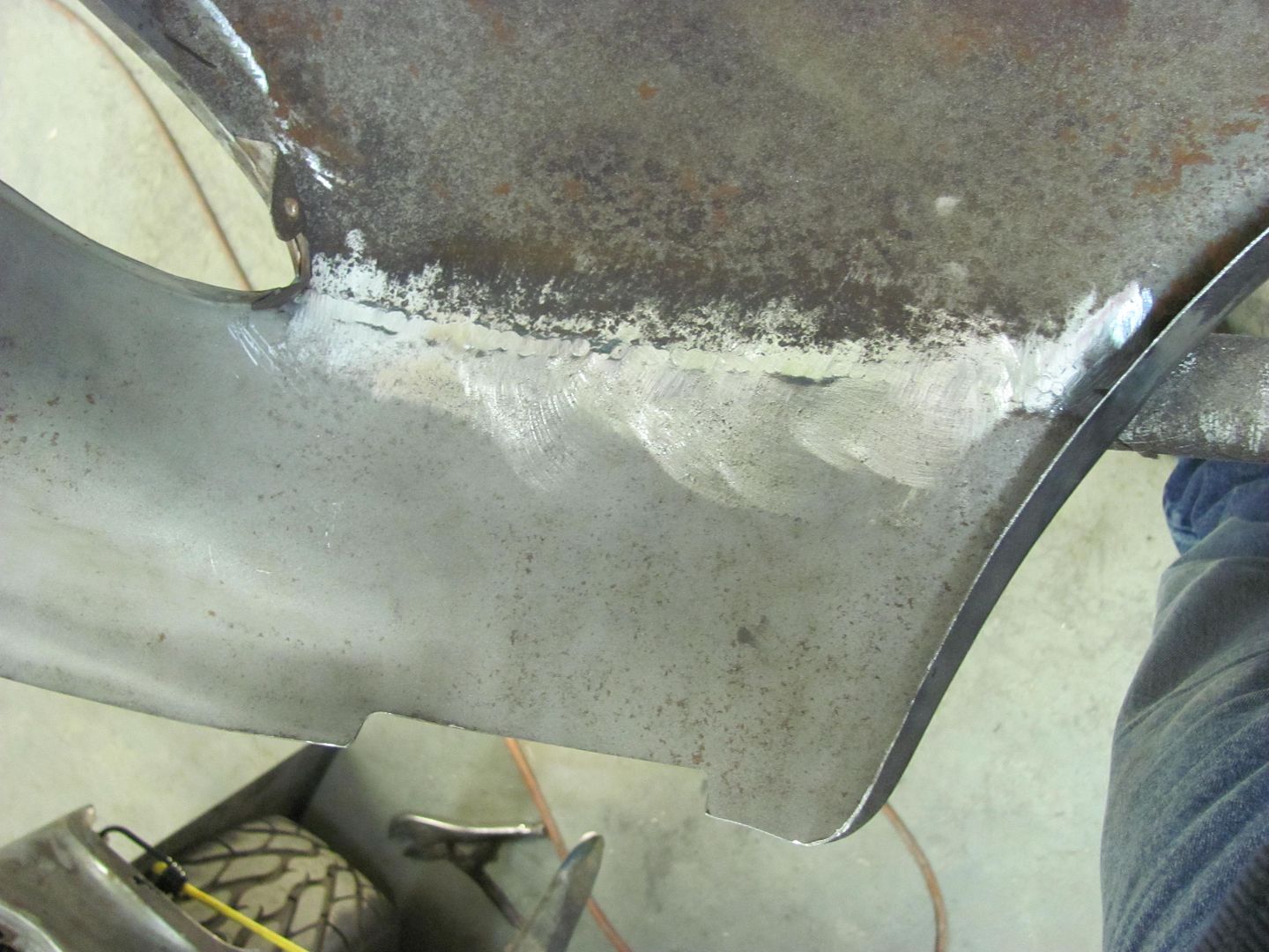
Here's some more work from the R1 Rhino.
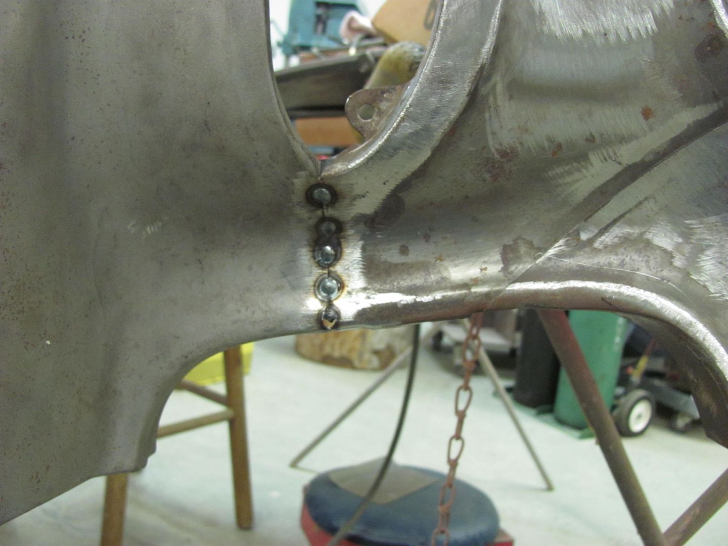
I had to redo the rear shock mounts since the guy that built the chassis didn't know how to.
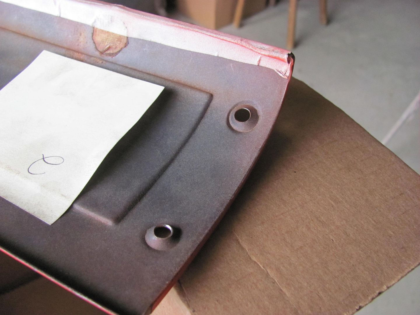
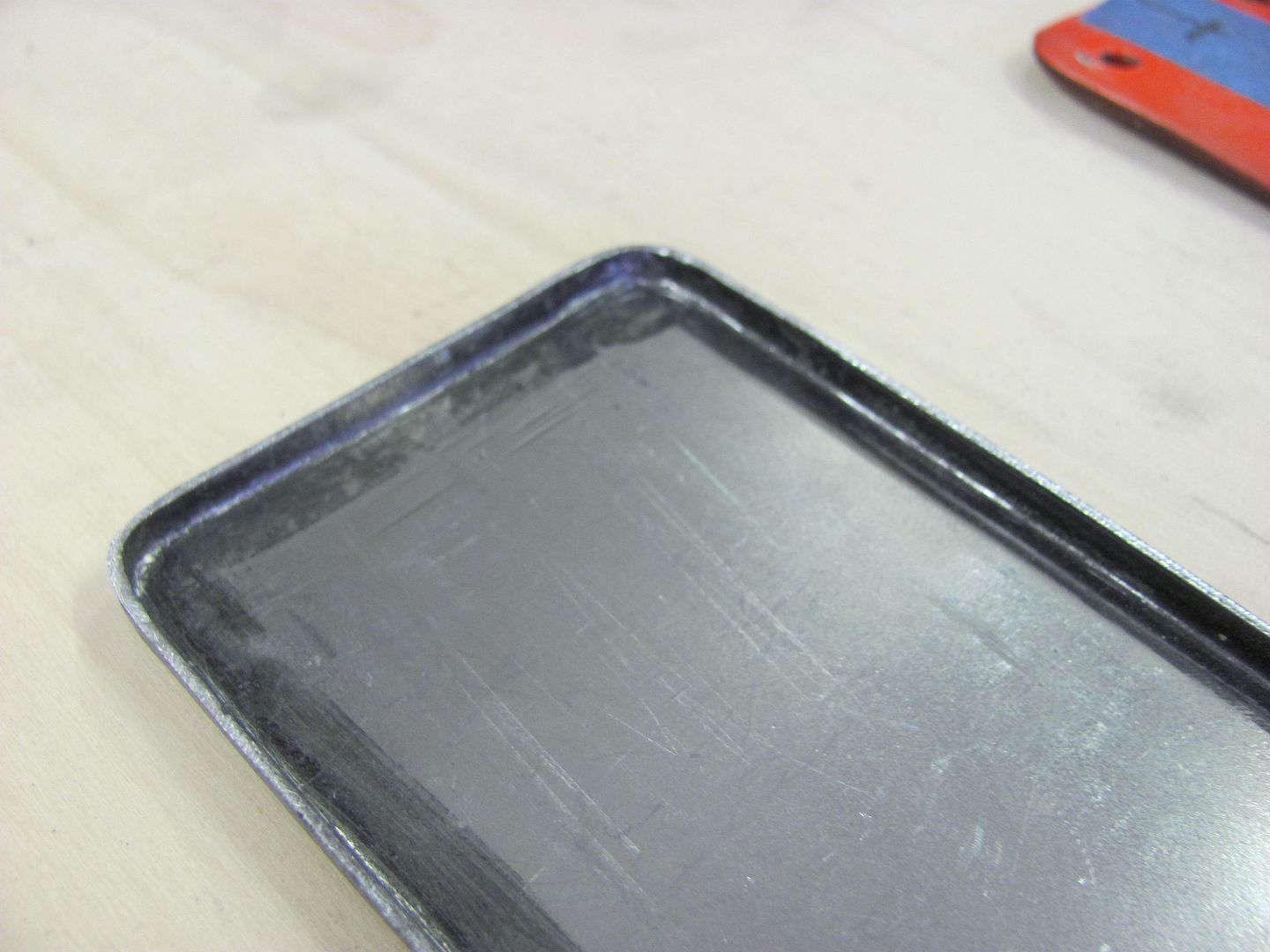
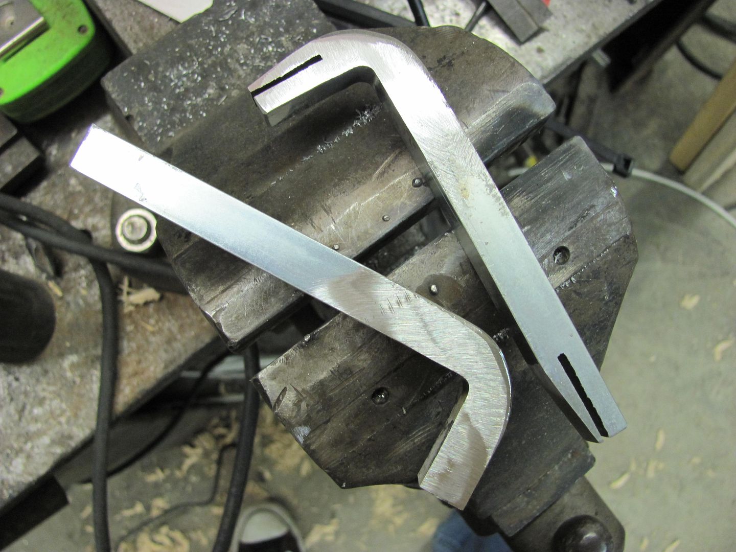
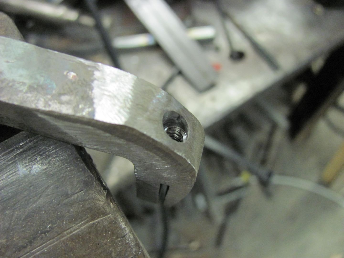
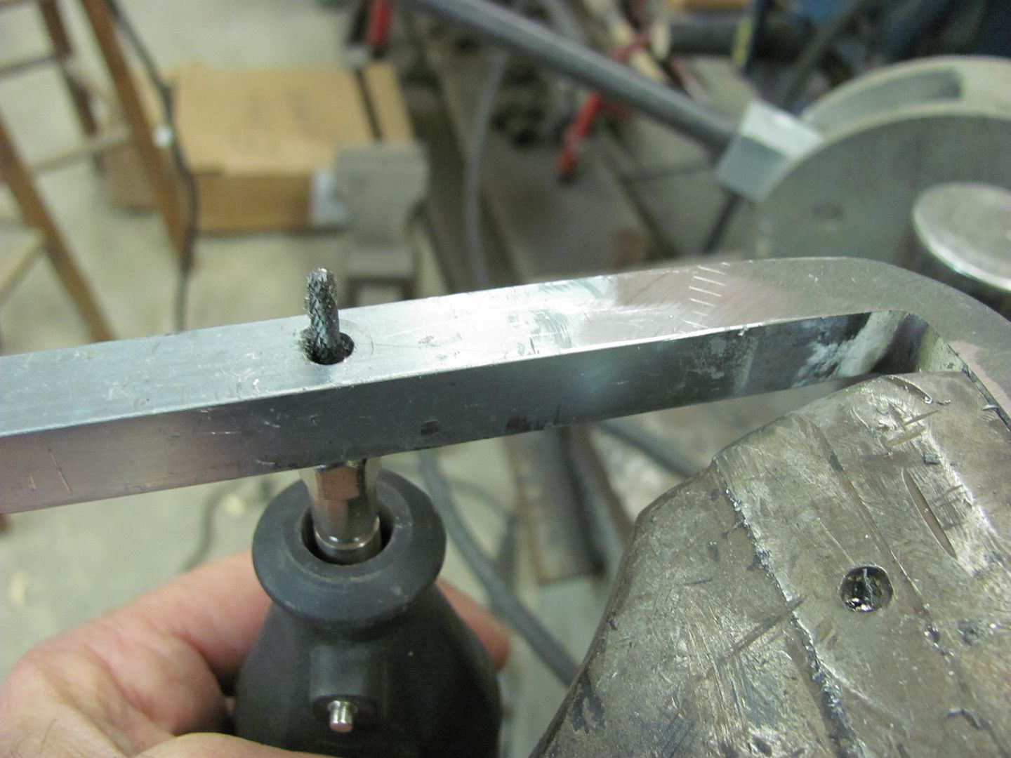
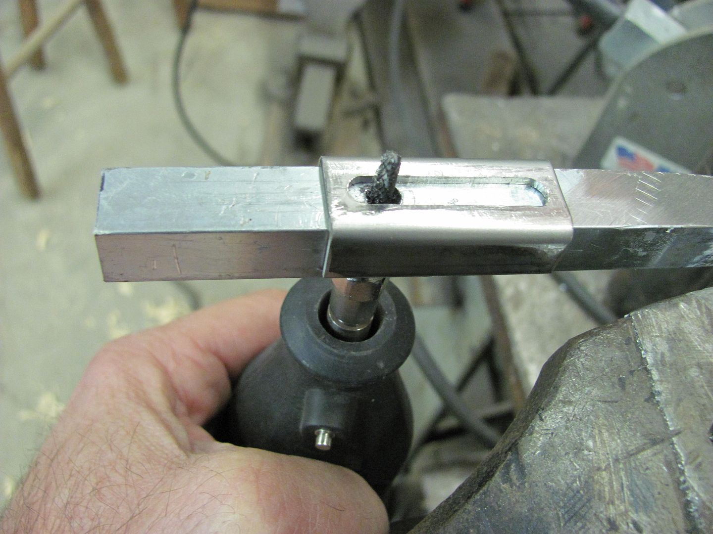
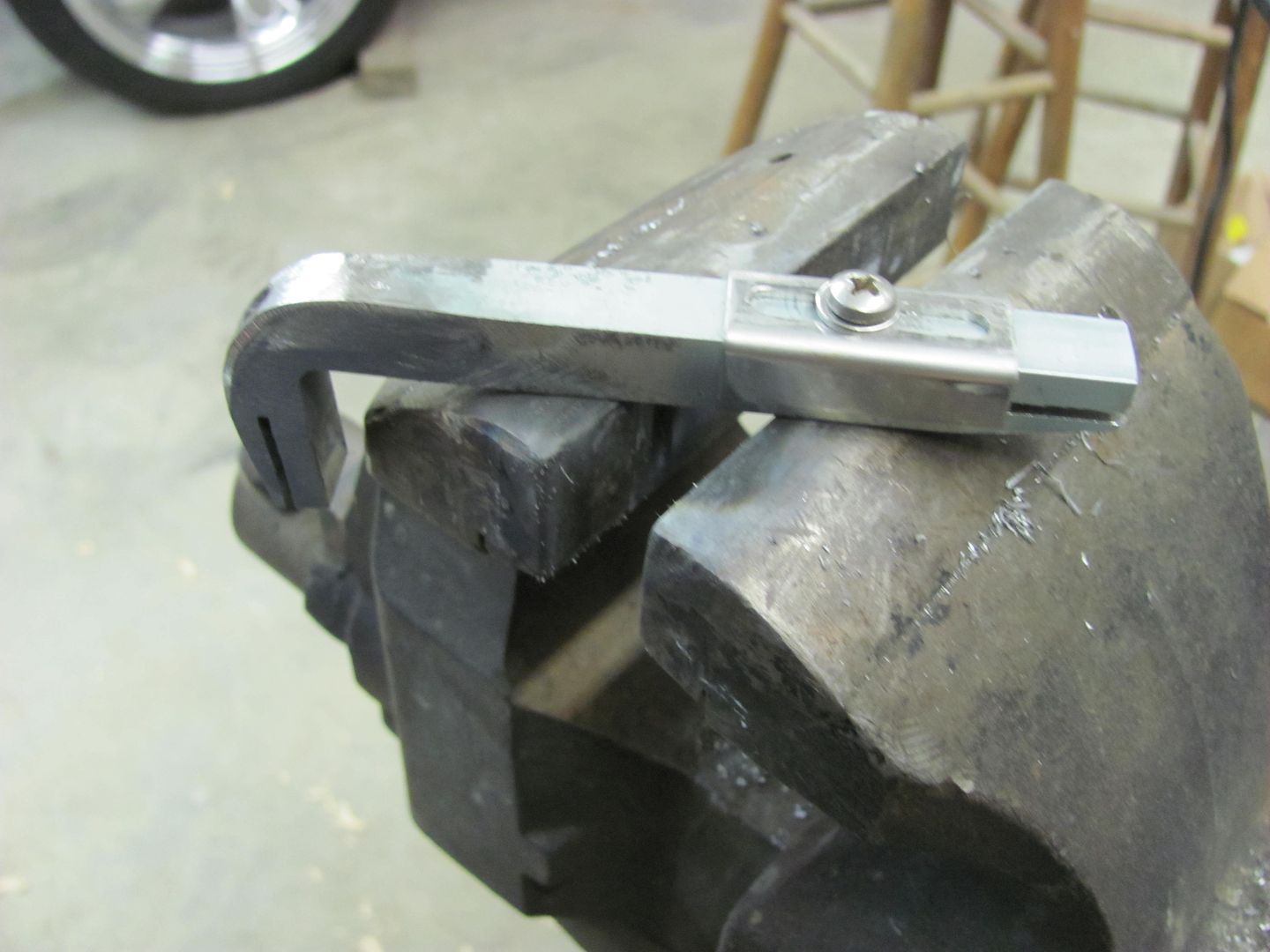
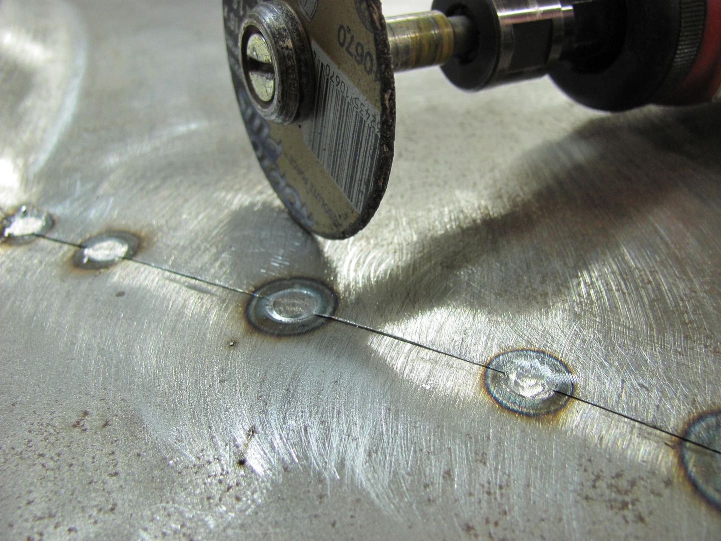
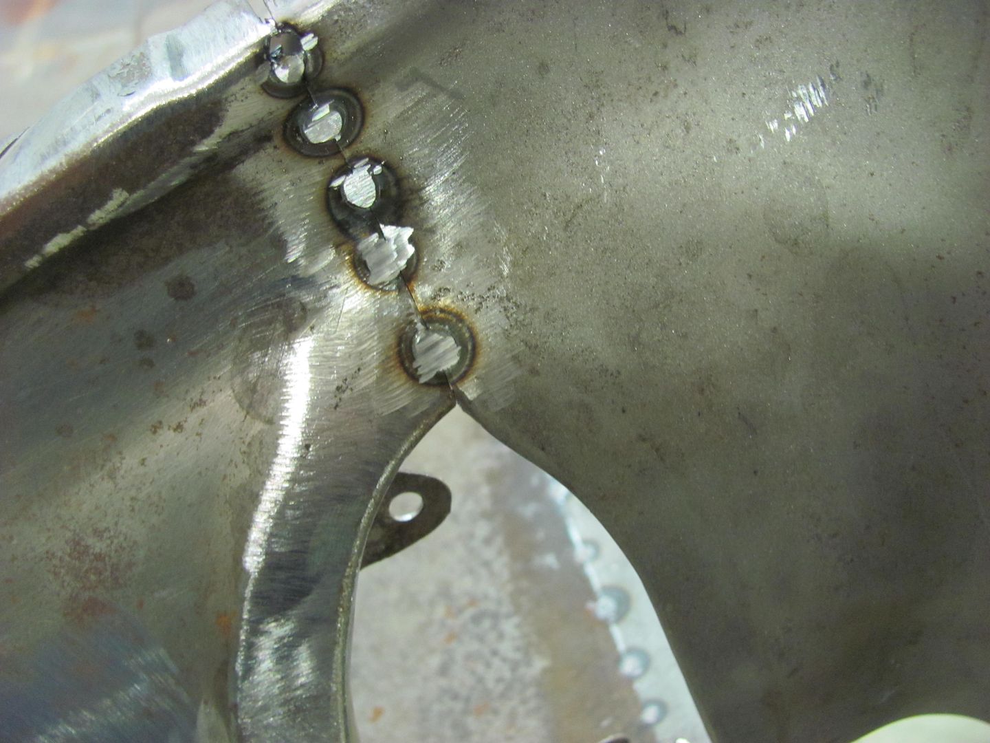
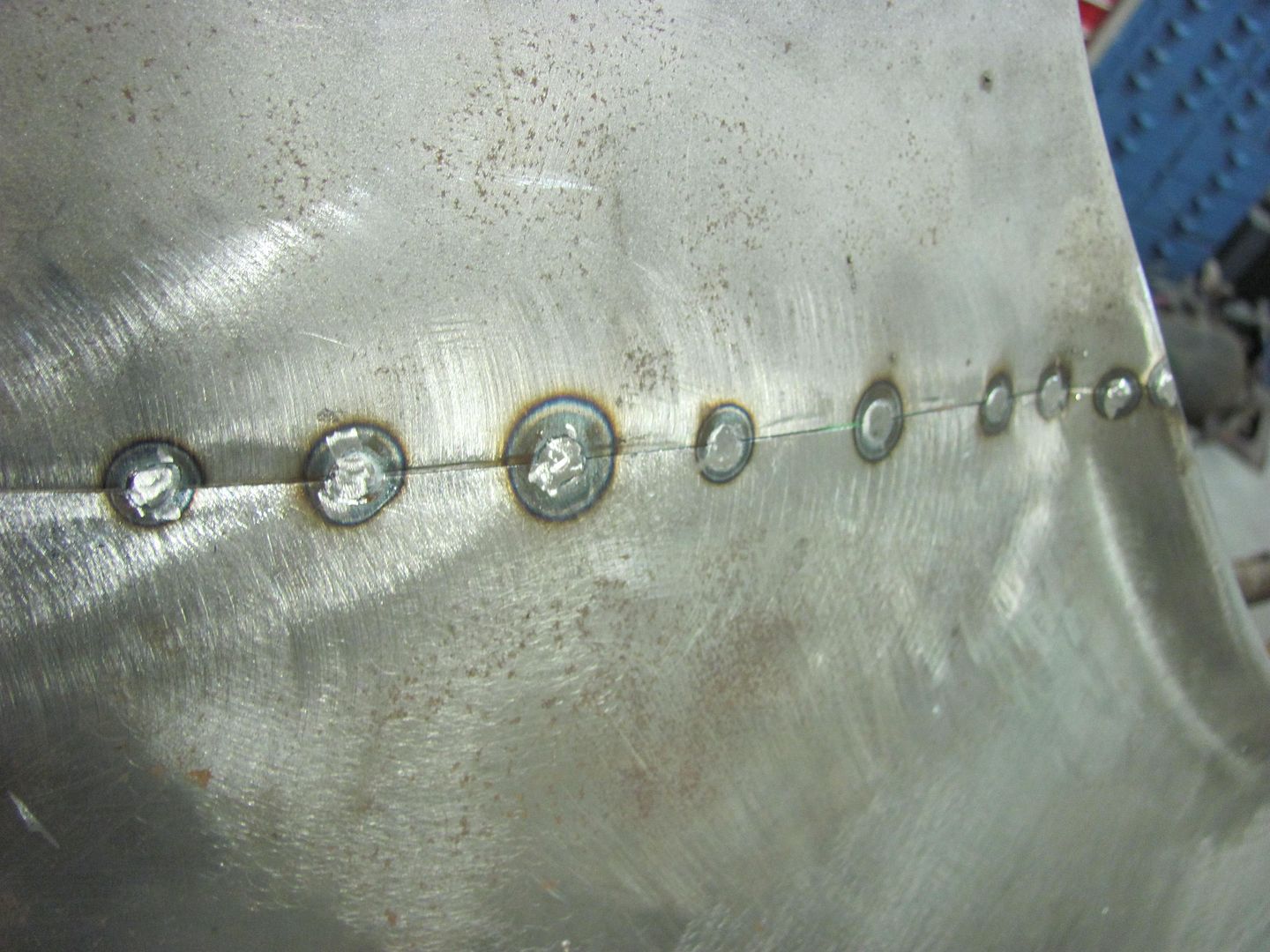
All pieces were either hand cut on my band saw or on my shear and dimpled using my JMR dimple dies. The shock tabs are 3/16" CRS and are TIG welded. The shock mounts and cross brace are all 11ga CRS are MIG welded.
The Shock mounts:
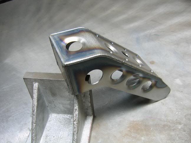
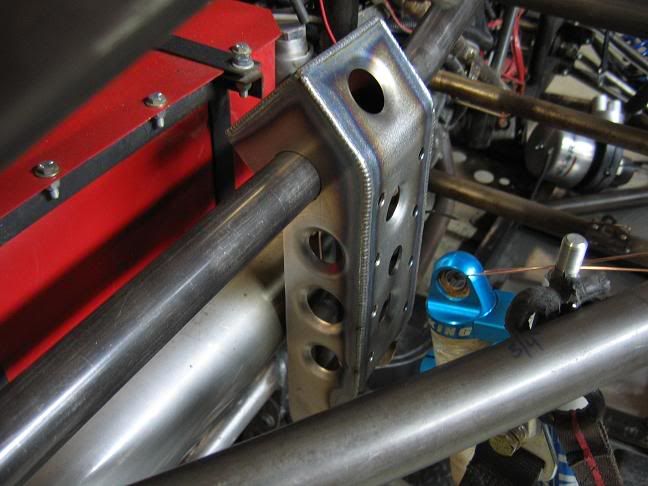
The Shock Tabs:
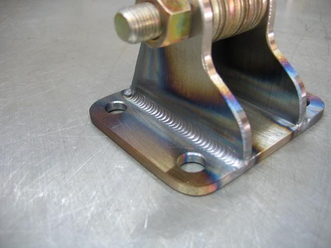
The Cross Brace:


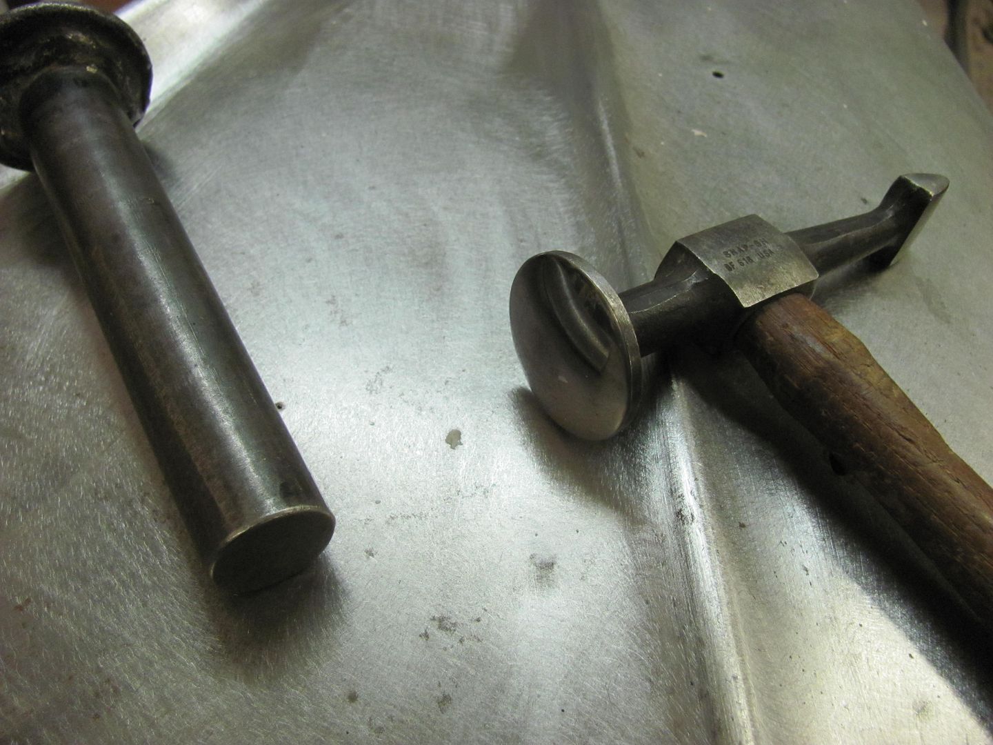


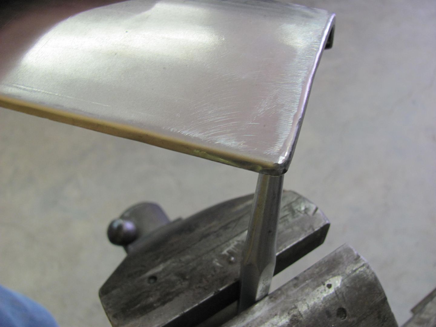
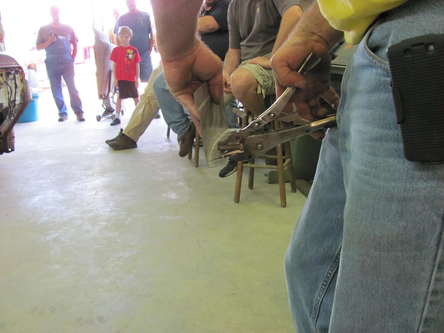
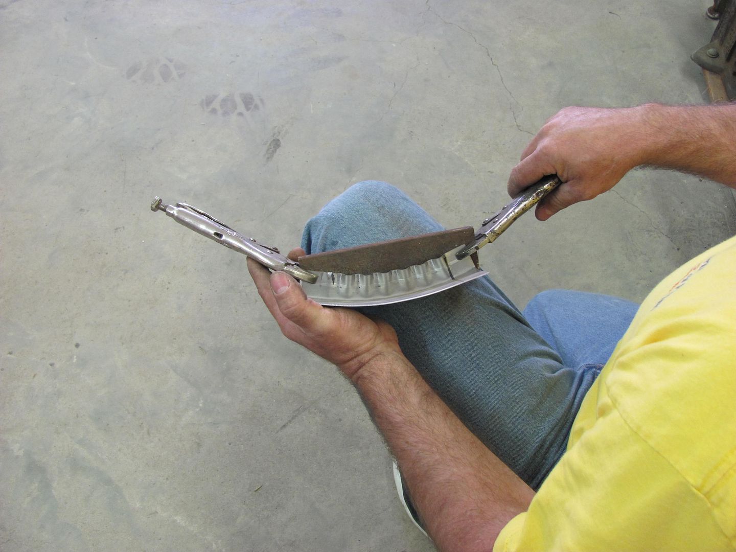
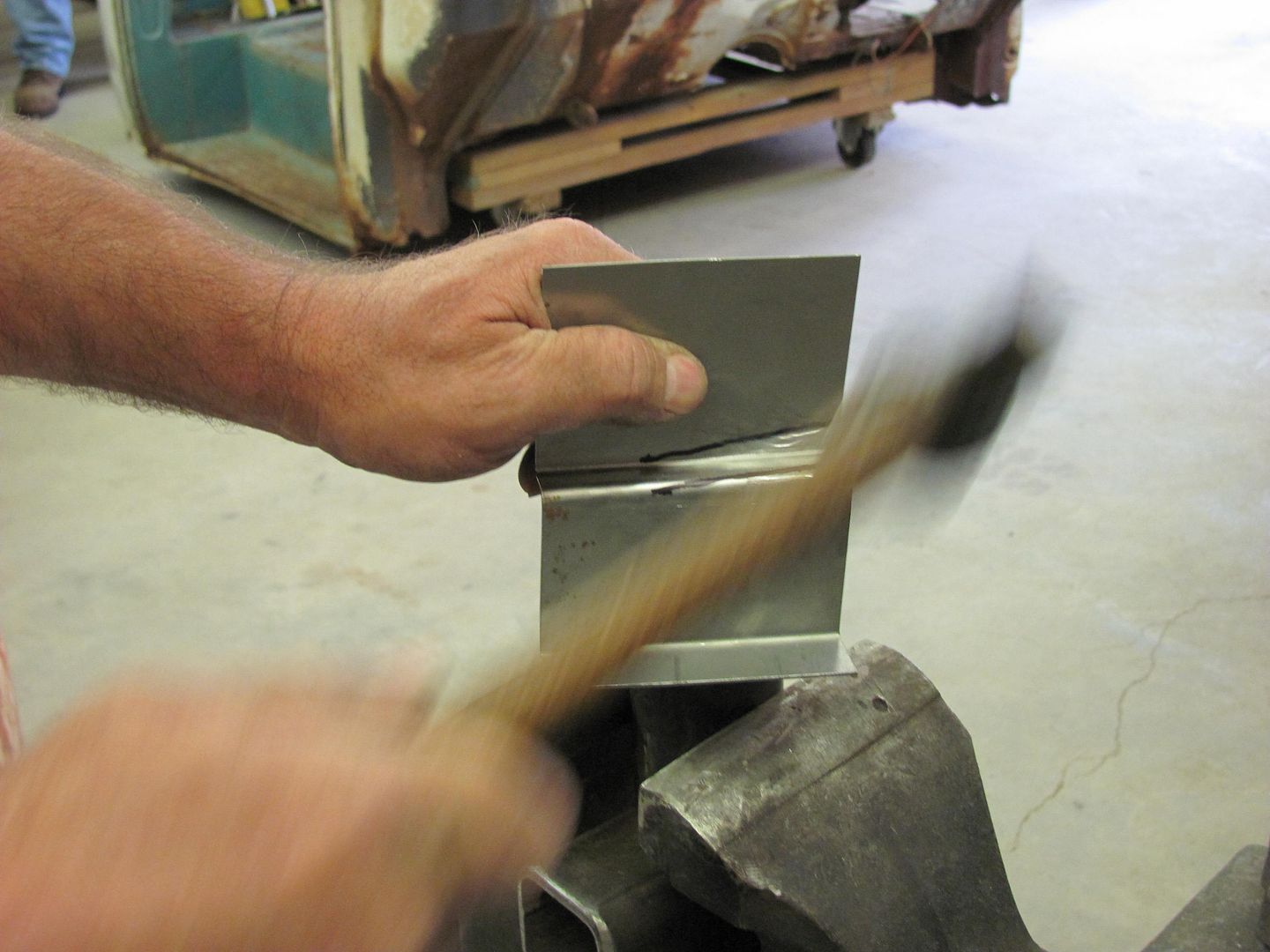
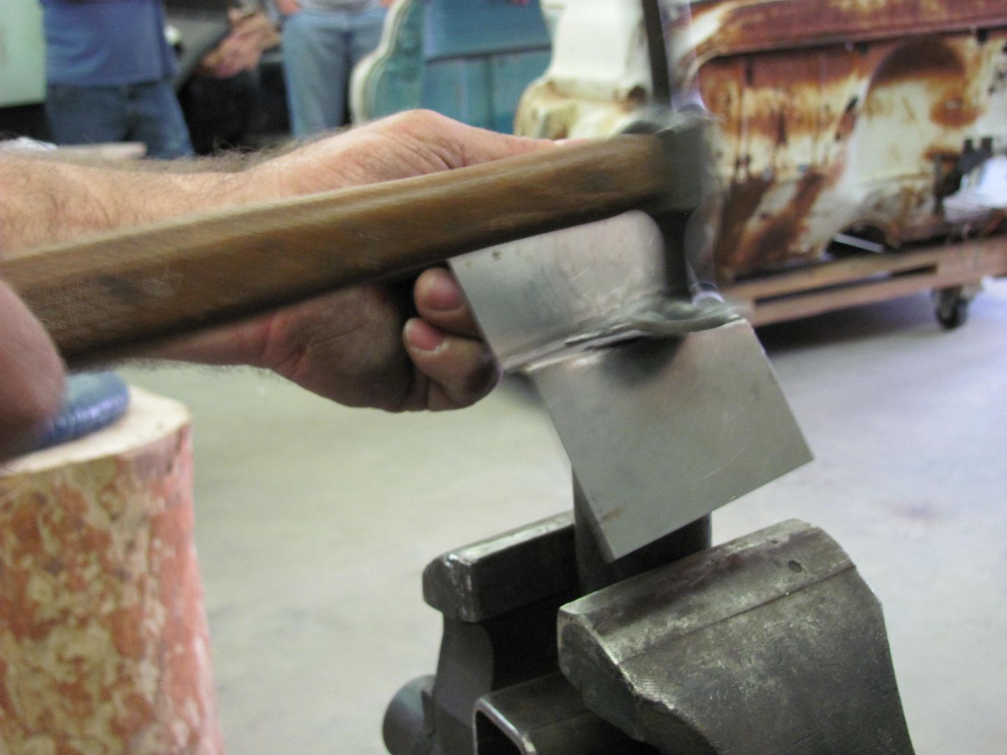
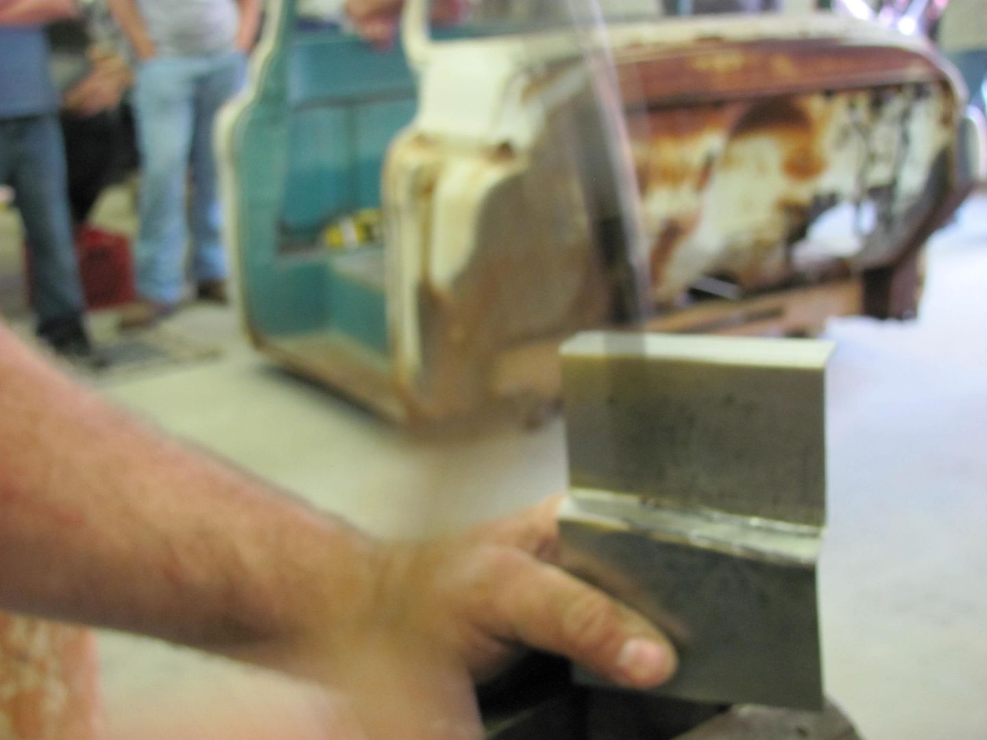
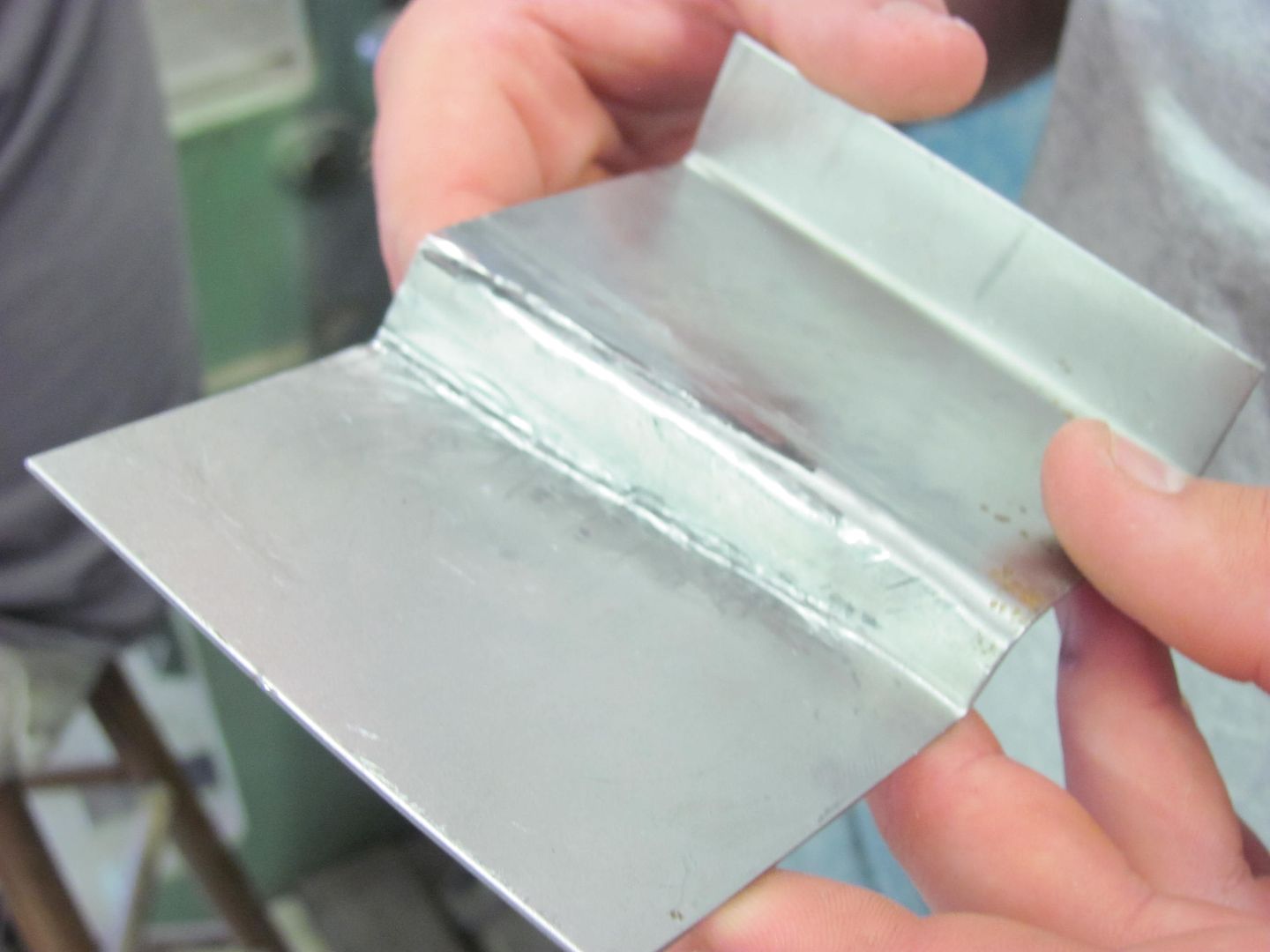
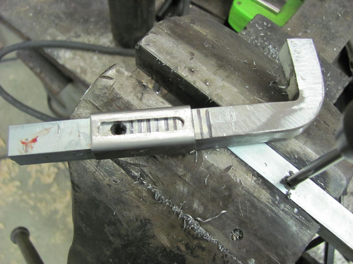
A picture is worth a thousand words.
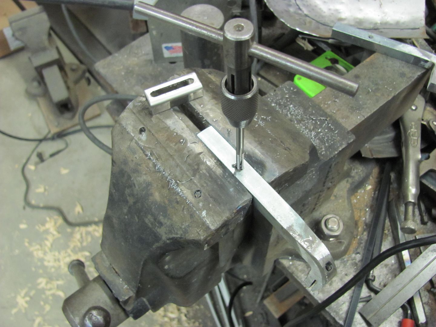
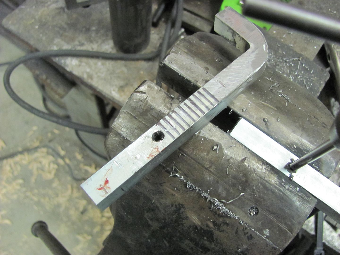
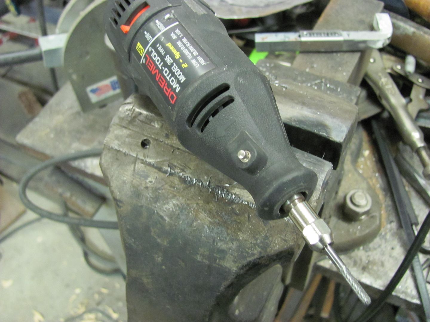
This is how I do it.


Ta da!

It can be done with hammer and dolley or back die. But that requires a lot of practice to get right.
Where your part will go also determines the method of dimpling.
What kind of press are you using?
Just a simple home made 10ton shop press.