To avoid these ads, REGISTER NOW!

Between 265 & 485 SQ/FT The 12-Gauge Garage

Workspaces sized between 265 and 485 squarefeet.

slik560

Well-known member
Joined
Oct 5, 2009
Messages
787
Location
Kansas, USA
I knew I should have paid more attention in science class. :dunno: Fascinating stuff. You may end up with a wing design to patent. ;)
 
Last edited:
To avoid these ads, REGISTER NOW!
OP
J

Jack Olsen

Super Moderator
Staff member
Joined
Mar 22, 2009
Messages
6,678
Location
Los Angeles
I'm going to try the big X, then. Drag is not a huge issue with this thing. But I'm assuming smaller is better. I picked up some 1/16" stainless cable with 500# break strength, and some 1/32" stainless cable with 150# break strength. Does anyone have an opinion on whether I could get away with the skinny 150# stuff?
 

Dan in Pasadena

Well-known member
Joined
Feb 18, 2009
Messages
13,139
Location
Pasadena, CA
...... it breaks up the von Karmann vortex shedding to reduce vibration....

Ya, und zee von Karmann vortex ve'll getchoo und de end!

Sorry, I just couldn't help being a smart a$$. Sometimes you've just gotta go with your strengths!:lol:

Very nice work Jack. But you always do nice stuff in that garage. One of these days I need to stop by and get an idiot's guide lesson from you on your lighting and motion activator wiring. I've gone back and read it & read it and I'm a hardhead I guess.
 
Last edited:

jrod60

Well-known member
Joined
Apr 11, 2006
Messages
75
Location
Katy TX
I'm going to try the big X, then. Drag is not a huge issue with this thing. But I'm assuming smaller is better. I picked up some 1/16" stainless cable with 500# break strength, and some 1/32" stainless cable with 150# break strength. Does anyone have an opinion on whether I could get away with the skinny 150# stuff?


Can you determine from your ride height data how much downforce you're getting currently? Spring rate vs height delta or something like that? I would think the lateral loading on the uprights is similar, but I long ago forgot anything I may have picked up in statics and dynamics class....
 
OP
J

Jack Olsen

Super Moderator
Staff member
Joined
Mar 22, 2009
Messages
6,678
Location
Los Angeles
Ya, und zee von Karmann vortex ve'll getchoo und de end!

Sorry, I just couldn't help being a smart a$$. Sometimes you've just gotta go with your strengths!:lol:

Very nice work Jack. But you always do nice stuff in that garage. One of these days I need to stop by and get an idiot's guide lesson from you on your lighting and motion activator wiring. I've gone back and read it & read it and I'm a hardhead I guess.

You're always welcome, Dan. That said, my electrical work is really terrible. Or rather, I simply didn't get it done before I started and now am stuck with kind of a mess. But a line runs from the outlet to a motion detector, and then to the lights involved. I think there are four different 'zones' that come on as you walk through the place.

Can you determine from your ride height data how much downforce you're getting currently? Spring rate vs height delta or something like that? I would think the lateral loading on the uprights is similar, but I long ago forgot anything I may have picked up in statics and dynamics class....

Yes, pretty much. It's been a while, but I took a reading on the car at rest, and then added static weight in 50-pound increments to get a rough idea of what amount of weight produces what change in the ride height (both front and rear). The tendency of the suspension to 'stick,' makes this less than perfect -- but you give the car a little jostle and hope it settles consistently. Then I could compare those numbers to the car runningr at speed with no aero on it (where it generates quite a bit of lift, unfortunately), and with the different wing settings (which offset that lift, to lesser and greater amounts). My memory is not great, but I think the thing was not too far down from the perfect-world numbers from its airfoil.

More important for me is the relative differences. I simply want to get the most I can out of the wing -- and also the front splitter. So I'll test it in each position, and then look at the data and pick a 'best' setting. I remember in the previous set of tests there was a point where the wing was doing too much work and bringing the front end up -- a kind of cantilever effect. That led to some more work on the front end aero (I didn't expect it, but I learned that aero mods to the front produce improvements at both the front and rear axles of the car, whereas the wing only helps in the back).

I've gotten a lot of help and advice from guys who know much more than me. But part of the fun is being able to try stuff that's truly stupid. This front wing didn't help, since the low pressure area it was creating was above the hood of the car (and not the road surface). It actually pulled the gasket out from under the hood when I tested it.

Wing021160272182.jpg


:bounce:
 

Huxley

Well-known member
Joined
Mar 4, 2008
Messages
210
Location
Colorado
2010-porsche-911-gt3-cup-2-600x399.jpg


You are definitely on the right track. That GT3 obviously has a couple of advantages on you: 'unlimited' budget, many man hours to devote to it, best materials available, manuf. facilities, etc.

A couple of things I noticed in the design above. It looks like it is tied into the wing on the lid. This essentially shortens the length of the uprights. Also, the uprights have that cool little twist built into them. This strengthens them against lateral forces. While that twist might not be easy to build into your version, a similar effect might be achieved by following the body line where it meets the quarter panels. What I am talking about is easily seen here...

supercupuprights.jpg


Your uprights do this but the angle doesn't appear as pronounced. If you can exaggerate the angle a bit more (while keeping the drag low), I think you will end up with a design that is much stronger. The cables can achieve similar results but they aren't as elegant.
 
Last edited by a moderator:
OP
J

Jack Olsen

Super Moderator
Staff member
Joined
Mar 22, 2009
Messages
6,678
Location
Los Angeles
Yes -- they've utilized the ducktail spoiler to also support the uprights and wing. I really can't do this, since my uprights have to come off the car for most of my driving. There are aftermarket parts for my model that would accomplish the same thing, but I'd have to store both a wing and a decklid assembly instead of just the wing and uprights.

Working on the assumption that the airflow was parallel to the car, I've tried to keep the uprights straight. But the airflow probably comes up and wraps along the car. At least, that's what this graphic seems to suggest.

I'll take a look at mine and see if they could be shaped to follow the rear decklid edges.

911_airflow.jpg


Edit: I just found these wool tuft test images, which make it look like the airflow is spilling down laterally where the uprights would go.

Burzel+rear+quarter1316232497.jpg


Burzel+above1316232473.jpg


With+Spoiler31132571263.jpg


Here's one with no spoiler.

No+Spoiler31132571148.jpg


Maybe the spoiler changes the direction of the air over that part of the chassis.

- - -

I put in the wire X yesterday, and now I'm going to add one more piece to keep the uprights at a fixed distance from each other. I'm going to use a carbon fiber tube for it, down behind the ducktail (where it will be in turbulence, I'm assuming, with less of a drag penalty).
 
Last edited:

EdT

Well-known member
Joined
Sep 21, 2010
Messages
1,104
Location
North Georgia
Jack,
There is a company called Brunton's that specializes in streamlined flying wires for aircraft that need such things. Apparently each wire is custom made to length with threaded terminations and clevises on the ends. If you decide that you really needs that extra .2 MPH this would be a way. I suspect that, since it's a special airplane part, it's in another galaxy of cost even compared to race car parts, but it does exist. I also recall that some of the go faster sail boats used streamlined rigging wire. Possibly even MORE expensive than airplane stuff. Have fun!
 

Outlawmws

Well-known member
Joined
Aug 9, 2011
Messages
39,252
Location
The Badlands
I'm going to try the big X, then. Drag is not a huge issue with this thing. But I'm assuming smaller is better. I picked up some 1/16" stainless cable with 500# break strength, and some 1/32" stainless cable with 150# break strength. Does anyone have an opinion on whether I could get away with the skinny 150# stuff?

I think you are fine with the 150# stuff. it's there to keep the side load from collapsing the verticals past their own resistance, not take 100% of the load, but I would use a fender washer at the attach point on the outside, so the fastener does not get sucked through.

Also "tune" the wires to an equal tone so they have equal tension ("strum" each one)

Interesting point on the spiral wrap and the von Karmann vortex and reducing the flow turbulence, so I'll ask if the cable has a coating? if not it may act as it's own "spiral wrap" at that small size.

I don't think the tap at the size I mention d would flap, as it very short. we are talking less that 1/4" after wrapping around the wire.

but its an easy test" use tape on one and not the other and make a test drive adn then review the film clip which one is "humming"
 

Bob Heine

ALLIANCE MEMBER
Joined
Oct 24, 2009
Messages
10,706
Location
Boca Raton, Florida
I'm going to try the big X, then. Drag is not a huge issue with this thing. But I'm assuming smaller is better. I picked up some 1/16" stainless cable with 500# break strength, and some 1/32" stainless cable with 150# break strength. Does anyone have an opinion on whether I could get away with the skinny 150# stuff?
Jack,

This is not very scientific but it is based on personal experience.

My first artificial arm had 1/32" cable because I answered the question "What is your job?" with "I'm a technical writer." The cable snapped after a couple of days of shoveling dirt in my back yard. After the third snapped cable I took the arm to another prosthetist and answered the question with "I'm a ditch digger." He used 3/32" cable and in 40 years of use, I have never broken that cable, even when lifting cast iron big block heads out of my Corvette.

I would recommend using the 1/16" cable because almost any cable attachment is going to weaken the cable. Add vibration and the weakest point may hold significantly less than the cable's rating.
 

Dan in Pasadena

Well-known member
Joined
Feb 18, 2009
Messages
13,139
Location
Pasadena, CA
Thanks for the response on the lights Jack. Actually that one sentence kinda clarifies it some. I've wondered if I could scavenge the sensor off an old outdoor motion light I have (I'm cheap) then use multiple lights off it? And I WAS wondering if the motion sensor could work with std long fluorescents but now I pretty much want to use clip on lights as you have. A problem is it looks like I'm limited to compact fluorescents as incandescent bulbs are becoming scarce to find.
 

alpinewhite

Well-known member
Joined
Aug 4, 2012
Messages
1,315
Location
Orange County, California, USA
Thanks for the response on the lights Jack. Actually that one sentence kinda clarifies it some. I've wondered if I could scavenge the sensor off an old outdoor motion light I have (I'm cheap) then use multiple lights off it? And I WAS wondering if the motion sensor could work with std long fluorescents but now I pretty much want to use clip on lights as you have. A problem is it looks like I'm limited to compact fluorescents as incandescent bulbs are becoming scarce to find.
Not all of these sensors will work for CFLs, Dan. Some of the older ones are SCR-based (Silicon-Controlled Rectifier) and only work with incandescent lights. The SCR converts the signal to DC (direct current) and CFLs and regular fluorescent lights will burn out their ballasts when given DC. Some of the newer controllers, however, are Triac-based. Triacs can be used for fluorescent bulbs as the signal is kept as AC (alternating current). When buying such a controller, dimmer, or switch, make sure it says that it's ok to use for fluorescent bulbs. If so, you're good to to.
 

jpar76spit

New member
Joined
Aug 11, 2012
Messages
2
Such a GREAT space. As a Boomer trying to imagine and create his own post-career man-cave/workspace, I really admire all the imagination and energy evident here.
 

Dan in Pasadena

Well-known member
Joined
Feb 18, 2009
Messages
13,139
Location
Pasadena, CA
Not all of these sensors will work for CFLs, Dan. Some of the older ones are SCR-based (Silicon-Controlled Rectifier) and only work with incandescent lights. The SCR converts the signal to DC (direct current) and CFLs and regular fluorescent lights will burn out their ballasts when given DC. Some of the newer controllers, however, are Triac-based. Triacs can be used for fluorescent bulbs as the signal is kept as AC (alternating current). When buying such a controller, dimmer, or switch, make sure it says that it's ok to use for fluorescent bulbs. If so, you're good to to.

Thanks for the head's up. I went to OSH today and was checking out their low end motion sensor lights thinking I could modify one to work. No dice. The $15.99 and $24.99 ones clearly said they will not work with fluorescent lights. I didn't even bother looking at the instructions on the $66.99 ones - for obvious reasons.

Now back to the aerodynamics discussion. Apologies for going off on a mini hijack.
 

PT Doc

Well-known member
Joined
Nov 12, 2010
Messages
3,197
That's how mine works. It knocks down a step at a time.


No need to apologize. The wings are called all sorts of different things. A picture is usually the only way to sort it out.

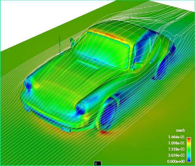
The ducktail is probably working in my favor. I say that not with a whole lot of knowledge to back it up, but because it's the way the factory is doing it on the current 911 race models.

2010-porsche-911-gt3-cup-2-600x399.jpg


And I apologize for the off-the-garage-topic stuff eating up space, but I love this stuff, and there actually are some ways to test what the wing is doing -- even when wind tunnel rental time is not in the budget. I use wool tufts to track where the air is moving -

Tufts1149651248.jpg


- but the more-useful tool is a pair of 1995 Lincoln Continental ride-height sensors, scored for $5 each on Ebay and attached to my front and rear suspension components. They let me track differences in the ride height of the car with the little computer in my car's data logger.

RideHeight1159215051.jpg


Here's a graph from the data logger. This was when I found a very remote stretch of empty highway where I could bring the car up to a set speed (100 mph) for a few seconds -- then exit at the next exit and do the same thing in the other direction. So the graph shows two 100-mph pieces (the top section is car speed, the lower two sections are front and rear ride height), and also some not-useful data in between where I'm speeding up, slowing down, or turning around at the exit. But I repeated this with the wing set at different angles, so I could see if the wing was changing the car's ride height with the different wing angles at the 100-mph test speed.

Data1159630646.jpg


Here's a detail segment where I've labeled the different wing angles.

WingAnglesPlusSplitOnly1159630700.jpg


Once I get the support structure issues worked out again for these new uprights, I want to go out and do the same type of testing with this newer wing and the four different angles it can run at.

But back to the new uprights.

I think it might make sense to add some cables, so that the allthread will really only be asked to work in tension (not compression), and a horizontal cable will also eliminate any squat-and-spread between the rear 'legs' of the uprights when the wing is pushing down the most.

Any stuff I can put right behind the ducktail would (I assume) come with less of a drag penalty. So one idea is to try and keep the new diagonal on the lower part of the upright, like this:

Option A

opt1i.jpg


But that might mean too much of a compromise in terms of strength. So another way to go would be to take the drag hit and run it in the strongest position.

Option B

opt2b.jpg


But then, that gets me thinking that maybe I eliminate the allthread and its weight, and just go with two cables, each providing strength in tension -- and crossed over each other so that compression is less of an issue.

opt3.jpg


I like the idea of using a tape wrap to create something like an aerodynamic shape for the cable, but in thinking about it I also imagine it could flap like crazy in the wind and actually produce more drag. But then, I don't actually know very much of this stuff. Maybe the drag from a 1/8" (or thinner) wire rope would simply not be worth worrying about.

Opinions?

Can't say I read all the posts but what about putting the wire in a shrink tubing sleeve. That should allow for smoother airflow.
 

phill u7c

Active member
Joined
Jan 9, 2009
Messages
38
Location
Cambridge, UK
Just to throw my 2 cents worth into the pot:
Motor racing set-up is all about compromise
Why does the car create lift? Well the top surface of the car is longer than the underside. So if you trust that every piece of air on earth is attached to every other piece of air on earth, then you can see that the air travelling across the top of the car has further to travel then the air travelling across the underside, but still has to get to the back at the same time, so the air on top has to speed-up, and as a result gets thinner and has less pressure compared to the air on the underside of the car thus lift is created.
Lengthening the front splitter parallel to the floor will help alter the split point of the air hitting the front of the car in your favour, but there is a limit, you would have to experiment to find that point. Also at the rear the wing height will have an influence on the rejoin point behind the car, there are several points to work with here, the higher the wing, the more un-disturbed air you move across the wing the better, the larger the wing endplates the more stability the wing will have and the further back you can mount the wing the more leverage you will have on the rear axle.
Firstly, have you given any thought to what will happen to the aero dynamically? Under braking the front splitter will drop maybe all the way to the floor destroying the aero effect just when you need it. I.e. braking and turning into a corner. Similarly under acceleration the front will come up and the rear will sink, again destroying the aero effect.

So what is the cure, well the short answer is there isn’t one ...........................
As I wrote at the start, motoracing is all about compromise, in order to get the most out of the aero you need a consistent platform, so the car needs to be as stiffly sprung as possible, but in order for the car to brake effectively there needs to be a degree of compliance in the suspension. You will have to experiment with this and find what works for you, but spring pre-load and bump rubbers work well provided you don’t stop any movement too quickly , otherwise over-steer and under-steer will bite you hard.

Oh and one final point on aero, turning wheels screws everything up, the less air carried inside the wheel arches the better, In touring cars we used to fill the arches with 2 part foam (like plumbers use to fill holes in walls and around pipes) leaving just enough room for the steered wheels to turn, and for all 4 wheels to move with the suspension.
I hope all this will give you food for thought. All the info above comes from spending the last 30 odd years in Formula 1, GT1, European touring cars and other assorted ways of turning money into noise.
I do so hope some of it will help you have as much success on the track as you have had with your garage.
 
OP
J

Jack Olsen

Super Moderator
Staff member
Joined
Mar 22, 2009
Messages
6,678
Location
Los Angeles
Thanks, guys.

Bob, I put the thicker wire in, mostly because I'm threading it through the upright itself to reduce the number of pieces involved, so there will be friction acting on it -- so I'd rather err on the side of too strong. Granted, the aluminum is softer than the stainless, and the holes I cut got rounded off with a countersink bit to keep them from having anything like a cutting edge. But friction will allow water to wear through stone, over time. So I think the thicker cable will buy me more time. I'll do regular visual inspections to make sure it's not fraying.

Today I put the crossbrace in. It's there because I think it will helpreduce wobble in the pillars. The base pieces are pretty strong, but the uprights can bow, and this piece will reduce that without any significant aero penalty -- since it's right behind the spoiler.

xmenwv.jpg


Sorry about the shaky image

Now, here's where my anorexia kicks in. The allthread piece I can use for this weighs six ounces. And it's more flexible than I'd like, without any kind of jacket on it. I picked up a piece of carbon fiber tube, which weighs almost nothing and is quite a bit more rigid. Here it is cut to size:

tubular.jpg


I cut some small lengths of allthread to mount it, and adhered them inside the tubing with 3M Scotch-Weld DP-460 structural adhesive.

lightweight.jpg


Even with the allthread inserts and bolts, this piece only weighs 2.1 ounces.

Here they are side by side:

optionsoh.jpg


My concern is how the adhesive will hold up to the vibration and stress of this thing in use. If it fails, I don't think the wing will fail right away -- so it's something I can try and then replace if the adhesive gives up its grip. But I COULD also simply sleeve the long single piece of allthread with the carbon fiber and bite the bullet on the extra four ounces of weight.

I'm still trying to decide which way is better -- although by morning the Scotch-Weld will have set and the decision will be out of my hands.

(And thanks, phill u7c. I'm going to write up a separate reply for your post when I get some time this evening.)
 

JakeKohl

Well-known member
Joined
Feb 23, 2012
Messages
1,365
Location
Greenville, SC
Jack, I think you will be shocked with how well that epoxy will hold those all-thread pieces inside the tubing. I work with that tubing a bit from time to time and I'm sure the tubing will fail before the all-thread comes lose. If strength/stiffness becomes an issue, you may want to switch to a filament wound tube instead of the pultruded tubing. Most of this stiffness increase for the filament wound is in the torsional axis but you could still see some appreciable difference in overall stiffness / strength.
 
To avoid these ads, REGISTER NOW!

YoungMedic

Well-known member
Joined
Jul 10, 2012
Messages
170
Location
Florida
The amount of knowledge and skill floating around this board is truly amazing. I can only imagine what world problems could be solved should they be stated in a thread on the GJ

:beer:
 

Modern Jess

Well-known member
Joined
Jan 2, 2011
Messages
1,362
Location
Bay Area, California
Hey Jack - What's the sum of the aero profile of all the cross braces, vs the aero profile of thicker uprights? I'm wondering if there's a break-even point at which you'd be better off with thicker uprights.

Better yet, stamping a subtle ridge into the upright would give it some strength in the third dimension without adding weight, though it would add slightly to the aero profile.

My gut tells me (without anything to back it up) that the aero impact of those cross braces is going to create a bit of turbulence behind you. But then, this is a subject where laypeople such as myself generally know much less than they think they do. :)
 

pwschuh

Well-known member
Joined
Jun 29, 2012
Messages
240
Location
Mid-Atlantic
"Aerodynamics is for people who can't build engines." -Eleanor Roosevelt

Or maybe it was Smokey Yunick. I forget.
 
Last edited:

bduc61

New member
Joined
Feb 29, 2012
Messages
3
Hi
A little hello from France across the pond
read most of this amazing thread
Flabbergasted is the word
congratulations for your workmanship, attention to detail and result - bravo :thumbup:

Myself ,
I managed to organize my garage with a workbench found when I bought the house and around it, I arranged it mostly with cabinets and drawers found in the street ! ( in France, quite often , once a month the town clears junk - old appliance etc... so people put stuff on the pavement )
but its not a good looking organization !

Unfortunately it is a small garage and is now more and more cluttered, as
It is used to park all the family bicycles and all my parts as I never buy a new bicyle and am mostly rebuilding bikes with parts found in France, quite often in the UK and sometimes even the USA ( mostly MTB's from the nineties as I don't like "can or plastic" frames ! and road and city bikes)

and I have got too many bikes ! fortunately less expensive than a porsche ;-)

reading your post, you gave me courage to be more "pro" and I am now willing to improve it and will work on it ;-)

Unfortunately
apart from good vices, good quality equipment does not come cheap in France !
stuff like you lista cabinet are more at the tune of 600 USD or more for one !

Keep the good work :thumbup:
 

DocRocket

Well-known member
Joined
Feb 24, 2011
Messages
278
Hey Jack - What's the sum of the aero profile of all the cross braces, vs the aero profile of thicker uprights? I'm wondering if there's a break-even point at which you'd be better off with thicker uprights.

Better yet, stamping a subtle ridge into the upright would give it some strength in the third dimension without adding weight, though it would add slightly to the aero profile.

My gut tells me (without anything to back it up) that the aero impact of those cross braces is going to create a bit of turbulence behind you. But then, this is a subject where laypeople such as myself generally know much less than they think they do. :)

Last things first: The flow behind the Porsche is already turbulent--there is ZERO chance that the flow over the rear of the Porsche is laminar--that requires a less than 5% negative slope--so to drop the ~25 inches from the roof to the back bumper, the car would be over 42 feet long. That would create more surface drag than the turbulence creates. That being said, the drag on a 0.375" cylinder in turbulent flow, at about 120 mph should be about 3.5 lbs, or 1.3% of the car's drag (or less). Long answer, but the rods are a miniscule contribution to the car's drag--other, bigger targets are out there (headlights?).

At some point, there may be a streamlined, thicker shape for the uprights that would be stiff enough to ditch the cross bracing, but a couple of things would probably count against it for an amateur racer (read someone without sponsors...): 1) the shape would be much harder to manufacture with home tools (assuming no home 5 axis CNC mill...) 2) You are almost certainly going to get into a point of needing to do some real wind tunnel or Computational Fluids testing to really get it right, since the shape would probably need to be tuned carefully, 3) this all costs $^3 (cubic dollars), and the gain is probably not there (see above--there are probably bigger reductions to be had elsewhere, the uprights are probably not contributing more than 10-20lbs of drag together at 120mph.

Stamping, or rolling, a ridge would definitely contribute stiffness, and probably not too much extra drag. Again, even largish increases are probably not in the top ten contributors for the car--I would bet that the wing itself is making quite a bit more drag than the support structure--if it is operating near stall (should be about 15 degrees), then the section lift coefficient should be about 1.5 and the section drag coefficient should be about 1% of that, but the lift creates drag too, and the total should be about 15% of the lift--a 4 ft wide by 1 ft chord wing at 120 mph should produce (under these conditions) abou1 220 lbs of lift (downforce) and about 35 lbs of drag--there is a reason that a lot of race car drag coefficients are poor compared to a lot of street car drag coefficients--downforce causes more drag.
 

luvit

Well-known member
Joined
Jul 11, 2011
Messages
1,580
.
why do we need to reinvent the wheel? the ricers can teach you a thing or two, jack.

.
 

Modern Jess

Well-known member
Joined
Jan 2, 2011
Messages
1,362
Location
Bay Area, California
Agreed on all points, DocRocket. But this goes back to my original point, I think. Why not just make the uprights a bit stronger? I think, from reading previous posts here, that Jack is fairly concerned about weight. As a scooter rider who spends a lot of time on sub-20hp machines, I can appreciate this, though the added weight (just like the aero profile of the cross braces) is probably fairly low down the list of Things That Matter on Jack's car.
 

DocRocket

Well-known member
Joined
Feb 24, 2011
Messages
278
I assumed, and Jack, or others may be able to correct me on this one, but I assumed that some of the material choice was based on availability at reasonable cost
 
OP
J

Jack Olsen

Super Moderator
Staff member
Joined
Mar 22, 2009
Messages
6,678
Location
Los Angeles
Just to throw my 2 cents worth into the pot:
Motor racing set-up is all about compromise. Why does the car create lift? Well the top surface of the car is longer than the underside. So if you trust that every piece of air on earth is attached to every other piece of air on earth, then you can see that the air travelling across the top of the car has further to travel then the air travelling across the underside, but still has to get to the back at the same time, so the air on top has to speed-up, and as a result gets thinner and has less pressure compared to the air on the underside of the car thus lift is created.
Lengthening the front splitter parallel to the floor will help alter the split point of the air hitting the front of the car in your favour, but there is a limit, you would have to experiment to find that point. Also at the rear the wing height will have an influence on the rejoin point behind the car, there are several points to work with here, the higher the wing, the more un-disturbed air you move across the wing the better, the larger the wing endplates the more stability the wing will have and the further back you can mount the wing the more leverage you will have on the rear axle.
Firstly, have you given any thought to what will happen to the aero dynamically? Under braking the front splitter will drop maybe all the way to the floor destroying the aero effect just when you need it. I.e. braking and turning into a corner. Similarly under acceleration the front will come up and the rear will sink, again destroying the aero effect.

So what is the cure, well the short answer is there isn’t one ...........................
As I wrote at the start, motoracing is all about compromise, in order to get the most out of the aero you need a consistent platform, so the car needs to be as stiffly sprung as possible, but in order for the car to brake effectively there needs to be a degree of compliance in the suspension. You will have to experiment with this and find what works for you, but spring pre-load and bump rubbers work well provided you don’t stop any movement too quickly , otherwise over-steer and under-steer will bite you hard.

Oh and one final point on aero, turning wheels screws everything up, the less air carried inside the wheel arches the better, In touring cars we used to fill the arches with 2 part foam (like plumbers use to fill holes in walls and around pipes) leaving just enough room for the steered wheels to turn, and for all 4 wheels to move with the suspension.
I hope all this will give you food for thought. All the info above comes from spending the last 30 odd years in Formula 1, GT1, European touring cars and other assorted ways of turning money into noise.
I do so hope some of it will help you have as much success on the track as you have had with your garage.

Thanks you for that, phill u7c. I could never hold myself up as an expert on this stuff, but I've been fortunate to have some very generous individuals help me out. My car has been modeled and run in simulation form in the software of an aeronautics company. It was surprising to see that (in theory) moving my wing 4" lower -- or higher -- both led to a drop-off in its performance. Every car is different, and -- like you point out -- on a production car, especially, you're dealing with a non-stop line of compromises.

Years back, I tested some underbody stuff that I came up with, and got decent results in a straight line. But they were terrible in actual use for the reasons you point out. Unless your suspension movement is controlled, the underbelly of the car is going to move too much in relation to the track surface and all of the magic you've conjured up is going to instantly disappear just when you actually need it.

In any case, you've got me thinking about doing something with my wheel wells, now -- especially since some testing I did this week shows me that I need to do more for my front axle. Porsche improved the air management of the wheel wells in 1990. I can follow their lead and probably get some benefit.

Thanks again for the input.

Jack, I think you will be shocked with how well that epoxy will hold those all-thread pieces inside the tubing. I work with that tubing a bit from time to time and I'm sure the tubing will fail before the all-thread comes lose. If strength/stiffness becomes an issue, you may want to switch to a filament wound tube instead of the pultruded tubing. Most of this stiffness increase for the filament wound is in the torsional axis but you could still see some appreciable difference in overall stiffness / strength.
It's held up great so far. That Scotch-Weld stuff is pretty amazing. The aluminum wing I made about seven years ago didn't have any fasteners in it. Just $50 worth of aluminum and about $100 worth of that adhesive -- and it held up to six years of hard use with no issues.

The amount of knowledge and skill floating around this board is truly amazing. I can only imagine what world problems could be solved should they be stated in a thread on the GJ

:beer:
I agree. I'm always amazed (and a little humbled) by the generosity and knowledge that shows up in these forums (and sometimes in my email in-box).

Hey Jack - What's the sum of the aero profile of all the cross braces, vs the aero profile of thicker uprights? I'm wondering if there's a break-even point at which you'd be better off with thicker uprights.

Better yet, stamping a subtle ridge into the upright would give it some strength in the third dimension without adding weight, though it would add slightly to the aero profile.

My gut tells me (without anything to back it up) that the aero impact of those cross braces is going to create a bit of turbulence behind you. But then, this is a subject where laypeople such as myself generally know much less than they think they do. :)
The across braces are needed because of the way I attach the uprights to my car, not because of the strength of the uprights themselves. I have to bolt the things to the underside of my deckled, which just rules out any good way to provide lateral reinforcement -- without damaging the paint on the visible part of the car. I kept making the uprights thinner only because I wanted to save weight. Oddly, I've now made slightly heavier uprights that have much lighter cross braces.

"Aerodynamics is for people who can't build engines." -Eleanor Roosevelt

Or maybe it was Smokey Yunick. I forget.
But aluminum is dirt cheap compared to Porsche engine work.
 
OP
J

Jack Olsen

Super Moderator
Staff member
Joined
Mar 22, 2009
Messages
6,678
Location
Los Angeles
Last things first: The flow behind the Porsche is already turbulent--there is ZERO chance that the flow over the rear of the Porsche is laminar--that requires a less than 5% negative slope--so to drop the ~25 inches from the roof to the back bumper, the car would be over 42 feet long. That would create more surface drag than the turbulence creates. That being said, the drag on a 0.375" cylinder in turbulent flow, at about 120 mph should be about 3.5 lbs, or 1.3% of the car's drag (or less). Long answer, but the rods are a miniscule contribution to the car's drag--other, bigger targets are out there (headlights?).

At some point, there may be a streamlined, thicker shape for the uprights that would be stiff enough to ditch the cross bracing, but a couple of things would probably count against it for an amateur racer (read someone without sponsors...): 1) the shape would be much harder to manufacture with home tools (assuming no home 5 axis CNC mill...) 2) You are almost certainly going to get into a point of needing to do some real wind tunnel or Computational Fluids testing to really get it right, since the shape would probably need to be tuned carefully, 3) this all costs $^3 (cubic dollars), and the gain is probably not there (see above--there are probably bigger reductions to be had elsewhere, the uprights are probably not contributing more than 10-20lbs of drag together at 120mph.

Stamping, or rolling, a ridge would definitely contribute stiffness, and probably not too much extra drag. Again, even largish increases are probably not in the top ten contributors for the car--I would bet that the wing itself is making quite a bit more drag than the support structure--if it is operating near stall (should be about 15 degrees), then the section lift coefficient should be about 1.5 and the section drag coefficient should be about 1% of that, but the lift creates drag too, and the total should be about 15% of the lift--a 4 ft wide by 1 ft chord wing at 120 mph should produce (under these conditions) abou1 220 lbs of lift (downforce) and about 35 lbs of drag--there is a reason that a lot of race car drag coefficients are poor compared to a lot of street car drag coefficients--downforce causes more drag.
Thanks. I can see the value to rolling the edge(s). With these new uprights, I don't think I'll need it. (But then, I've said that before and been wrong.) And I wonder if the way the wing is cantilevered out back makes it actually improve its rear-axle downforce numbers even as it passes (or flirts with) stall. The reason I'm wondering about that is that I took the thing out and tested it, and I definitely get the best downforce from the wing at a pretty ridiculous angle (around 20°). Now, according to the numbers, my airfoil shape should be at its best at right around 15°.

LiftData031153915383.gif


Mine is the NACA63-520M (blue line).

I don't know if the way camber has been added to my airfoil's profile means I'm measuring the wing's angle incorrectly -- and maybe it doesn't matter. I get my best downward push at around 20°, and there's still pretty good adhesion along the underside of the wing at that setting.

Wing+U+20+91159142269.jpg


I did a quick piece of testing earlier this week and found I am getting an odd see-saw effect, in that as the rear wing gets more effective, the front end comes up (relative to less-aggressive angles of attack with the rear wing). Although it's worth noting that when I remove the front splitter, the front comes up even higher, even without a wing in back.

If I put a 4x8 sheet of plywood on uprights behind my car and set it absolutely flat up and down -- a 90° angle of attack -- the drag from it would push down on the rear axles, since it's hanging out behind them.


.
why do we need to reinvent the wheel? the ricers can teach you a thing or two, jack.
You mean the decorative wings you see on Hondas and such? Well, I have learned from them. But the knowledge is mostly about how ridiculous I look when I'm running a wing at all. But on the track, I'll take the ridiculous look if it makes me faster.

Agreed on all points, DocRocket. But this goes back to my original point, I think. Why not just make the uprights a bit stronger? I think, from reading previous posts here, that Jack is fairly concerned about weight. As a scooter rider who spends a lot of time on sub-20hp machines, I can appreciate this, though the added weight (just like the aero profile of the cross braces) is probably fairly low down the list of Things That Matter on Jack's car.
Again, it's because of my odd way of mounting the whole assembly. There's very little 'ankle' strength, so I have to make the whole thing rigid.

I assumed, and Jack, or others may be able to correct me on this one, but I assumed that some of the material choice was based on availability at reasonable cost
Yes. I'm not poor, but I'm frugal to a fault. It pained me to spend $80 on this new aluminum alloy, and it further hurt me to spring for a $29 piece of carbon fiber to save a little weight over allthread. This is low budget work, here. That's what I like about it.
 
OP
J

Jack Olsen

Super Moderator
Staff member
Joined
Mar 22, 2009
Messages
6,678
Location
Los Angeles
Hi
A little hello from France across the pond
read most of this amazing thread
Flabbergasted is the word
congratulations for your workmanship, attention to detail and result - bravo :thumbup:

Myself ,
I managed to organize my garage with a workbench found when I bought the house and around it, I arranged it mostly with cabinets and drawers found in the street ! ( in France, quite often , once a month the town clears junk - old appliance etc... so people put stuff on the pavement )
but its not a good looking organization !

Unfortunately it is a small garage and is now more and more cluttered, as
It is used to park all the family bicycles and all my parts as I never buy a new bicyle and am mostly rebuilding bikes with parts found in France, quite often in the UK and sometimes even the USA ( mostly MTB's from the nineties as I don't like "can or plastic" frames ! and road and city bikes)

and I have got too many bikes ! fortunately less expensive than a porsche ;-)

reading your post, you gave me courage to be more "pro" and I am now willing to improve it and will work on it ;-)

Unfortunately
apart from good vices, good quality equipment does not come cheap in France !
stuff like you lista cabinet are more at the tune of 600 USD or more for one !

Keep the good work :thumbup:
Thanks! Keep us posted on your progress. I'm happy to have provided some inspiration.
 

DocRocket

Well-known member
Joined
Feb 24, 2011
Messages
278
When you look at Angle of Attack, it is always measured from the actual relative wind. What that tells me is that your actual AOA is 15 degrees when you think it is at 20 degrees (or at 9, depending on how you are determining it). The flow over the back window of a 911 is either separated or turbulent, that window is not close enough to horizontal to have attached, laminar flow. In either case, the flow about 18-24 inches above the window/rear deck is not parallel to the rear deck--you have a rapidly growing boundary layer, and the flow above that is parallel to the boundary layer's upper surface, not the car's upper surface. Also, the ducktail spoiler is probably having an impact on the effective angle of attack of the wing, forcing some extra flow over the bottom surface of the wing, which will probably tend to move the lift curve up and to the right a little--zero lift AOA probably stays in about the same place, but the wing will most likely stall at a higher AOA and support a higher lift coefficient--might work like a blown flap or upper surface blowing on an aircraft wing (look at the 1970's YC-15 cargo airplane for an example of what that could look like).
 

luvit

Well-known member
Joined
Jul 11, 2011
Messages
1,580
luvit said:
why do we need to reinvent the wheel? the ricers can teach you a thing or two, jack.
You mean the decorative wings you see on Hondas and such? Well, I have learned from them. But the knowledge is mostly about how ridiculous I look when I'm running a wing at all. But on the track, I'll take the ridiculous look if it makes me faster.
Now there's another valuable lesson. You should be racing in a honda. ;)
Great Fun on your wing subject, btw..
how much prep time do you have on camera set-up before each run?
 

alpinewhite

Well-known member
Joined
Aug 4, 2012
Messages
1,315
Location
Orange County, California, USA
I actually DID have a plan to use at least one of the two extra drawers -- since I believe in using the whole buffalo and all of that. In shortening the top of the desk to allow the cabinet to fit, I reduced the space where I sit to the exact width of one of the drawers. So it seemed a no-brainer to put a shallow drawer under the main bench, right where I sit.

redbench.jpg


But as soon as I started filling the drawers, it seemed like a shallow one would be more useful in the stack. So I rearranged it. Now I could still fit a 3" drawer there -- I checked the clearance. But I'm on the fence about it. I've got the parts set aside. But it may be that both drawers end up as donors to the drawer swap thread that someone else organized. We'll see.
Are your two drawers still orphans? If not, where are they living now? Inquiring minds want to know.
 
OP
J

Jack Olsen

Super Moderator
Staff member
Joined
Mar 22, 2009
Messages
6,678
Location
Los Angeles
When you look at Angle of Attack, it is always measured from the actual relative wind. What that tells me is that your actual AOA is 15 degrees when you think it is at 20 degrees (or at 9, depending on how you are determining it). The flow over the back window of a 911 is either separated or turbulent, that window is not close enough to horizontal to have attached, laminar flow. In either case, the flow about 18-24 inches above the window/rear deck is not parallel to the rear deck--you have a rapidly growing boundary layer, and the flow above that is parallel to the boundary layer's upper surface, not the car's upper surface. Also, the ducktail spoiler is probably having an impact on the effective angle of attack of the wing, forcing some extra flow over the bottom surface of the wing, which will probably tend to move the lift curve up and to the right a little--zero lift AOA probably stays in about the same place, but the wing will most likely stall at a higher AOA and support a higher lift coefficient--might work like a blown flap or upper surface blowing on an aircraft wing (look at the 1970's YC-15 cargo airplane for an example of what that could look like).

I've done some wool tuft testing that pointed to 11° for the incoming airflow. But I suspect my data is not giving me a clear look at the whole picture -- and that what you're describing is probably what's actually happening.

Leading+Edge+Yarn1159141659.jpg


Little+Tuft+Test1331677628.jpg


Min+Blow+041149901311.jpg


Are your two drawers still orphans? If not, where are they living now? Inquiring minds want to know.
They're currently sitting in a stack of stuff ready to go out for scrap. I know there's a drawer swap thread somewhere, which I keep meaning to check. But these are older drawers -- I'm not sure of their compatibility with the newer Lista units.
 

DocRocket

Well-known member
Joined
Feb 24, 2011
Messages
278
I've done some wool tuft testing that pointed to 11° for the incoming airflow. But I suspect my data is not giving me a clear look at the whole picture -- and that what you're describing is probably what's actually happening.

Leading+Edge+Yarn1159141659.jpg


Little+Tuft+Test1331677628.jpg


Min+Blow+041149901311.jpg


QUOTE]

The wing can affect airflow direction a significant distance upstream at low speeds (and 130 mph is low speed, only about Mach 0.2). Since, by eye, your tufts are only about 1/4 chord in front, there may be some turning to the flow caused by the wing at that point. Yarn tests are good, but there are two issues: 1) you cannot put yarn tufts everywhere you would want to, and hanging them out in the flow does change the flow, and 2) it is hard to get angles accurately with them when your cameras are at funny angles too. I would not be surprised to find a 2-3 degree error in angles based on the compound camera angles I am seeing there (and where I would think you could mount a camera on a 911, it appears the camera may be both below and in front of the tufts--makes the geometry more difficult and small changes can make a difference). It really would not take much to put you nearer the 15 degree AOA, and since you do not have that specific airfoil, we would have to figure out which airfoil you actually have (you may have posted that, but I am too lazy to read back through all the pages of this thread to find it, and I do not have all the airfoil tables at home anyway, I would have to find a University library to get the data, if it is a NACA airfoil). The AOA I cited is only for a specific airfoil, others will reach max lift at different angles.

Overall, if you are maxing the lift at the angle you are running, then you have maxed out the downforce, and what the actual AOA is, just doesn't matter. Love to see people try out the aero stuff, and your work looks good to me. Remember, the Wright brothers made their first airplane on testing much like what you are doing, and a lot of guess and check.:thumbup:
 
OP
J

Jack Olsen

Super Moderator
Staff member
Joined
Mar 22, 2009
Messages
6,678
Location
Los Angeles
Thanks, guys.

DocRocket, I appreciate the input and the kind words. For my application, the testing and data doesn't have to be very thorough or comprehensive -- I just have to find out what works better or worse, like you say. My next step is going to be to improve the insides of the wheel wells -- because it will be easy and cheap. Then maybe a little testing with overall rake. We'll see.

And 'The Boss,' your signature has a great lyric from what might be my favorite song written by Springsteen -- who is definitely the most-played artist on my garage stereo.
 
Last edited:
To avoid these ads, REGISTER NOW!
Top Bottom