TerryH
Well-known member
I should not even be allowed to read this thread. There are some incredibly talented guys posting some incredible work here. Amazing.

What is the point of dimple dying something like what ZT built??just astetics?
I at work I build calf milk pasteurizers and when I build the tanks it's rolles sheet metal and I have to weld the seam and a cap on one end, and the holes all get pulled out like dimple dies do but for us it's so we can weld ferrals on cleanly since it all gets purge welded. So that's the only reason I see those used....


You guys are my heroes!
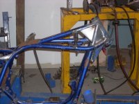
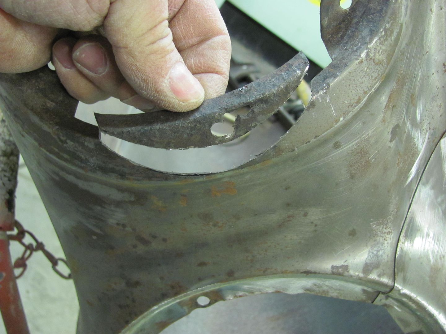
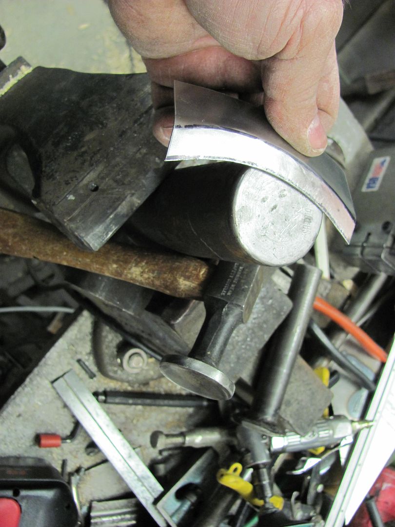
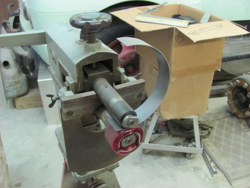
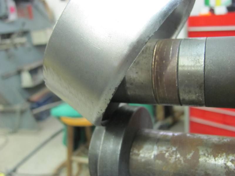
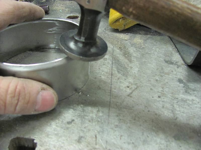
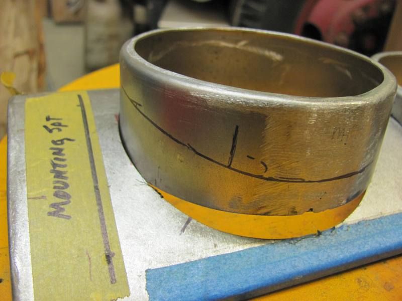
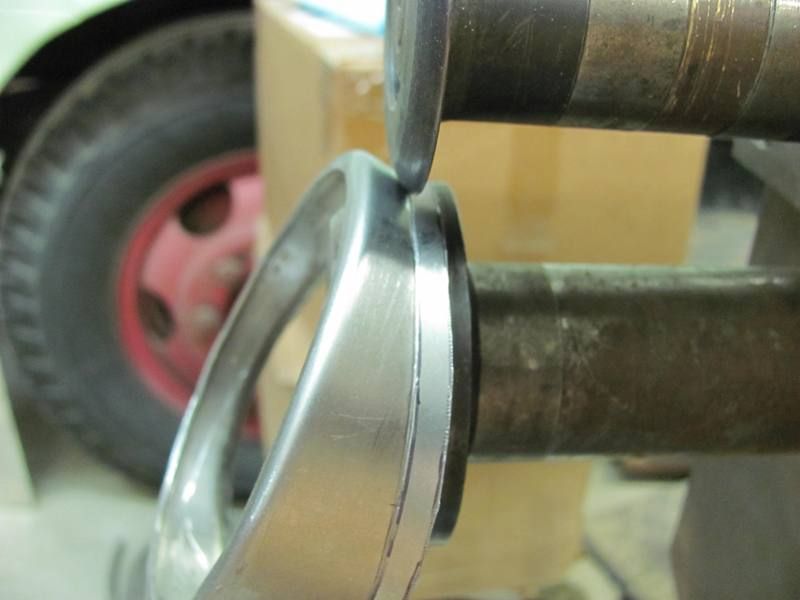
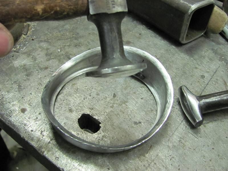
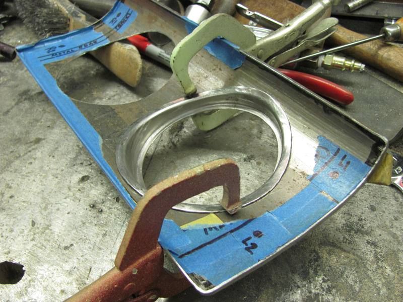
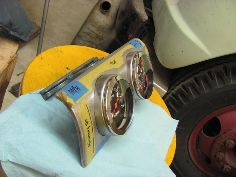
Used a .035 x 3" cutoff wheel to cut it out, then a 1.5 dia drum sander to clean up the opening on the fender. If not using the tipping wheel, two opposing cresent wrenches could have easily accomplished the task of bending.
What's interesting about this piece is that you're bending a flange on curved sheet. When I've attempted that in the past, the piece tends to straighten or the flange part bunches up. Would have taken me several tries to get this piece looking anything close to right.

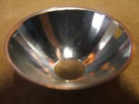
Nothing along the lines of the multi talented on here and what's shown, but here's a couple of reflectors that were made for aircraft lighting. I don't have a lot of things showing what I used to do at work.

What is the point of dimple dying something like what ZT built??just astetics?
I at work I build calf milk pasteurizers and when I build the tanks it's rolles sheet metal and I have to weld the seam and a cap on one end, and the holes all get pulled out like dimple dies do but for us it's so we can weld ferrals on cleanly since it all gets purge welded. So that's the only reason I see those used....
i think the dimpling serves several purposes
adds rigidity stiffness
reduces weight
aesthetically pleasing
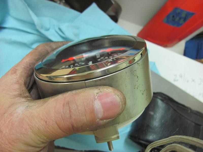
could also be functional ie someone mentioned using it in a dash panel for gauges, maybe it could allow for clearance issues or for allowing access like a pass through for wires or a hose
ow about some detail on how you did it? Nice work
Kevin, is that plated copper? I'm with Jim, fess up on some forming details!
Jim, haven't made it back out your way again, been travelling the other direction (UK), but have you made it to the hood forming yet?
Those are stamping or formed, Am I right? How would you machine tooling for something like that conventionally?? With a rotary table?
Must be nightmarish to machine.


Details, pics....?
State of the art manufacturing facility!

Tapered aluminum downspouts at a sewage treatment plant outside of San Diego. They tapered from 36" Diameter to 6" at the bottom. They were about 40 feet tall, and made in 8 pieces, welded together.


There's been tons and tons of sheetmetal formed with those high tech tools over the years
I can understand them being downspouts, but is this pic before gutters or is just the large diameter catching water.
It was a flat roof. The scuppers and overflows are hidden. These were functional, but also decorative downspouts.
I can see it now when looking at the pics since you said that. I see where it is coming in on the R.H. downspout.
So how long were the rollers to form them? Did you use powered or stomp shears to cut the material or cut them by hand? Nice job though to say the least.
Here is another part that I made. The outside company that was making it decided they didn't need our work anymore. It doesn't look like much, but no one knew how to make it. What it is, is a 1" O.D. aluminum tube that had to be bent or formed to something like 25 degrees. It was not allowed to have any kinks in it nor was it allowed to be flattened out in the forming process. When I first tried it, I made up a jig with rollers that fit the tube. One end had to be clamped then a roller would come around and roll the tube. It flattened the tube in the bend. So second try was fill it with water, freeze it, then try rolling it. It would crush the ice. Third try was to weld a cap on it, fill it with water, screw a cap on the other end, then roll it. It would still crush the ice.
I though for a while and figured, why not try to basically extrude it. I took two blocks of aluminum and cut the tube form into the blocks. Half in one block and half in the other block, then added some dowels for alignment. A little bit of grease, clamp both halves together, drop the tube into the top hole and shove it down with an arbor press. The tube formed and was within .005 all through the formation of the bend. And with minimal scrap. I left maybe .500 on the short end to fit into the mill fixture for trimming to the correct angle. And on a side note, the mill fixture used was the same one I made maybe 25 years ago. It makes one feel good that a piece of tooling lasted that long. BTW.....the aluminum tube gets knurled on the long end after forming and trimming and eventually welded to a searchlight that goes into helicopters.
Here is one other part made that no one knew how to machine. This piece was a little ***** to do and everything as far as dimensions absolutely had to be within .005 everywhere. Not only is it machined on top but also underneath. Every facet is a compound angle. And what is interesting and also embarrassing, not for me but for others, are the people that call theirself a Toolmaker and absolutely do not know how to figure a compound angle. Then you get in a discussion with them and find out they been making parts wrong for a long while.
")
I can understand them being downspouts, but is this pic before gutters or is just the large diameter catching water.
Details, pics....?


Check out what my 16 year old made for his high school project.
I showed him the basics by bashing out a part with a hammer and anvil. One part only, and he entirely made this by himself.
The flower and stem are all Alu. hot glued together.
He spent hours on it.
Sure makes his Daddy proud!
I've made flowers before but they were no where near as nice as his.