To avoid these ads, REGISTER NOW!

Outlets connected to switch - Needs them always on. Help!

maximus20895

Active member
Joined
Aug 3, 2012
Messages
43
Hello,

I recently moved into a new home and I discovered that all my outlets are connected to a switch. I do not know if that was intentional as this is a bed room and I don't see the advantage for every single outlet to be connect to a switch.

Anyways, I would like them all to be on all the time. The switch that they are connected two really has two switches, one is the light and the other are the outlets.

I will also say, I am planning on buying a fan in the near future and I would also like the first switch to turn on the light in the fan like it does currently (albeit just a light for now) and the other to turn on just the fan.

My first priority is making all these outlets on all the time and bypass the switch. How do I go about doing that?

Thanks!
 
To avoid these ads, REGISTER NOW!

2ManyProjects

Well-known member
Joined
Jul 18, 2013
Messages
757
Hello,

I recently moved into a new home and I discovered that all my outlets are connected to a switch.

OK, first... While your question might seem simple to you, there are actually enough different variables involved that we need to be rather fussy about defining EXACTLY what you're dealing with. Guessing at things helps no one, especially if we guess wrong.

So, with that in mind, when you say "...all my outlets...", are you referring to every outlet in the house being controlled by a single switch (which, as silly as that might seem, is exactly what the above-quoted sentence implies)? Or that merely all the outlets in one room are controlled by a single switch? Or that several groups of outlets (perhaps in different rooms) are each controlled by different switches? Or what? ALSO... When you say "every outlet", are you referring to BOTH outlets of each duplex outlet fixture? Or only one of them (with the other remaining live regardless of switch position)? Be specific, and be detailed.

I do not know if that was intentional as this is a bed room and I don't see the advantage for every single outlet to be connect to a switch.

As touched on above, it is fairly common practice to "split" duplex outlets, and wire them up so that one outlet is controlled by a wall switch (such as to turn on a table lamp or similar when entering the room), while the other outlet in that duplex remains live at all times. For example, all the outlets the Living Room in my shore house are done this way, using a common switch near the entrance archway. When I throw that switch, two table lamps plus some low-intensity lighting in the entertainment center etagere come on. Ditto for all the bedrooms in both houses, none of which sport those Ghod-awful 1940s-style light fixtures mounted in the center of each ceiling (well actually, in the main residence, it's both outlets on one duplex per room which is switched -- not the ideal arrangement, but it works).

Anyways, I would like them all to be on all the time.

Before jumping to any conclusions, I would suggest that you confirm that BOTH outlets on each of those duplexes are indeed switched. If you already have one "always live" outlet at each duplex location, it would probably be better to leave things as-is.

The switch that they are connected two really has two switches, one is the light and the other are the outlets.

First, by "one is the light", are you referring perhaps to a ceiling-mounted light fixture? Or something else?

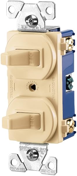
Second, by "really has two switches" do you mean it is a "duplex"-style switch, such as:

http://www.cooperindustries.com/con.../toggle_combination_switches_271_275_276.html
71AkeppF8rL._SY606_.jpg


???

These are usually intended for retrofit applications where you want to cram two switches into an existing single-gang box.

I will also say, I am planning on buying a fan in the near future and I would also like the first switch to turn on the light in the fan like it does currently (albeit just a light for now) and the other to turn on just the fan.

Fan circuits usually require specific dedicated wiring, typically using three-conductor (plus ground) cabling, AND a dedicated control device/switch (often supplied with the fan), especially if there is any variable speed control involved. You aren't going to cram that into the same single-gang box that already has a light switch or similar in it.

My first priority is making all these outlets on all the time and bypass the switch. How do I go about doing that?

It MIGHT be as simple as shutting off the power, removing the switch plate, pulling the switch assembly out of the box, disconnecting the appropriate "Hot" wires from the switch itself and twisting them together using a wire nut, then cramming the whole mess back into the box. HOWEVER... This also might exceed the "fill limit" for that single-gang box. And besides, given all the "unknowns" cited above, might not even work.

The first thing to do is determine, as definitively as possible, what you really have now. Pull the switch plates off the wall switch and all the outlets. Then carefully back out the screws affixing the switch and outlets to the boxes, and start examining the wiring and connections. I could take some wild guesses as to what you'll find; but that would be both premature and possibly misleading.

 
Last edited:

wyliesdiesels

Well-known member
Joined
Aug 14, 2012
Messages
20,054
Location
Modesto, CA
Controlling the fan/light with 2 switches will only work if theres 3 conductor cable between the switches and the fixture.
 

wyliesdiesels

Well-known member
Joined
Aug 14, 2012
Messages
20,054
Location
Modesto, CA
OK, first... While your question might seem simple to you, there are actually enough different variables involved that we need to be rather fussy about defining EXACTLY what you're dealing with. Guessing at things helps no one, especially if we guess wrong.

So, with that in mind, when you say "...all my outlets...", are you referring to every outlet in the house being controlled by a single switch (which, as silly as that might seem, is exactly what the above-quoted sentence implies)? Or that merely all the outlets in one room are controlled by a single switch? Or that several groups of outlets (perhaps in different rooms) are each controlled by different switches? Or what? ALSO... When you say "every outlet", are you referring to BOTH outlets of each duplex outlet fixture? Or only one of them (with the other remaining live regardless of switch position)? Be specific, and be detailed.

He said bedroom. No ***** would ever wire 'all' the outlets in a house on one or several switches. Never seen or heard of that in the 13+ yrs Ive been an electrician. Save yourself some breath(or callused fingers) by refraining from writing a whole book for each post!

As touched on above, it is fairly common practice to "split" duplex outlets, and wire them up so that one outlet is controlled by a wall switch (such as to turn on a table lamp or similar when entering the room), while the other outlet in that duplex remains live at all times. For example, all the outlets the Living Room in my shore house are done this way, using a common switch near the entrance archway. When I throw that switch, two table lamps plus some low-intensity lighting in the entertainment center etagere come on. Ditto for all the bedrooms in both houses, none of which sport those Ghod-awful 1940s-style light fixtures mounted in the center of each ceiling (well actually, in the main residence, it's both outlets on one duplex per room which is switched -- not the ideal arrangement, but it works).

FYI- this is called 'coasting' the outlet....

Before jumping to any conclusions, I would suggest that you confirm that BOTH outlets on each of those duplexes are indeed switched. If you already have one "always live" outlet at each duplex location, it would probably be better to leave things as-is.

First, by "one is the light", are you referring perhaps to a ceiling-mounted light fixture? Or something else?

Second, by "really has two switches" do you mean it is a "duplex"-style switch, such as:

http://www.cooperindustries.com/con.../toggle_combination_switches_271_275_276.html
71AkeppF8rL._SY606_.jpg


???

These are usually intended for retrofit applications where you want to cram two switches into an existing single-gang box.

For retrofit? According to who? Ive seen these used in new houses all the time. Saves time, switches and wire!

Fan circuits usually require specific dedicated wiring, typically using three-conductor (plus ground) cabling, AND a dedicated control device/switch (often supplied with the fan), especially if there is any variable speed control involved. You aren't going to cram that into the same single-gang box that already has a light switch or similar in it.

What are you talking about? Have u ever even installed a fan? Ive installed LOTS of fans over the years. There is no 'dedicated control device' that mounts in the switch junction box. For speed control on a non wireless fan, theres 2 chains, one for the light one for the fan speed. The motor has several winding taps that connect to the switch. On a wireless fan with an external receiver, the receiver sits above the fan in the drop ball bracket. It cant go anywhere else because it needs to connect to the separate light and fan leads. Some fancier fans have built in receivers...

It MIGHT be as simple as shutting off the power, removing the switch plate, pulling the switch assembly out of the box, disconnecting the appropriate "Hot" wires from the switch itself and twisting them together using a wire nut, then cramming the whole mess back into the box. HOWEVER...This also might exceed the "fill limit" for that single-gang box. And besides, given all the "unknowns" cited above, might not even work.

Huh? How would the fill limit be exceeded by adding a wire nut to 2 wires that already existed in the box in the first place. You have no idea what you're talking about!
 
Last edited:
OP
M

maximus20895

Active member
Joined
Aug 3, 2012
Messages
43
By all my outlets I mean all my outlets in my bedroom. This includes the top and bottom outlet of each outlet fixture. Every outlet in my bedroom is controlled by one switch.


The first switch controls a ceiling mounted light (which will soon the light that is built-in with the fan).

The second switch controls all the outlets in my bedroom like mentioned above.

By two switches I mean, 2 single switches in a double gang box. I have a picture to help you out further.


Since taking this picture I've seem to do something where the lights/outlets won't even come on. I tried turning the breaker switch on and as soon as I do that it trips and the switch goes in the middle. I do know what I did since I didn't disconnect any wires. I simply pulled the switches out so I could take a picture.

There seems to be 4 romex wires/bundles/whatever behind the gangbox. I do now know why, I would think that even if the outlets were controlled by a switch they all would be in a series or something, but then again I don't know much. Also, the light switch has a black wire that goes into the outlet switch, I do not know why. Lastly, there is a red wire that goes to the light switch. I also don't know why.

Here is a picture as I'm sure it will help more than what I can say:

outlet.jpg


Thanks again!
 
Last edited:

justsam

Well-known member
Joined
Aug 20, 2010
Messages
1,268
Location
Penngrove, California
"Coasting" is a new one for me, not that that I consider myself an electrician.

For me one hot and one switched is called a "half hot".
 
OP
M

maximus20895

Active member
Joined
Aug 3, 2012
Messages
43
Why? I didn't install any of these wires what so ever. This is what an electrician did, not me. I just took the wall plate off.

Please tell me what I did wrong by asking for advice before a do anything?
 

wyliesdiesels

Well-known member
Joined
Aug 14, 2012
Messages
20,054
Location
Modesto, CA
Why? I didn't install any of these wires what so ever. This is what an electrician did, not me. I just took the wall plate off.

Please tell me what I did wrong by asking for advice before a do anything?

Just ignore the naysayers. They dont have anything helpful to say so they post bad comments! Most of the posters on here arent electricians so u have to wade through BS!
 
OP
M

maximus20895

Active member
Joined
Aug 3, 2012
Messages
43
Thanks!

Asking questions is how I and most people learn so I don't understand why someone would put me down for asking questions.

Also, I just looked at another room and behind the switches looks exactly the same minus another romex so just 3 this time. Funny thing is that all the outlets in that room are hot all the time. I'm not exactly sure what the 2nd switch is for that room, maybe it's for a future fan.
 

pattenp

Well-known member
Joined
Jun 4, 2008
Messages
10,175
Location
Virginia - USA
You have done nothing wrong. I don't understand why some people feel the need to post comments that serve no purpose. Just to say you should get an electrician to look at it would suffice without making you feel like some kind of idiot. Anyway back on topic... the breaker tripping, do you know if the breaker is an arc fault type breaker? A loose connection can make those trip.

Why? I didn't install any of these wires what so ever. This is what an electrician did, not me. I just took the wall plate off.

Please tell me what I did wrong by asking for advice before a do anything?
 
OP
M

maximus20895

Active member
Joined
Aug 3, 2012
Messages
43
I'm going out on a limb here and say yes from a brief Google image search. It does have a small, white button on the breaker that I assume tests the circuit sort of like a GFCI test button.
 

pattenp

Well-known member
Joined
Jun 4, 2008
Messages
10,175
Location
Virginia - USA
With arc fault breakers when you pulled out the switches the push in wire connections are most likely the culprit for the breaker tripping because of not having a tight connection.

I'm going out on a limb here and say yes from a brief Google image search. It does have a small, white button on the breaker that I assume tests the circuit sort of like a GFCI test button.
 
OP
M

maximus20895

Active member
Joined
Aug 3, 2012
Messages
43
Ah okay, that makes sense. I might check them tomorrow and make sure everything is connected.
 

wyliesdiesels

Well-known member
Joined
Aug 14, 2012
Messages
20,054
Location
Modesto, CA
You've done nothing wrong.
With your limited knowledge you're likely to not know ******** when you hear it, and buddy, it's already spewing.

Since the only two answering you are bickering about terminology and breakers and such, who you gonna believe/blame when you burn the damn house down?

'...Since taking this picture I've seem to do something where the lights/outlets won't even come on...'
I stand by my wording. If you can't bypass a switch you shouldn't be diddling in that box.

Dude, i dont know what your trip is but Ive been an electrician for 12+ yrs. I dont know what 2manyprojects experience is but judging by some of his comments, id say not much!

And i dont know your experience or if youre an electrician but your comments sure arent helping anyone either. Do u think if i was told by someone when i was first starting to learn electrical, 'If you can't bypass a switch you shouldn't be diddling in that box.' and I took their advice, i would be an electrician now? People learn by seeing and experimenting. Thats just the way it is.

Its very unlikely that a house will burn down becase someone wired a switch incorrectly!

If u have nothing helpful to say maybe u should just go back to watching the **** tube!!
 
Last edited:

2ManyProjects

Well-known member
Joined
Jul 18, 2013
Messages
757
He said bedroom.

Later, yes.

And of course, I am (and was) fully aware that this was PROBABLY just one room. But my point (which you chronically seem to take great pride in trying to miss) was (and is) that, when seeking help on a public forum such as this one, clear, precise, and unambiguous language IS important.

No ***** would ever wire 'all' the outlets in a house on one or several switches. Never seen or heard of that in the 13+ yrs Ive been an electrician.

As the saying goes, the problem with trying to idiot-proof something is that the world keeps making bigger & better idiots. Never say never, and all that. "Unlikely" is not the same thing as "impossible", no matter how extremely unlikely a given thing might seem to be.

FYI- this is called 'coasting' the outlet....

By whom?

FWIW, http://www.google.com/search?q="coasting+the+outlet" produces exactly ONE hit: This thread.

[And http://www.google.com/search?q=coasting+outlet, without the quotes, still produces only one hit using that term in the manner you describe: Again, this thread. (Admittedly, I didn't check past the first half-dozen pages; but I think that's more than adequate to confirm the hypothesis.)]

These are usually intended for retrofit applications where you want to cram two switches into an existing single-gang box.
For retrofit? According to who? Ive seen these used in new houses all the time. Saves time, switches and wire!

I said "usually". And I stand by that.

That said, it is completely unsurprising that SOME folks would be so cheap-***/lazy as to use them in new construction, presumably motivated by just the sort of trivial "savings" you describe. But note, if I were shopping for a new home, and saw that degree of penny-wise/pound-foolish nonsense in the developer's showcase/sample house, I'd turn around and leave on the spot. If they're willing to cut such highly visible corners for the sake of saving, literally, a few CENTS, whatever must be hidden out of sight would surely scare the utter living **** out of me.

Fan circuits usually require specific dedicated wiring, typically using three-conductor (plus ground) cabling, AND a dedicated control device/switch (often supplied with the fan), especially if there is any variable speed control involved. You aren't going to cram that into the same single-gang box that already has a light switch or similar in it.
What are you talking about? Have u ever even installed a fan? Ive installed LOTS of fans over the years. There is no 'dedicated control device' that mounts in the switch junction box.

Sometimes, yes, there is.

For speed control on a non wireless fan, theres 2 chains, one for the light one for the fan speed. The motor has several winding taps that connect to the switch.

That's one way it is sometimes done.

On a wireless fan with an external receiver, the receiver sits above the fan in the drop ball bracket. It cant go anywhere else because it needs to connect to the separate light and fan leads. Some fancier fans have built in receivers...

That's another way it is sometimes done.

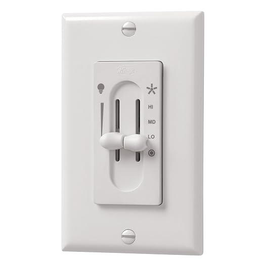
But still ANOTHER way is for the speed control to be built into the control module which gets installed into the wall switch box. Sometimes its a single button, each press of which cycles through the various preset speed settings; sometimes it's a row of buttons (Low/Medium/High, or similar); sometimes its a slider; sometimes it's a rotary knob... I've seen several variations on the basic theme. These designs are probably not as popular as they once were, now that cheap wireless control is so ubiquitous; but that doesn't mean they do not (or did not) exist.

HOWEVER...This also might exceed the "fill limit" for that single-gang box.
Huh? How would the fill limit be exceeded by adding a wire nut to 2 wires that already existed in the box in the first place. You have no idea what you're talking about!

Do additional wire nuts not take up additional space? Is that additional space consumption not figured into the official fill limits? If not, that seems a rather obvious oversight. In any event, you will hopefully recall that I said "might" -- as in, "not sure"; as in, "something to check on just in case it could be a problem". I never claimed that it WOULD exceed the official fill limit.

Besides, notwithstanding any/all legal considerations, IF that was indeed a duplex switch retrofitted into a single-gang box (which we now know it was not; but that is beside the point), said box would already be fuller than it was originally intended to be. Given that, the additional wire nut just MIGHT turn out to be the straw that breaks the camel's back in terms of even being able to make it all fit and get the switch plate back on neatly. So, given the apparent situation, a note of caution was perfectly appropriate.


2ManyProjects

Well-known member
Joined
Jul 18, 2013
Messages
757
By all my outlets I mean all my outlets in my bedroom. This includes the top and bottom outlet of each outlet fixture. Every outlet in my bedroom is controlled by one switch.

Well, that's unfortunate -- and pretty damn dumb in a bedroom: For one thing, it leaves you no good place to plug in an electric alarm clock.

The first switch controls a ceiling mounted light (which will soon the light that is built-in with the fan).

The second switch controls all the outlets in my bedroom like mentioned above.

By two switches I mean, 2 single switches in a double gang box. I have a picture to help you out further.

OK, this helps clarify the situation significantly. And indeed, things might not be not quite as bad as they initially seemed.

OTOH, they are clearly not great, either...

Since taking this picture I've seem to do something where the lights/outlets won't even come on. I tried turning the breaker switch on and as soon as I do that it trips and the switch goes in the middle.

By "the switch goes in the middle", I am presuming that you mean the toggle handle on the circuit breaker, NOT the wall switch itself -- correct?

From here, I can only guess; but I strongly suspect that "pattenp" is correct, and when you pulled those switches out from the wall, at least one of the connections was compromised.

Again, I can't be certain; but judging from the photo, it looks like you've got a mix of "back stab" and traditional "wire under screw" connections. The former are notorious for being flaky & unreliable, especially after they've aged a bit. It also looks like at least the red wire leading to the left-hand switch is not fully tightened down; but again, I can't be certain from the photo.

I would suggest that the first thing you do is re-make those connections, keeping all the wires going to all the same places (electrically), but avoiding the "back-stab" ports entirely. This will likely require making up some short pigtails using wire nuts, as it is not "kosher" to put more than one wire under one screw head. Be sure to use the same color and AWG for those pigtails as whatever you're connecting to. Your existing wire appears to be (and probably is) AWG 14. So go buy yourself a foot or two of 14/3 NM-B (commonly called "Romex") cable at your local hardware (or big box) store, strip off the outer jacket (being careful to not damage the insulation on the individual conductors), and you'll now have plenty of raw stock to make the pigtails. This will cost you less than a dollar; spend another half a buck on a small handful of appropriately sized wire nuts.

Work on one "corner" of each switch at a time, so that you can avoid getting confused as to which wire goes where. Never tie different-color wires together via either a wire nut or a screw terminal (yes, there are SOME situations where mixing colors can be appropriate; this isn't one of them). When you're done with this little chore, everything SHOULD again work like it used to, and you can move on to making the desired modifications.

Unfortunately, that mish-mash of connection techniques is not the only weirdness going on in that box. Moving on...

I do know what I did since I didn't disconnect any wires. I simply pulled the switches out so I could take a picture.

You "do" know what you did, or you "do not" know what you did?

There seems to be 4 romex wires/bundles/whatever behind the gangbox.

That seems to be confirmed by the four Neutrals (white wires) bound together. The connector they used to make that connection is somewhat unusual, but probably not a problem. More interesting is the wire count itself, AND the fact that you apparently already have some 3-conductor (plus ground) cable in there, as evidenced by the red wire. There could be several different reasons for that. Are there any OTHER switches (such as, perhaps, across the room) which also control EITHER the ceiling light or the outlets? If so, that could possibly tell us a lot.

In the meantime, pending that answer, here is the typical run-down on what you PROBABLY have in that box...

For each neutral you ALSO have one "Hot" (probably black; but see below) wire, plus one bare copper "equipment ground" conductor. The grounds should be all tied together, AND to the green screw terminal on each switch. All the Neutrals (white wires) should also be tied together (as shown in the pic; so leave that alone). All switching occurs ONLY on the "Hot" legs (usually, but NOT always, the black wire) of each circuit.

One black/white/bare combo is undoubtedly the incoming power feed to the box, which in turn is fed (perhaps indirectly) from the circuit breaker.

A second set of wires should lead to the ceiling fixture. This will PROBABLY be another black/white/bare combo. But it just MIGHT be a four-wire (black/red/white/bare) combo -- and if it is, this could possibly make your future ceiling fan installation easier.

The outlets will be fed by yet another set of wires. In this case, I'm going to wager (but only quite modestly) that this is where that 14/3 (the black/red/white/bare combo) is going.

That leaves one set of wires unaccounted for. The most likely explanation is that something else (possibly outside of that room) is ALSO daisy-chained off that same circuit. Now that the breaker for this circuit is "Off", is there anything else around the house which suddenly isn't working?

I do now know why,

What, exactly, do you now know?

I would think that even if the outlets were controlled by a switch they all would be in a series or something, but then again I don't know much.

There are a couple different ways this COULD be done. (And BTW, the correct term is "daisy-chained"; a "series" connection is something else entirely, and not suitable for this application.)

Given the ambiguity surrounding that red wire, the next step should be to pull the switch plates off all the duplex outlets, and CAREFULLY pull the outlets just far enough out of the boxes to see what wires (particularly what COLOR wires) attach to them, and where. Beware of more crappy "back stabbed" connections as you do this.

I half suspect that you're going to find at least SOME red wires in those boxes. If so, they may or may not be (but probably are) connected to the outlets. More importantly, if there is a red wire, there will near-certainly ALSO be a black wire. And if this is the case, then it will near-certainly be very easy to convert those outlets to what "justsam" calls "Half Hot" -- i.e., one socket switched, the other live 24/7. And if THAT is the case, this is the route I would strongly suggest you go. The "always live" outlets will give you places to plug in things like alarm clocks, TVs, etc.; and having at least SOME switched outlets in the room will likely also be quite useful. (Do you REALLY want to have to turn on a large overhead light just to walk into the room? More typically, a smallish table lamp is used for this purpose, especially in a bedroom, where you generally want to keep things "mellow", so to speak.)

Also, the light switch has a black wire that goes into the outlet switch, I do not know why.

Most likely to feed power from one circuit to the other. But why BOTH terminals on the right-hand switch have black wires feeding back into the box is still a bit of a mystery. Typically, only one wire would connect to each of those terminals; with MAYBE a second wire on one of them, if it were passing power to another circuit. This MIGHT be explained by having two separate wire runs to your outlets (each one feeding perhaps half the outlets); but at this point, I'm just not sure.

Lastly, there is a red wire that goes to the light switch. I also don't know why.

Ooops! I missed this on my first read-through. OK, since you have identified that switch as the one controlling the ceiling fixture, you can probably forget what I just said about checking all those outlet boxes; odds are you are NOT going to find any red wires there (tho' it certainly couldn't hurt to confirm this; so I'll leave the instructions intact).

The (potentially) good news is, you MIGHT already be wired for the ceiling fan, and not have to pull any new wire when you go to install that. To confirm this, you're going to have to pull down that ceiling fixture, and check it (and its box) for "what color wires go where". But be aware that, even if you "got lucky" in this respect, if you intend to mount a fan to the existing ceiling box, there are some serious requirements in terms of how that box is physically mounted to the building's structure, as well as for the box itself. You do NOT want a 50+ lb. fan falling on top of you in the middle of the night!


wyliesdiesels

Well-known member
Joined
Aug 14, 2012
Messages
20,054
Location
Modesto, CA
....The connector they used to make that connection is somewhat unusual, but probably not a problem.

Really? This confirms to me, along with other things you've said, that u haven't done much of any electrical and you're definitely NOT an electrician! Do u even have a code book?? Apparently not judging by your comments such as the one about fill limit....I would suggest u get a code book before spouting off more 'mights' 'maybes' and 'unsures'. Its obvious that youre guessing at a lot of this when it comes to codes:

Do additional wire nuts not take up additional space? Is that additional space consumption not figured into the official fill limits? If not, that seems a rather obvious oversight. In any event, you will hopefully recall that I said "might" -- as in, "not sure"; as in, "something to check on just in case it could be a problem". I never claimed that it WOULD exceed the official fill limit.[/b]

People dont want maybes. They want definitive answers from people who have real world experience!

Have a good day! I will no longer be reading your BOOKS.....
 

2ManyProjects

Well-known member
Joined
Jul 18, 2013
Messages
757
Really? This confirms to me, along with other things you've said, that u haven't done much of any electrical and you're definitely NOT an electrician!

Still more Straw Man Arguments? :rolleyes:

Please cite exactly where & when I claimed to be an electrician.

More to the point, please cite where in the ToS for Garage Journal it states one must be a licensed electrician to participate in these Forums?

Have a good day! I will no longer be reading your BOOKS.....

Good. Then perhaps we can all be free from your juvenile tantrums.

 
To avoid these ads, REGISTER NOW!
OP
M

maximus20895

Active member
Joined
Aug 3, 2012
Messages
43
I opened up the 2 gang box where the switches were and I pushed some wires in the back connectors. As of now, everything is working as far as the electricity goes. I still need to solve my original problem of bypassing the switch on all the outlets. I still don't exactly know how to do that quite yet.

Yes, I don't know why an electrician would make every single outlet connected to the switch especially in a bedroom, doesn't make sense to me at all hence why I am trying to solve that issue.

By the switch in the middle I meant on the breaker. Yes, it was a loose wire on one of the switches. Like I previously stated up above I have electricity again!

I want to be able to control the ceiling fan light with one switch and the fan with the other. I want exactly zero outlets controlled via a switch and want all of them on at all times. Just my preference :)

I'm almost positive the red wire it up where the ceiling light is. I asked someone who I went over my house when I was buying it if the second switch is for the fan and he said yes. I have also taken some outlet covers off and there is not a red wire in them.

As of now I would like to bypass the switch for all the outlets. Do I just connect the black wires that are connected to the switch to a wire nut besides the one that is connected to the other switch as well or what?

Thanks!
 

pattenp

Well-known member
Joined
Jun 4, 2008
Messages
10,175
Location
Virginia - USA
The only thing I can say is to get the outlets off the switch is to remove the wires from the switch that's controlling the outlets and wire nut them all together with one wire nut. Be sure to use a wire nut sized to hold the 4 of what ever size the wire is. I can't offer any help on using the switch for the fan without knowing exactly what wire feeds what. If you leave the switch in place just leave the ground wire connected to it.

Edit: The one wire that looks like its looped around the terminal will need to be cut, so you'll have 4 ends to put in the wire nut. Hopefully I'm talking about the correct switch.
 
Last edited:

zmaxmotorsports

Well-known member
Joined
Jan 11, 2013
Messages
11,948
Location
South of omaha
I opened up the 2 gang box where the switches were and I pushed some wires in the back connectors. As of now, everything is working as far as the electricity goes. I still need to solve my original problem of bypassing the switch on all the outlets. I still don't exactly know how to do that quite yet.

Yes, I don't know why an electrician would make every single outlet connected to the switch especially in a bedroom, doesn't make sense to me at all hence why I am trying to solve that issue.

By the switch in the middle I meant on the breaker. Yes, it was a loose wire on one of the switches. Like I previously stated up above I have electricity again!

I want to be able to control the ceiling fan light with one switch and the fan with the other. I want exactly zero outlets controlled via a switch and want all of them on at all times. Just my preference :)

I'm almost positive the red wire it up where the ceiling light is. I asked someone who I went over my house when I was buying it if the second switch is for the fan and he said yes. I have also taken some outlet covers off and there is not a red wire in them.

As of now I would like to bypass the switch for all the outlets. Do I just connect the black wires that are connected to the switch to a wire nut besides the one that is connected to the other switch as well or what?

Thanks!
Where are you located?
 
OP
M

maximus20895

Active member
Joined
Aug 3, 2012
Messages
43
Which wire is the one that looks like it's looped around the terminal?

For the wire that is attached to the left switch to the right switch, leave it connected to the left switch (the light) and take it off the right switch (currently outlets) and connect it with the other wires in the wire nut?

Thanks

Under "normal" conditions, how does someone connect a light from the fan to one switch and the fan to the other?

Thanks again :)
 

zmaxmotorsports

Well-known member
Joined
Jan 11, 2013
Messages
11,948
Location
South of omaha
How close are you to nebraska?
If youre within a couple hrs of here Id drive over and help you with it,youll have to supply lunch and the mountain dew.
If youre farther than that somebody else might need to volunteer for the operation.
Ive got 30 plus years of wiring and plumbing under my belt,but sometimes its just easier to explain things by showing how to do it first hand.:D
 

pattenp

Well-known member
Joined
Jun 4, 2008
Messages
10,175
Location
Virginia - USA
I talking about the switch on the right side of the picture. On my screen the wire looks like it's blue, but it is the wire that goes from the left switch to the upper screw on the right switch. The wire looks like it is looped around the screw on the right switch. Thats the wire I'm saying to cut to have 2 ends. All the wires less the ground from the right switch will be connected together with a wire nut. This is to just get the outlets off the switch. I don't know if you can leave out the wire running between the switches because I don't know where the power source comes from. The power could be coming from left to right or right to left. You need to use a volt meter to figure out what wire is hot all the time in the switch box.

Edit: You really need someone to come to your house to figure it out. It is near impossible to figure out with out being there to test with a meter and trace the wire as what can be used to switch a fan. To use that switch for the fan may require another wire to be run to control it separately from the light.
 
Last edited:

2ManyProjects

Well-known member
Joined
Jul 18, 2013
Messages
757
I opened up the 2 gang box where the switches were and I pushed some wires in the back connectors. As of now, everything is working as far as the electricity goes.

Glad to hear that you're back up & running. But DO heed what I said above about re-making those connections. As long as ANY of those "back stab" connections are left in place, the reliability of the entire system is at best suspect.

I still need to solve my original problem of bypassing the switch on all the outlets. I still don't exactly know how to do that quite yet.

We'll get to that. But in the meantime, I'll point out that, at least as things appear to stand right now, you COULD side-step this whole issue by simply making a point of leaving that right-hand switch "On" 24/7. A shortish (2" or so) piece of electrical tape or similar placed over the toggle will help discourage accidental operation of the switch. Yes, this is a really "ghetto" solution; and personally, I would not want to live with it long-term. But it would undeniably be the simplest and easiest way to accomplish your stated goal of having the outlets live 24/7.

Yes, I don't know why an electrician would make every single outlet connected to the switch especially in a bedroom, doesn't make sense to me at all hence why I am trying to solve that issue.

Understood. And if it really comes down to a choice between "no switched outlets" and "all switched outlets", then I'd have to vote for the former. But I really consider neither of those extremes to be ideal.

By the switch in the middle I meant on the breaker.

OK. I figured that was very likely the case; but it's always better to be as clear as possible in one's choice of words, so as to avoid any possible misunderstanding.

Yes, it was a loose wire on one of the switches. Like I previously stated up above I have electricity again!

And until you get rid of those back-stab connections, you're likely to have more incidents of "loose wires" in the future. Even the minor expansion/contraction you routinely get from changing climatic conditions CAN cause those things to fail.

I want to be able to control the ceiling fan light with one switch and the fan with the other. I want exactly zero outlets controlled via a switch and want all of them on at all times. Just my preference :)

Understood. But I would suggest that you defer the final decision on the permanent switch configuration until you've settled on a particular fan/light/control combo. You may wind up wanting to use something like:

Hampton Bay Ceiling Fan Wall Control
Model # 9050H
http://www.homedepot.com/p/Hampton-Bay-Ceiling-Fan-Wall-Control-9050H/202801200
54514236534a75537a64594b424c4c77573241-260x260-0-0.jpg


or:

Lutron Skylark 1.5 Amp Single Pole 3-Speed Combination Fan and Light Control - White
Model # S2-LFSQH-WH
http://www.homedepot.com/p/Lutron-S...and-Light-Control-White-S2-LFSQH-WH/100059262
d5fbb4d7-019b-467b-bcfe-47d950417ce7_300.jpg


or:

Hunter All-Fan 3-Speed Fan/Light Dual-Slide Ceiling Fan Control
Model # 27182
http://www.homedepot.com/p/Hunter-A...ual-Slide-Ceiling-Fan-Control-27182/202033443
71iWTFaPy9L._SX522_.jpg


or:

Hunter 300-Watt Remote Control for Ceiling Fan and Light
Model # 27186
http://www.homedepot.com/p/Hunter-300-Watt-Remote-Control-for-Ceiling-Fan-and-Light-27186/100395279
27186.jpg


or:

Lutron Maestro 1 Amp Multi-Location 7 Speed Combination Fan and Light Control - White
Model # MA-LFQHW-WH
http://www.homedepot.com/p/Lutron-M...and-Light-Control-White-MA-LFQHW-WH/100576179
0002755723442_P321146_500X500.jpg


For that matter, while probably less likely now than it was some years ago, something similar to the above MAY even come with the fan. Either way, this would leave the second gang in that box free for something else.

I'm almost positive the red wire it up where the ceiling light is. I asked someone who I went over my house when I was buying it if the second switch is for the fan and he said yes. I have also taken some outlet covers off and there is not a red wire in them.

Given what we now know, I'm not surprised that you didn't find red wires in the outlet boxes (a pity, that). But you'll still need to confirm that the three-conductor cable leading from that left-hand switch DOES actually go up to the ceiling box (and ONLY there), before you can know what else (if anything) will be needed to install your fan. Yes, I agree that it is likely. But better to be sure.

As of now I would like to bypass the switch for all the outlets. Do I just connect the black wires that are connected to the switch to a wire nut besides the one that is connected to the other switch as well or what?

Essentially, yes.

But, as previously noted, there is just enough other "oddness" going on in that box (and, apparently, in the room in general) that I would feel more comfortable if we really KNEW exactly what was going where, before carving that statement into granite.

Which wire is the one that looks like it's looped around the terminal?

In the photo that you posted in Post #9 http://www.garagejournal.com/forum/showpost.php?p=3382171&postcount=9, it APPEARS that the wire connecting to the "top" (or farthest right, as the switch is tilted) terminal of the right-hand switch was never cut to make the connection. Instead, a short chunk of the insulation was stripped off mid-wire, then that short exposed piece of the wire was "looped around" the screw terminal. This technique is a shortcut which is sometimes used when daisy-chaining a series of devices together on one circuit. I believe it's "legal" (someone with a code book handy can confirm/deny); but it's arguably not what I would call "Best Practice".

In any event, with only that one photo to go on, neither "pattenp" nor myself can be absolutely certain that this is actually the case; but that's how it APPEARS to be. If so, then that wire will need to be cut (and probably a bit more insulation stripped off) in order to make it into two individual bare "ends" before it can be connected to other wires via a wire-nut.

For the wire that is attached to the left switch to the right switch, leave it connected to the left switch (the light) and take it off the right switch (currently outlets) and connect it with the other wires in the wire nut?

IF we are all guessing correctly, yes.

However... Given that everything is again working "as it should" (at least vis-a-vis the admittedly questionable decision someone made to make ALL the outlets switched), I would suggest that you NOT bother with this until and unless you are ready to install the fan. For now, even the "electrical tape kludge" (distasteful as it might seem) will hold you. Then, once you have finally noodled out ALL the details of the fan installation (including confirming that the ceiling box itself and it's attachment to the framing are both up to snuff), you (or someone you hire) can do everything at once, and do it really right. Until then, there is really little or no point in screwing around with the wiring.

Under "normal" conditions, how does someone connect a light from the fan to one switch and the fan to the other?

As implied by those links & pictures above, under "normal" conditions, one does not do what you describe at all; so the "how" is irrelevant.


I don't know if you can leave out the wire running between the switches because I don't know where the power source comes from. The power could be coming from left to right or right to left. You need to use a volt meter to figure out what wire is hot all the time in the switch box.

I agree that would be the best approach; but if he just ties all the blacks leading to that right-hand switch together, it effectively becomes a moot point. Depending on parts of the existing situation we cannot know, that MAY result in one more (black) wire being connected under that big wire nut than is absolutely necessary; but I don't currently see how it would actually hurt anything.

Edit: You really need someone to come to your house to figure it out. It is near impossible to figure out with out being there to test with a meter and trace the wire as what can be used to switch a fan. To use that switch for the fan may require another wire to be run to control it separately from the light.

I am somewhat of two minds on this one.

I also tend to agree with some here who have opined that bypassing a switch is SUCH a simple thing to do that "maximus20895" apparently still being confused about it is worrisome. But there has also been quite a bit of distracting and off-point **** posted in this thread which might be part of what is fostering that confusion. So I'm inclined to cut him a bit of slack, and suggest that AFTER he has had a chance to digest all the comments made thus far, he can indeed figure it out.


zcar751

Well-known member
Joined
Apr 15, 2013
Messages
837
Location
Knoxville, TN
As to why it was wired that way don't assume it was wire to be used as a bed room. Original owner may have had it as a project room were he wanted to be able to turn off all the outlets.

Do you have more than one switch in that room to control the lights?

Where in Tennessee? If your close to Knoxville I may be able to help.
 
Last edited:

Milton Shaw

Well-known member
Joined
Feb 11, 2011
Messages
4,845
The switch on the right, the black wire backstabbed on the bottom terminal could be the wire to the outlets. If that wire was put on the other terminal it would be hot all the time. That might be where the electician made one mistake. The non used screws should be tightened down to make them less likely to short against something else. Back stabbed outlets and switches are a fire hazard if the circuit is close to capacity, they will get hot. Also don't like the neutral connector as it is a light duty connection also.
 
OP
M

maximus20895

Active member
Joined
Aug 3, 2012
Messages
43
Glad to hear that you're back up & running. But DO heed what I said above about re-making those connections. As long as ANY of those "back stab" connections are left in place, the reliability of the entire system is at best suspect.

Yes, I plan to remove the backstab connections, I just wanted to temporarily fix the issue first as I'm going to remove some of the wires when I leave the outlets on 24/7.


And until you get rid of those back-stab connections, you're likely to have more incidents of "loose wires" in the future. Even the minor expansion/contraction you routinely get from changing climatic conditions CAN cause those things to fail.

I'll fix those soon. This isn't the first time I've heard that the backstab connections are not very reliable.


Understood. But I would suggest that you defer the final decision on the permanent switch configuration until you've settled on a particular fan/light/control combo. You may wind up wanting to use something like:


For that matter, while probably less likely now than it was some years ago, something similar to the above MAY even come with the fan. Either way, this would leave the second gang in that box free for something else.

I just like the setup with one switch does the light and the other does the fan.


In the photo that you posted in Post #9 http://www.garagejournal.com/forum/showpost.php?p=3382171&postcount=9, it APPEARS that the wire connecting to the "top" (or farthest right, as the switch is tilted) terminal of the right-hand switch was never cut to make the connection. Instead, a short chunk of the insulation was stripped off mid-wire, then that short exposed piece of the wire was "looped around" the screw terminal. This technique is a shortcut which is sometimes used when daisy-chaining a series of devices together on one circuit. I believe it's "legal" (someone with a code book handy can confirm/deny); but it's arguably not what I would call "Best Practice".

In any event, with only that one photo to go on, neither "pattenp" nor myself can be absolutely certain that this is actually the case; but that's how it APPEARS to be. If so, then that wire will need to be cut (and probably a bit more insulation stripped off) in order to make it into two individual bare "ends" before it can be connected to other wires via a wire-nut.


IF we are all guessing correctly, yes.
However... Given that everything is again working "as it should" (at least vis-a-vis the admittedly questionable decision someone made to make ALL the outlets switched), I would suggest that you NOT bother with this until and unless you are ready to install the fan. For now, even the "electrical tape kludge" (distasteful as it might seem) will hold you. Then, once you have finally noodled out ALL the details of the fan installation (including confirming that the ceiling box itself and it's attachment to the framing are both up to snuff), you (or someone you hire) can do everything at once, and do it really right. Until then, there is really little or no point in screwing around with the wiring.

I'm buying the fan in the next week or so if that amounts to anything.


As implied by those links & pictures above, under "normal" conditions, one does not do what you describe at all; so the "how" is irrelevant.


I am somewhat of two minds on this one.

I also tend to agree with some here who have opined that bypassing a switch is SUCH a simple thing to do that "maximus20895" apparently still being confused about it is worrisome. But there has also been quite a bit of distracting and off-point **** posted in this thread which might be part of what is fostering that confusion. So I'm inclined to cut him a bit of slack, and suggest that AFTER he has had a chance to digest all the comments made thus far, he can indeed figure it out.
 
OP
M

maximus20895

Active member
Joined
Aug 3, 2012
Messages
43
As to why it was wired that way don't assume it was wire to be used as a bed room. Original owner may have had it as a project room were he wanted to be able to turn off all the outlets.

Do you have more than one switch in that room to control the lights?

Where in Tennessee? If your close to Knoxville I may be able to help.

The house was finished being build about a month ago so I'm the first person who lived here.

There is only one switch to control the lights.

I live in Farragut.
 

Zippercat

Well-known member
Joined
Jul 13, 2013
Messages
828
Location
TN
Seems to me that this is something you can raise as a complaint to the builder. No way a bedroom should be wired this way. The builder should get their electrician out there to get it right. Be sure to tell the builder that the switch connection was so loose that by simply opening up the box your breaker was tripping too.
 
OP
M

maximus20895

Active member
Joined
Aug 3, 2012
Messages
43
Seems to me that this is something you can raise as a complaint to the builder. No way a bedroom should be wired this way. The builder should get their electrician out there to get it right. Be sure to tell the builder that the switch connection was so loose that by simply opening up the box your breaker was tripping too.

I have another bedroom that the layout is the same etc and the outlets are on 24/7 and the other switch is wired for a future fan. It's like a different electrician wired the other room. The gang boxes in the room I'm trying to fix are ridiculous, not using the right screws, holes too big so the outlets are moving back and forth when I plug something in them, just horrible. I'm starting to tell them to fix it.
 

brewchief

Well-known member
Joined
Sep 20, 2008
Messages
2,370
Location
Michigan
Which switch controls the light and which controls the outlets right now?

I think I might know whats going on.
 
OP
M

maximus20895

Active member
Joined
Aug 3, 2012
Messages
43
The left one controls the lights where as the right one (the one with a bunch of black wires and NOT the red wire) is the outlets.

Thanks :)
 

2ManyProjects

Well-known member
Joined
Jul 18, 2013
Messages
757
The house was finished being build about a month ago so I'm the first person who lived here.

OK, either I missed this previously, or this is new information. Either way, it changes the picture somewhat -- particularly in terms of who should be responsible for fixing this mess.

Seems to me that this is something you can raise as a complaint to the builder. No way a bedroom should be wired this way.

I agree.

I'm going to climb out on a limb here and guess that this is a tract house put up by a high-volume "developer", who probably hires and fires subs on a near-daily basis in the never-ending quest to squeeze out every last nickel of profit from the operation, and whose first priority is probably "get it done fast, for no money". Hell, given the hack work most recently described by "maximus20895", I would not be shocked if he (or some of his subs) were even cruising by the local Home Depot each morning and picking up undocumented day workers for at least some of this sort of stuff.

The builder should get their electrician out there to get it right.

Well, they should get AN electrician out there. But given the nonsense this builder's subs have already wrought, I daresay I would NOT want the same sub(s) that did the initial wiring.

And if/when the builder does send someone out to re-do this mess, either "maximus20895" himself, or (better) someone well-qualified whom he trusts, should also be there watching this guy like a hawk, and not hesitating to INSIST that anything wrong or marginal that they see is corrected on the spot. If the sub (or the builder) doesn't like that, tough. It is the builder's responsibility to deliver the house in proper "fit to use" condition -- and neither flaky electrical connections nor a bedroom with NO unswitched outlets meets that criterium, IMCO.

Be sure to tell the builder that the switch connection was so loose that by simply opening up the box your breaker was tripping too.

Again, I agree. This is not just a convenience/"suitability to purpose" issue; it is a matter of fundamental safety.


I have another bedroom that the layout is the same etc and the outlets are on 24/7 and the other switch is wired for a future fan. It's like a different electrician wired the other room.

So what does the second switch control in THAT room?

The gang boxes in the room I'm trying to fix are ridiculous, not using the right screws, holes too big so the outlets are moving back and forth when I plug something in them, just horrible. I'm starting to tell them to fix it.

Be calm. Be polite. But also be absolutely FIRM. Have you signed off on the punch list yet?

 
Last edited:

brewchief

Well-known member
Joined
Sep 20, 2008
Messages
2,370
Location
Michigan
Based on what I see one of the black wires on the bottom of the switch on the right should be your plugs, the other one of the black wires on the bottom should be part of the 14-3 cable that has the red wire in it.

The black wire that is part of the 14-3 cable should be the wire that controls the fan, you should find it in the ceiling fixture wire nutted when you go to install the fan.

Move the other black wire to the other side of the switch and I bet your plugs work properly.

I would get rid of the back stabbed connections and pigtail as needed as well at this point.

If this isn't clear enough I can provide better detail tonight after work.
 
To avoid these ads, REGISTER NOW!
Top Bottom