To avoid these ads, REGISTER NOW!

Relay circuit tester DIY

signcrafter

Well-known member
Joined
May 9, 2012
Messages
12,525
I've been wanting to build one of these, http://www.cal-vantools.com/p-167-relay-circuit-diagnostic-tool.aspx for some time now and have asked multiple questions on here about various parts of doing this. Everything from wiring up LEDs to resistors to diodes, etc. This is one of those things I won't use often but it will come in handy from time to time. I've been playing around with electronics and lately and learning what I can. Ordered a bunch of parts from ebay and today had some time to get a start on it. There is a video in the link above as to how it works.

Here is some of the parts and pieces I've been gathering.
IMG_20140320_120716_381_zpsc4f1b115.jpg

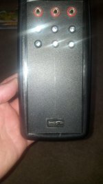
Then I got out my radio shack electrical kit out to figure out the wiring. When you hook the tester up to the car's battery both the red and green LEDs come on. Then when you plug the relay adapter into the relay socket if a certain pin sees 12volts the red LED stays lit and the green LED goes out. If it sees ground the green LED stays on and the red LED goes out. Pins 85, 86, and 30 all have a set of LEDs to show what each wire is seeing. This tells you right away if you have power and ground on 85 and 86 coil side. Then tells you if 30 is power or ground.

IMG_20140320_124514_891_zpsc0ea7ea7.jpg

Laid out where I wanted things on the case and drilled the holes.
IMG_20140320_130329_647_zpsa1c3ff3e.jpg

Installed the 4mm test ports and the LEDs in their holders.
IMG_20140320_131219_484_zps5fe94e18.jpg

Soldered it all together. The wiring coming from the relay socket to the tester will go to the 4mm test ports first for pins 85, 86, and 30. Then it goes threw a diode to the LEDs and then a resistor. The red LEDs light up when the incoming wire is 12 volts so the resistors from the red LEDs go to ground from the car battery. Then the Green LEDs light up when they see ground coming in from the relay socket so their resistors go to 12 volt +. I don't have these hooked up yet but you can see where I soldered the resistors together.
IMG_20140320_131219_484_zps5fe94e18.jpg

This is what you see when you hook the tester up to the car's battery. All the LEDs come on.
IMG_20140320_155547_980_zps697bebb9.jpg

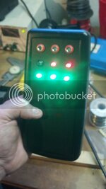
Then when you plug the tester into the relay socket if pin 85 sees ground it shuts the red LED off and the green stays lit..
IMG_20140320_155642_100_zpse3340c05.jpg

If it sees 12 volts the green goes out and red stays on.
IMG_20140320_155627_624_zpsa8ded857.jpg

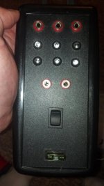
This is what it will look like when done.
IMG_20140320_124848_762_zps22d0e49a.jpg

I'm going to order a switch that is momentary/off/on. This will allow you to apply power to pin 87 in order to activate different things. Also thinking about putting in a fuse holder so I can make a loop of wire and use an amp clamp with it so you can see the draw.
 
To avoid these ads, REGISTER NOW!

bareass172

Well-known member
Joined
Aug 5, 2012
Messages
817
Location
N'awlins
Neat project! What are you using for all your connections? Obviously the battery connection is simple, but what about plugging into relays and such? Looking at your parts, are you going to dismantle some relays?
 
OP
S

signcrafter

Well-known member
Joined
May 9, 2012
Messages
12,525
Neat project! What are you using for all your connections? Obviously the battery connection is simple, but what about plugging into relays and such? Looking at your parts, are you going to dismantle some relays?

The battery connector will just be a wire with alligator clips on it. For plugging into the relay sockets I plan on doing as you thought and making some adapters out of junkyard relays. I haven't exactly figured out the best way yet but right now I'm thinking to take them apart and then "gut" them except the spade terminals sticking threw the bottom. Solder some wires onto the terminals and then put the top back on the relay with the wires sticking out. Then pour some fiberglass resin in the relay to hold everything in place, think this is called "potting" or something. Thinking about finding some molex type plugs off cars from the junkyard to hook the different relay adapters up to the tester.
 
OP
S

signcrafter

Well-known member
Joined
May 9, 2012
Messages
12,525
Mine came with 2 books also. I did some of the projects in the books but I mostly use it for stuff like this. I'm pretty dense so it takes me longer to understand things and I have to be able to see it! When I got it I had no clue about LEDs and resistors and capacitors and diodes and all that stuff. Still don't know a lot but can at least work my way through hooking some LEDs up now. Think it was only like 60-70 bucks so not to bad.
 
OP
S

signcrafter

Well-known member
Joined
May 9, 2012
Messages
12,525
Where's the relay socket?

Relay socket? This won't test relays, it's made to test the circuit up to the relay. It tests for 12v and ground on the coil side and then tests for 12v or ground coming into the relay. Then allows you to jump that to the relay "output". Pretty much testing the whole circuit from the relay socket. If it all works then your relay is most likely bad.

If you watch the video I linked to in the first post it shows exactly how this works.
 

my58

Well-known member
Joined
Apr 12, 2005
Messages
238
Location
Ventura County California
SignCrafter,

Great project. Reading your post, it seems like you really enjoy electronics and learning more about it. The old Radio shack "breadboard" component kit was the standard hobbyist learning tool for many years.

If you have not yet looked at arduino boards, I would like to suggest it to you. It opens up an entire new world of modern electronics to those of us who have a love of electronics. The link http://www.arduino.cc/ is just the basics, if you Google arduino you will find a huge world of arduino projects and enthusiasts.

Thanks again for posting your electronic project.
 
OP
S

signcrafter

Well-known member
Joined
May 9, 2012
Messages
12,525
SignCrafter,

Great project. Reading your post, it seems like you really enjoy electronics and learning more about it. The old Radio shack "breadboard" component kit was the standard hobbyist learning tool for many years.

If you have not yet looked at arduino boards, I would like to suggest it to you. It opens up an entire new world of modern electronics to those of us who have a love of electronics. The link http://www.arduino.cc/ is just the basics, if you Google arduino you will find a huge world of arduino projects and enthusiasts.

Thanks again for posting your electronic project.

Wow those look fun to play around with. I'm still learning about the different electrical components and how to put them together. Adding software into the mix would be a whole nother level above my head!

I do like to play around and learn about electronics, among many other things. And making useful projects gives me a reason to play around.

In for a purchase :)

Not sure there will ever be a production run! Plus there is a company that makes and sells these already. I can give you all the info I've researched and what parts I'm using if you're interested in building your own.
 

bareass172

Well-known member
Joined
Aug 5, 2012
Messages
817
Location
N'awlins
I just posted this into another thread, it might help you also. You could buy disconnects like these perhaps:

http://www.ebay.com/itm/10-Kits-2-P...uto-Set-/360887274163?&_trksid=p2056016.l4276

To make changing ends fast and easy. I think you're right on target for re-using the old relays, it's likely what I'd do too. FYI, you're right, it is called "potting". ;)

I also forgot to mention in my last post that I am also envious of your breadboard! I have an old simple board that got my dad through electrical engineering in college, and I just tie it to my adjustable benchtop supply. Do you have a model number or something for that BB? I've actually never seen one before and I dig it.

I'm very interested to see your progress, and would love to see a final schematic of how you did this. Thanks for taking the time.
 

sdguy55

Well-known member
Joined
Jan 26, 2012
Messages
2,424
Location
Pierre, SD
Wow those look fun to play around with. I'm still learning about the different electrical components and how to put them together. Adding software into the mix would be a whole nother level above my head!

I do like to play around and learn about electronics, among many other things. And making useful projects gives me a reason to play around.


Not sure there will ever be a production run! Plus there is a company that makes and sells these already. I can give you all the info I've researched and what parts I'm using if you're interested in building your own.

No I'm not interested in the info, just want it in my hands working haha
 
OP
S

signcrafter

Well-known member
Joined
May 9, 2012
Messages
12,525
We have 2 radio shacks in town, used to have 4-5 of them back in the day. One is mostly a cell phone store. The other is an old school one that still has all the electrical stuff. When I bought the kit I stopped at the cell phone one and they didn't have a clue what I was talking about. Pointed me to a computer and told me I could order it from online and have it shipped to the store. I went across town and they had it in stock.

Here is another thread from me asking about a diode, http://www.garagejournal.com/forum/showthread.php?t=227798&highlight=relay. In the first post I have a picture of the wiring and also a link to the patent from cal-van that actually makes the tool which also shows the wiring.
 
OP
S

signcrafter

Well-known member
Joined
May 9, 2012
Messages
12,525
Not to much progress to report. I ordered some more parts off ebay so waiting for them to come over on the boat. I ordered a switch that is ON-OFF-(ON). This switch will jump pin 30 to 87 to activate whatever the relay controls. The switch I ordered will allow me to either "pulse" the device or have it constant on. Just like the option of momentary or constant on. Say you are testing a fuel pump and just want to quick on/off so you hit the momentary side of the switch. Or if you want to run the pump constant you can hit the constant side of the switch. Might not be needed but I thought it may come in handy.

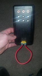
I also bought some fuse holders that are "panel mount. This will allow me to have some fused protection when powering up things. Technically if there is power at pin 30 it should already be fused but it will be a back up and serve another purpose also. The second purpose is a place to hook up a loop in order to have a place to hook an amp clamp. To do this I will just take the fuse out of the holder and then insert one of these, http://www.amazon.com/dp/B001TCXOTW/?tag=atomicindus08-20. On the adapter I will hook another fuse holder in a loop. This will still complete the circuit and let me hook up amp clamp.

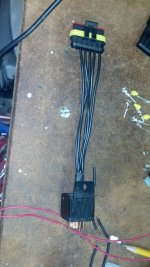
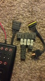
I did get a chance to make up one of the relay adapters. I ordered some 6 pin weatherpack connectors off ebay. The 5 pin ones would have been nicer being they are round instead of flat but they are a lot more expensive then the 6 pin for some reason. This will let me make up the adapters for different relays and then switch them out to hook up to the tester. I just cut up a spare relay and gutted it. Then soldered some wires onto the tabs and then put the weatherpack connector on the other end. This is just the standard bosch 5 pin relay and will make up other ones once I get to the junkyard and get some more relays from different vehicles.

IMG_20140330_202151_323.jpg

IMG_20140330_203934_554.jpg

That's it for now. I also have the 2 pin weather pack to make up the power going into the tester. This will allow me to hook up to my lighter plug or alligator clips I made up the other day in this thread, http://www.garagejournal.com/forum/showthread.php?t=242545.
 
To avoid these ads, REGISTER NOW!

bareass172

Well-known member
Joined
Aug 5, 2012
Messages
817
Location
N'awlins
They must make 2 styles of 5 pin, because I've only seen these:
http://www.ebay.com/itm/14086220169...m=&sspagename=ADME:X:eRTM:MOTORS:1123&vxp=mtr

I do know that they make 2 styles of 6 pin, because I've seen the flat 6 and the 2 rows of 3 styles.
In case I didn't mention it before, I use this site for connectors a lot:
http://www.jst.com/index.html

Check specs for what you need there, and then you can usually buy them at places like Digikey and Mouser.

Project looks great so far, I'm looking forward to seeing your finished schematic for how it all goes together. ;)
 

James_B

Well-known member
Joined
Jun 24, 2013
Messages
674
Location
Nova Scotia, Canada (started in Brisbane, Australi
I also forgot to mention in my last post that I am also envious of your breadboard! I have an old simple board that got my dad through electrical engineering in college, and I just tie it to my adjustable benchtop supply. Do you have a model number or something for that BB? I've actually never seen one before and I dig it.
Judging from the interest in that RS breadboard, there's the makings of a new topic just on breadboards and prototyping boards ... all the way from the simplest breadboard or equivalent to some of the newer Arduino kits.

When I was doing my electronics industry training in the early 70s, we improvised breadboards out of spring loaded electrical terminal strips (still got a couple that I use occasionally).

These days my pride and joy is a roughly 2½ foot square digital logic circuit patch board that I picked up for a pittance 20 years ago at an auction of surplus training equipment from a government technical training school.
 
OP
S

signcrafter

Well-known member
Joined
May 9, 2012
Messages
12,525
They must make 2 styles of 5 pin, because I've only seen these:
http://www.ebay.com/itm/14086220169...m=&sspagename=ADME:X:eRTM:MOTORS:1123&vxp=mtr

I do know that they make 2 styles of 6 pin, because I've seen the flat 6 and the 2 rows of 3 styles.
In case I didn't mention it before, I use this site for connectors a lot:
http://www.jst.com/index.html

Check specs for what you need there, and then you can usually buy them at places like Digikey and Mouser.

Project looks great so far, I'm looking forward to seeing your finished schematic for how it all goes together. ;)

How come you didn't post that link a week ago! When I searched ebay for "5 pin weatherpack" this is what comes up, http://www.ebay.com/sch/i.html?_odk...73.m570.l1313&_nkw=5+pin+weatherpack&_sacat=0. I would really like the round type of connectors because they would be nice to use but for the price the flat will have to do. I'll have to order some of the 5 pin flat and just switch the plug housing.

Finished schematic? That's funny. I have a few sketches on paper and my breadboard as my schematics! Also looked at the schematics for the cal-van unit and the U activate tool that I kind of took parts from each of what I liked and combined them to make my own tester.

One thing I"m not sure about is all my diodes and resistors are just "floating" around inside and some bare metal pretty close to others so I was thinking about brushing on some liquid electrical tape or something in case I drop it and the wires move around and touch. Any suggestions on that after looking at the pictures above?
 

DenisG

Well-known member
Joined
Jul 14, 2013
Messages
1,278
Location
Milwaukee
...

One thing I"m not sure about is all my diodes and resistors are just "floating" around inside and some bare metal pretty close to others so I was thinking about brushing on some liquid electrical tape or something in case I drop it and the wires move around and touch. Any suggestions on that after looking at the pictures above?

You can find "liquid electrical tape" online or at most BORGs. I've used that or clear silicone RTV on different occasions.
 

bareass172

Well-known member
Joined
Aug 5, 2012
Messages
817
Location
N'awlins
My apologies for not posting the proper link, lol. :sad:
The difference is in what you're searching for. Metripack and weatherpack are common brand names so I think it limits what you find with searches. I actually stumbled upon the "china weatherpack" connectors because of an old search I had done on Ebay that Ebay saved and displayed to me. I had been trying to find "2-pin waterproof connectors" for a motorcycle project. Remove the "2-pin" and you have a lot of options. I actually contacted one of the companies to see if they'll sell me a set of each type, 1 pin through 6 pin and 10 of each. I do enough work with these that they'll come in handy. I assume that they're not the same quality as "real" metri-pack connectors, but for what I need they'd still be ample. You're right though, the round style do look very nice. :eyecrazy:

If you have links to those other schematics you looked at, can you please post them? I'm curious how you put this together, not because I can't figure it out like you did, but because I'm too lazy to think about it myself. :dunno:

As for coating all the parts, I have used RTV silicone before also (in a bind) but the liquid electrical tape stuff would be better. Ideally you could "pot" the whole thing like you mentioned possibly doing with the relays, but that would make it impossible to make changes to later. In your shoes I would get the liquid tape SPRAY. GB and Performix both make them, it would be much easier than trying to glob the brush all over everything. Performix also makes it in a clear formula, so you could spray but still see everything.
 
OP
S

signcrafter

Well-known member
Joined
May 9, 2012
Messages
12,525
Ebay searching is a skill of it's own!

For the schematics I searched for the patents of the other two tools and also searched the **** out of them. The cal-van tool was the first one I found and liked some of the features of it. Then ran across the u activate tool while watching a scanner danner video. Here is the link to the google patent for the cal van tool https://www.google.com/patents/US83...a=X&ei=FjSqUofMBcrkyAGexoGgBA&ved=0CHkQ6AEwCA. It has their wiring schematic on it that shows how the LEDs are wired with the resistors and diodes. Also shows how the switch is wired up. The U activate tool has a generic schematic on the cover of it. Here is a some info on that tool, http://uactivate.yourdiagnostictools.com/2011/05/connections/. I'll try to get one of my sketches up of my "schematics". Just a crude drawing.

Between the two I made my own hybrid version with some features of each. Changed some things to make it how I wanted and how I thought it would work better.

I'll go with the liquid electrical tape for now and see how that works. Didn't really want to pot the whole thing and liquid tape is fairly cheap.

Thanks for all the good advice and the links to ebay items!
 
OP
S

signcrafter

Well-known member
Joined
May 9, 2012
Messages
12,525
I got some more work done on this today. I cut a slot out for the fuse holder and then epoxied it into place. This fuse holder will serve two purposes. First, it's going to be just after the pin 30 from the relay enters the tool. So this will be the power from the vehicle. Then from the fuse holder it will go to the switch. Then when you press the switch it will connect 30 and 87 and activate whatever the relay controls. I thought it would be a good idea to put a fuse in here. Probably not needed since there is no fuse in the relay when it's in the car but figured better safe then sorry. After I cut the hole out and filed the edges I roughed up the surfaces and used some plastic epoxy to mount the fuse holder to the tester.

But the main purpose of this is as a "break out" for the circuit. I can put my fuse adapter in it and make a loop to put your amp clamp around. Was one of the features I like on the U Activate tool but I didn't want a loop there all the time.

I also started to work on the wiring coming out of the tester. I made up the 5 pin harness coming out of the tester. This will plug into the different relay adapters I need to make up, so far I've just done the standard 5 pin relay. I also started on the power plug that is going to hook up to the battery. This is needed in order to operate the LEDs. I've also thought about hooking up another switch from the 12V battery input that would go to pin 87. This might come in handy if for some reason you lost power at pin 30. So you hook up the tester and see no power at pin 30 you can take power from the battery input and send it to pin 87 and activate what ever the relay controls. If the device activates then you know you have to find where you lost power on the pin 30 circuit.

IMG_20140417_133317_465.jpg

IMG_20140417_133328_156.jpg

IMG_20140417_133510_733.jpg

IMG_20140417_133516_897.jpg

IMG_20140417_134309_831.jpg

IMG_20140417_134326_433.jpg
 
OP
S

signcrafter

Well-known member
Joined
May 9, 2012
Messages
12,525
I've been working on this here and there as I get time and parts. I finally got my switch that is ON-OFF-MOMENTARY, so I can flip it one way and have constant power and flip it the other way and have momentary power. This will be nice for activating different things like fuel pumps or lights or whatever. The switch is basically just acting as the relay and connecting pin 30 and 87 to activate whatever the relay does.


IMG_20140513_132359_102.jpg

IMG_20140513_132528_101.jpg

IMG_20140513_132553_920.jpg

IMG_20140513_133035_497.jpg

I picked up some various relays the other day when I was at the junkyard and I'm going to head back to the junkyard and try to find some other relays for other vehicles. I'll just gut them like I did with the bosch 5 pin I already made and then solder on wires to the tabs and then on the other end will have a quick connect.

I still need to test it all out on a power supply but it all worked good the last time I tested it out and I just added the switch so it should be good. Then put it to work! It won't be something that I use often or much but it will come in handy. I've wanted one of the cal-van kits for a while now but was too expensive for the few times I would use it. I have about 15-20 bucks into this one and a great learning experience!
 
OP
S

signcrafter

Well-known member
Joined
May 9, 2012
Messages
12,525
Got a chance to do some bench testing today and it works great. Here's some pics.

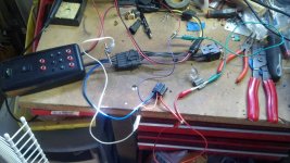
Here is my mess of wires. A simple headlight circuit with a relay socket with power on pin 86 and ground on 85 for the switch side of the relay. Pin 30 is power and 87 goes to a light bulb which also has a ground.
relay tester.jpg

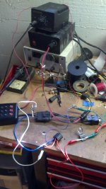
Using my plug and play setup I made I can use a lighter plug or alligator clips to power the tester up. Here is the tester plugged into a power supply.

relay tester 2.jpg

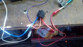
Here is the relay socket. The blue wire is pin 30 which is power coming in. Larger red wire is pin 87 that is the switched output that sends power to the bulb. Small purple wire is pin 85 and goes to ground for the switch side of the relay and the small red wire is 86 and goes to power, or in real life would be the headlight switch.

relay tester 3.jpg

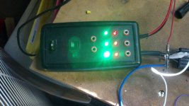
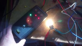
This shows the tester is powered up by the lighter plug. All LEDs light up until they see power or ground. The tester isn't plugged into the relay socket at this time.

relay tester 5.jpg

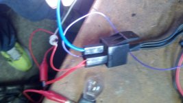
The tester relay adapter plugged in to the relay harness.

relay tester 6.jpg

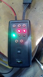
Now that it's plugged into the relay slot the first LED is green and shows pin 85 has a ground. Second LED is red and shows pin 86 has power. At this point you know the switch side of the relay is working, or at least getting power and ground like it needs to activate the relay. In real life this would mean the headlight switch is on. You could turn the switch off and pin 86 should go back to having both LEDs on since it wouldn't be getting signal. The 3rd set of LEDs shows pin 30 is getting power coming in.

relay tester 7.jpg

Finally you can activate the bulb by using the switch on the tester to connect pins 30 and 87. This switch is constant if you push it up and momentary if you push it down. So you can send steady power to the device or pulse it. This will also be handy for just activating things like a fuel pump or whatever you want that is controlled by a relay.

relay tester 9.jpg

I'm pretty happy with the results. And most importantly I used this project to learn about electronics. Before this I had never sized resistors for LEDs. Didn't know much about diodes. Learned a lot doing this. I still need to build more relay adapters for all the different types of relays out there.
 

bareass172

Well-known member
Joined
Aug 5, 2012
Messages
817
Location
N'awlins
I've really enjoyed seeing the progress and learning about it as well. This will be a project I'll knock out one of these days myself since I used a lot of relays too.

Thanks a lot of taking the time to do it, but also to post all the information.
 
OP
S

signcrafter

Well-known member
Joined
May 9, 2012
Messages
12,525
I've really enjoyed seeing the progress and learning about it as well. This will be a project I'll knock out one of these days myself since I used a lot of relays too.

Thanks a lot of taking the time to do it, but also to post all the information.

My pleasure! I try to post all my little DIY projects on here for others but also it works great as a way to collect all my thoughts. While writing posts I think of all sorts of changes and whatnot to iron out the details. And get advice and opinions from others. Didn't seem like much interest in this one but that's alright. If you need any advice on parts or whatnot when you build yours just let me know.:beer:

I'm hoping to do some on car testing sometime soon. I have a project truck that I can hook up a fuel pressure gauge to and activate the fuel pump relay. Going to try and make a video of that.
 

MatcoDave

Well-known member
Joined
Apr 9, 2014
Messages
61
Location
Cedarville NJ
mada2eqy.jpg


guqyhaze.jpg


Great build! If you're looking for something a little simpler check these out
 
OP
S

signcrafter

Well-known member
Joined
May 9, 2012
Messages
12,525
mada2eqy.jpg


guqyhaze.jpg


Great build! If you're looking for something a little simpler check these out

Thank you. I ran across those in my researching for this project. Those are pretty neat for what they are. Would come in handy for activating the devices. But I wanting something a little more in depth for testing. And also just wanted a project to learn more about electronics. The relay bypass switches don't tell you if you have a ground and 12V+ for the switch side of the relay circuit. Also doesn't give you any info if the device doesn't work with the switch. If the device doesn't work when using the bypass switch then you still have to see if you have power on pin 30. But they are another tool to have in the box and they would come in handy. I actually have thought about making some of them up but am still looking for some switches that are shallow enough to fit after gutting a relay. I pick up a handful of relays every time I go to the junkyard, they usually only charge me a buck or two for the handful. I'd like to make a set of these bypass switches and also come up with a way to make something similar to the lisle relay testers that you can plug in and still use the relay while testing.

I take it you're a matco dealer? Good to have you on the GJ!
 

MatcoDave

Well-known member
Joined
Apr 9, 2014
Messages
61
Location
Cedarville NJ
Ahh gotcha! Always fun to test and learn with projects like that. As a kid thats how i learned most of what i know now. Take it apart, see what it does and figure out how it goes back together. Yes, i'm a matco dealer and new to GJ, thanks!
 
OP
S

signcrafter

Well-known member
Joined
May 9, 2012
Messages
12,525
Yep I like to tinker with things!

It's great to have tool reps on here. Just don't let any posters get under you skin. Some guys have strong opinions on things, one being tool trucks charge way to much, etc. There have been dealers on here before that stopped posting I assume because they got tired of the same ****. Glad to have you here.:beer:
 
To avoid these ads, REGISTER NOW!
Top Bottom