signcrafter
Well-known member
- Joined
- May 9, 2012
- Messages
- 12,664
I've been wanting to build one of these, http://www.cal-vantools.com/p-167-relay-circuit-diagnostic-tool.aspx for some time now and have asked multiple questions on here about various parts of doing this. Everything from wiring up LEDs to resistors to diodes, etc. This is one of those things I won't use often but it will come in handy from time to time. I've been playing around with electronics and lately and learning what I can. Ordered a bunch of parts from ebay and today had some time to get a start on it. There is a video in the link above as to how it works.
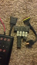
Here is some of the parts and pieces I've been gathering.

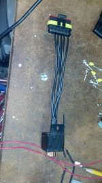
Then I got out my radio shack electrical kit out to figure out the wiring. When you hook the tester up to the car's battery both the red and green LEDs come on. Then when you plug the relay adapter into the relay socket if a certain pin sees 12volts the red LED stays lit and the green LED goes out. If it sees ground the green LED stays on and the red LED goes out. Pins 85, 86, and 30 all have a set of LEDs to show what each wire is seeing. This tells you right away if you have power and ground on 85 and 86 coil side. Then tells you if 30 is power or ground.

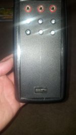
Laid out where I wanted things on the case and drilled the holes.

Installed the 4mm test ports and the LEDs in their holders.

Soldered it all together. The wiring coming from the relay socket to the tester will go to the 4mm test ports first for pins 85, 86, and 30. Then it goes threw a diode to the LEDs and then a resistor. The red LEDs light up when the incoming wire is 12 volts so the resistors from the red LEDs go to ground from the car battery. Then the Green LEDs light up when they see ground coming in from the relay socket so their resistors go to 12 volt +. I don't have these hooked up yet but you can see where I soldered the resistors together.

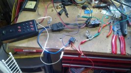
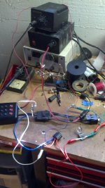
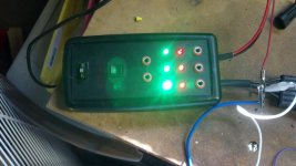
This is what you see when you hook the tester up to the car's battery. All the LEDs come on.

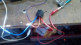
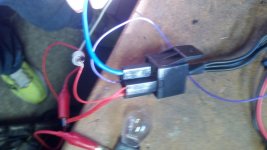
Then when you plug the tester into the relay socket if pin 85 sees ground it shuts the red LED off and the green stays lit..
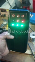
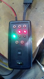
If it sees 12 volts the green goes out and red stays on.

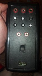
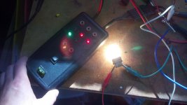
This is what it will look like when done.

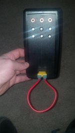
I'm going to order a switch that is momentary/off/on. This will allow you to apply power to pin 87 in order to activate different things. Also thinking about putting in a fuse holder so I can make a loop of wire and use an amp clamp with it so you can see the draw.
Here is some of the parts and pieces I've been gathering.
Then I got out my radio shack electrical kit out to figure out the wiring. When you hook the tester up to the car's battery both the red and green LEDs come on. Then when you plug the relay adapter into the relay socket if a certain pin sees 12volts the red LED stays lit and the green LED goes out. If it sees ground the green LED stays on and the red LED goes out. Pins 85, 86, and 30 all have a set of LEDs to show what each wire is seeing. This tells you right away if you have power and ground on 85 and 86 coil side. Then tells you if 30 is power or ground.
Laid out where I wanted things on the case and drilled the holes.
Installed the 4mm test ports and the LEDs in their holders.
Soldered it all together. The wiring coming from the relay socket to the tester will go to the 4mm test ports first for pins 85, 86, and 30. Then it goes threw a diode to the LEDs and then a resistor. The red LEDs light up when the incoming wire is 12 volts so the resistors from the red LEDs go to ground from the car battery. Then the Green LEDs light up when they see ground coming in from the relay socket so their resistors go to 12 volt +. I don't have these hooked up yet but you can see where I soldered the resistors together.
This is what you see when you hook the tester up to the car's battery. All the LEDs come on.
Then when you plug the tester into the relay socket if pin 85 sees ground it shuts the red LED off and the green stays lit..
If it sees 12 volts the green goes out and red stays on.
This is what it will look like when done.
I'm going to order a switch that is momentary/off/on. This will allow you to apply power to pin 87 in order to activate different things. Also thinking about putting in a fuse holder so I can make a loop of wire and use an amp clamp with it so you can see the draw.