To avoid these ads, REGISTER NOW!

320 Meter and 2 Separate 200 Amp Mains

OP
T

traumadoc2b

Well-known member
Joined
Jun 17, 2014
Messages
104
Location
Indianapolis
Phase one is complete! The POCO cut the lines at 9am today and I got to work. Had a few snags, like drilling a hole through the brick for the additional conduit (that seemed to take forever) and trying to get the 4/0 feeder into the lugs (no wonder there's a preference for 2/0 copper instead). Got my green tag from the inspector though and had the lines hooked back up and the meter reinstalled. Had power back on in the shop by about 6pm, and boy am I tired and sore. New found respect for electricians. And I even had good weather and wasn't crawling through insulation pulling cable.
 
Last edited:
To avoid these ads, REGISTER NOW!

wyliesdiesels

Well-known member
Joined
Aug 14, 2012
Messages
20,013
Location
Modesto, CA
First phase of work is tomorrow. Just started to doubt if I can use THHN to connect meter can to main, back to back. I wouldn't think that being in the enclosure would be considered a wet location. Any reassurance?

I think it would be considered damp location but i would have to look it up. I do see and have installed THHN/THWN in meter cans so i think your fine.

Phase one is complete! The POCO cut the lines at 9am today and I got to work. Had a few snags, like drilling a hole through the brick for the additional conduit (that seemed to take forever) and trying to get the 4/0 feeder into the lugs (no wonder there's a preference for 2/0 copper instead). Got my green tag from the inspector though and had the lines hooked back up and the meter reinstalled. Had power back on in the shop by about 6pm, and boy am I tired and sore. New found respect for electricians. And I even had good weather and wasn't crawling through insulation pulling cable.

Awesome!! Now which lugs are u referring to? If the lugs on the neutral bar, u can get an add on lug...
 
Last edited:
OP
T

traumadoc2b

Well-known member
Joined
Jun 17, 2014
Messages
104
Location
Indianapolis
The trouble wasn't really with the lugs, they're the correct size. The problem was getting the 4/0 wire bent to go where I wanted it to go.

Here are some photos from yesterday's work. You'll notice some stuff with the old work, including the connector and bushing that was on the SER feeder, going to the house. This is a 4/0-3, 3/0 ground cable that was shoved through a 1 1/2" connector and bushing. I couldn't get it back out, don't know how they got it in there. I eventually cut the connector, bushing, and lock nut off with a bolt cutter. Besides that, when I pulled on the ground wire, it just came out from the wall. Apparently they had it connected to the lug in the panel so that it looked right, but the other end of it was just tucked into the masonite, behind the panel. Then the old meter can wasn't screwed into the exterior wall at all. They had taken a bunch of cement and smeared it on the wall and the conduit from the lateral and going to the main panel were the only things holding the meter socket up.
 

Attachments

  • IMG_2328.jpg
    IMG_2328.jpg
    134.5 KB · Views: 49
  • IMG_2337.jpg
    IMG_2337.jpg
    126 KB · Views: 46
  • IMG_2336.jpg
    IMG_2336.jpg
    142.4 KB · Views: 52
  • IMG_2335.jpg
    IMG_2335.jpg
    123.7 KB · Views: 50
  • IMG_2334.jpg
    IMG_2334.jpg
    140.2 KB · Views: 48
  • IMG_2333.jpg
    IMG_2333.jpg
    135.5 KB · Views: 50
  • IMG_2332.jpg
    IMG_2332.jpg
    138.7 KB · Views: 55
OP
T

traumadoc2b

Well-known member
Joined
Jun 17, 2014
Messages
104
Location
Indianapolis
More pics...
 

Attachments

  • IMG_2352.jpg
    IMG_2352.jpg
    138.1 KB · Views: 70
  • IMG_2351.jpg
    IMG_2351.jpg
    132.8 KB · Views: 90
  • IMG_2350.jpg
    IMG_2350.jpg
    136.4 KB · Views: 64
  • IMG_2347.jpg
    IMG_2347.jpg
    132 KB · Views: 46
  • IMG_2344.jpg
    IMG_2344.jpg
    144 KB · Views: 43
  • IMG_2341.jpg
    IMG_2341.jpg
    151.8 KB · Views: 37
  • IMG_2339.jpg
    IMG_2339.jpg
    131.4 KB · Views: 39
OP
T

traumadoc2b

Well-known member
Joined
Jun 17, 2014
Messages
104
Location
Indianapolis
Where did you get the panel labels made? I like those!

They weren't all that easy to find on the web, although there are at least a few places to order them from. I went with My Engraved Sign, which seemed to be the cheapest and ended up shipping fairly quickly.

http://www.myengravedsign.com/Engraved-Signs/Control-Panel-Plates.aspx

engraved-control-panel-plate.png


I think I ended up with the 2 1/2" x 3/4" tags, which cost less than $4 each when buying 2 or more, plus a few bucks for shipping. I went with red for the service equipment labels, and the sub panels will have black tags on them once installed. They come with the double sided foam tape on the back, so you just peel, center/level, and stick... done. Then you admire your work and how little it cost.
 

brewchief

Well-known member
Joined
Sep 20, 2008
Messages
2,370
Location
Michigan
Then the old meter can wasn't screwed into the exterior wall at all. They had taken a bunch of cement and smeared it on the wall and the conduit from the lateral and going to the main panel were the only things holding the meter socket up.

Looks to me like the meter can was in place before the brick work and the brickies had to work around it.

Looks good, glad you fixing things right.
 

CNGsaves

Well-known member
Joined
Sep 26, 2012
Messages
13,233
Location
KS and OK
Wow, looks like Prior Owner and kronies who did electrical SHOULD have called the TraumaDoc instead !!! Great work fixing un-safe situation.

Love the idea of custom labels . . . . will use that idea !! Thanks.

Keep the good work and pics coming.
 
To avoid these ads, REGISTER NOW!
OP
T

traumadoc2b

Well-known member
Joined
Jun 17, 2014
Messages
104
Location
Indianapolis
So I found the 'missing' portion of the feeder run from the shop to the house. It's pretty circuitous and definitely does run through metal conduit under the brick walkway between the two garages.

So, the meter base and service equipment is on the back wall of my shop. From there the current feeder is Al SER 4/0 (3) w/ 3/0 ground that comes out the side of the bottom of the disconnect and curves in the stud cavity up to the attic space (which I'm pseudo-finishing to use for accessible storage).

The cable then curves through the attic space and runs to the side of the shop facing the house, along the minor ridge of the roof. It then drops down and above a plywood ceiling of an outdoor accessible, attached shed (part of the structure). It runs down the stud cavity on the exterior wall, closest to the attached garage and opposite the wall containing the service equipment.

It enters RMC or maybe EMT in this wall cavity, which then goes down into the foundation (see photo below). The floor of the shed is almost 3 feet above the floor of the garage and is contained within the confines of the structure.

There is a 90 elbow at about this point, the conduit runs diagonally under the brick walkway between the two garages, then there is another 90 on the other side where it emerges into the stud cavity in the attached garage, just below the panel for the house.

Now that I know where everything is and I can get to it, I'm inclined to fix this. I know the SER isn't supposed to be in wet locations or underground. I'm thinking of replacing the entire run with 2/0 Cu THHN/THWN, with an acceptably sized ground (I need to double check, but perhaps 1/0 Cu), which will fit in 2" metal conduit, but I'm sure the pull under the walkway is going to be a real pain. I'll then have to build a conduit to finish the connections to the panel for the house and all the way back to the service disconnect, probably using 2 1/2" Sch 80 PVC to make it a little easier to pull and work with. I'm not sure how straight of a run I can make though, it's going to be a mess.

Any suggestions? I think I will have to use a lot of LB's and LL's as I can't have more than 180 deg in bends without access, right? And I'll need them to push and pull the wire through the run.
 

Attachments

  • IMG_2353.jpg
    IMG_2353.jpg
    132.8 KB · Views: 42
  • feeder elevation.JPG
    feeder elevation.JPG
    53.5 KB · Views: 36
  • feeder.JPG
    feeder.JPG
    36.7 KB · Views: 38
Last edited:

wyliesdiesels

Well-known member
Joined
Aug 14, 2012
Messages
20,013
Location
Modesto, CA
Thats great youre fixing this mess.

What size EGC/ground? Depends on the size of breaker... Check Nec 250.122 to answer that...and u cant have more than 360* worth of bends without access such as an LB...
 
Last edited:
OP
T

traumadoc2b

Well-known member
Joined
Jun 17, 2014
Messages
104
Location
Indianapolis
Thanks, I did find the 360 rule, although that will probably make it a bit harder to pull. I think I can make a new run with 2.5" PVC with just an LB at the half way point, and another where the conduit enters the house. Now that I'm not as worried about the conduit, I realized that this will be about $500 worth of THHN. Also read I should be able to use 4 AWG bare copper for my EGC. Will need to run the conduit above ground/under the deck, and will use Sch 80 outside and at this location.
 
OP
T

traumadoc2b

Well-known member
Joined
Jun 17, 2014
Messages
104
Location
Indianapolis
Finally had time to get cracking on the electrical again. I've decided to completely re-do the feeder to the attached garage/house, despite the PIA factor and cost. It's the right thing to do, to do it right.

I've set the new 40 space 200 amp (sub)panel into place, between two new studs, and began installing the 2 1/2" SCH 80 conduit to carry the 2/0 THWN feeder conductors and bare ground wire from the main disconnect in the detached garage. This feeder will supply the entire dwelling (house and attached garage), which is a separate building from the shop, where the meter and disconnects are. After finishing up the conduit, I will install the 2 new ground rods for the house and run the GEC.
 

Attachments

  • IMG_20150523_180325.jpg
    IMG_20150523_180325.jpg
    140.2 KB · Views: 34
  • IMG_20150523_180254.jpg
    IMG_20150523_180254.jpg
    133.7 KB · Views: 36
  • IMG_20150523_201005.jpg
    IMG_20150523_201005.jpg
    127.1 KB · Views: 34
  • IMG_20150523_200950.jpg
    IMG_20150523_200950.jpg
    142.4 KB · Views: 41

wyliesdiesels

Well-known member
Joined
Aug 14, 2012
Messages
20,013
Location
Modesto, CA
Thanks, I did find the 360 rule, although that will probably make it a bit harder to pull. I think I can make a new run with 2.5" PVC with just an LB at the half way point, and another where the conduit enters the house. Now that I'm not as worried about the conduit, I realized that this will be about $500 worth of THHN. Also read I should be able to use 4 AWG bare copper for my EGC. Will need to run the conduit above ground/under the deck, and will use Sch 80 outside and at this location.

What size breaker do u have feeding the house? If 200a then #6 CU will work. And i wouldnt run a bare CU EGC underground due to corrosion issues...use insulated green #6!

Finally had time to get cracking on the electrical again. I've decided to completely re-do the feeder to the attached garage/house, despite the PIA factor and cost. It's the right thing to do, to do it right.

I've set the new 40 space 200 amp (sub)panel into place, between two new studs, and began installing the 2 1/2" SCH 80 conduit to carry the 2/0 THWN feeder conductors and bare ground wire from the main disconnect in the detached garage. This feeder will supply the entire dwelling (house and attached garage), which is a separate building from the shop, where the meter and disconnects are. After finishing up the conduit, I will install the 2 new ground rods for the house and run the GEC.

Again i would use an insulated EGC/ground!
 
Last edited:
OP
T

traumadoc2b

Well-known member
Joined
Jun 17, 2014
Messages
104
Location
Indianapolis
It's a 200 amp breaker feeding the house - the main disconnect is in a photo from the Oct 9th post.

The run from the disconnect to the (sub)panel for the house is entirely in SCH 80, none of which is underground. Do you still think an insulated EGC is necessary there, or just where buried for the GEC?
 

wyliesdiesels

Well-known member
Joined
Aug 14, 2012
Messages
20,013
Location
Modesto, CA
The portion above ground should be fine as bare. But bare solid CU is probably more expensive.

The GEC can be buried....the GEC, grounding electrode conductor, goes from the main panel to the ground rods. Thats different than the EGC which is required between house disconnect and house subpanel...
 
OP
T

traumadoc2b

Well-known member
Joined
Jun 17, 2014
Messages
104
Location
Indianapolis
Finished all of the conduit, fished the EGC between the subpanel and the main disconnect for the house, both ends connected. Also drove the 2 new ground rods for the house (used my new Bosch Bulldog hammer drill, so much easier than the sledge), ran the GEC through the attic, out a new hole in the brick, to the rods, and connected in the new subpanel. Next step is fishing the 2/0 through the conduit and making the connections, along with moving all of the branch circuits over from the old panel to the new. I still intend to put another subpanel in the basement, 100 amp there, to facilitate wiring new circuits in the basement that are overloaded, as well as re-wiring the first floor as we remodel and update aluminum circuits. Will be happy when it's done and the rest of it is inspected.
 

Attachments

  • IMG_20150603_214647.jpg
    IMG_20150603_214647.jpg
    132.4 KB · Views: 32
  • IMG_20150602_225131.jpg
    IMG_20150602_225131.jpg
    139.5 KB · Views: 26
  • IMG_20150602_225149.jpg
    IMG_20150602_225149.jpg
    141.7 KB · Views: 25
  • IMG_20150523_201030.jpg
    IMG_20150523_201030.jpg
    143.9 KB · Views: 27
OP
T

traumadoc2b

Well-known member
Joined
Jun 17, 2014
Messages
104
Location
Indianapolis
Finished up the subpanel feeding the entire house and attached garage, just been too busy to post an update until now...

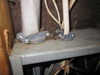
Good news is I passed inspection, everything works, and I'm happy with it. Fishing the 2/0 through the conduit did prove to be a pain. For the most part it went fairly easy, especially in 2.5" conduit and using cable lube. There was one snag towards the end of the run, after about 225 deg of bends where I had one of the bell ends turned the wrong way. The end of the wire kept hanging up on that lip of plastic in the SCH 80 and I didn't have much torque to get it to go, with so much fed out and so many bends. I ended up getting a cable sock/grip and kept some tension on it through the other end with a nylon line, while pushing from the LB. Had to wrap the end of the THHN in electrican's tape first - the outer layer of nylon on the wire is too slippery for the cable sock to grab it without that.

Another tip, for anyone who might be fishing electrical lines, low voltage cable, or anything though conduit for that matter. After I had assembled and cemented all of the conduit, I was able to run the electrician's nylon/poly line through by tying the end of it to a medium chunk of sytrofoam and then blowing it through the conduit with compressed air. Easiest and fastest part of the whole project.

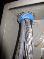
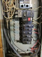
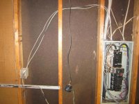
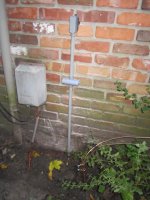
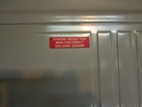
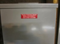
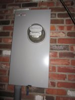
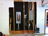
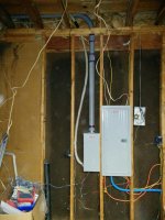
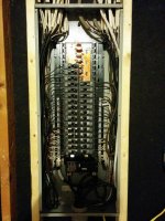
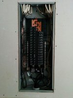
On the big day, the POCO pulled the meter for me, I landed everything from the new feeder in the 200 amp disconnect in the shop, and then made the connections in the new subpanel. Then the fun part was feeding all of the NM branch circuit cables back through the top plate in the attic and making up all of my connections in the sub. I still have aluminum branch circuits (will be next on to do list), but at least they are all on the correct breakers based upon their rating now - 12 ga Al on 15 amp breakers, not 20's. I also added my new GFCI next to the subpanel, and I have a handful of extra spaces for future use. Inspector came by, gave me a thumbs up, and had the POCO replace the meter and seal up the can. RTG - ready to go!
 

Attachments

  • IMG_20150624_200649.jpg
    IMG_20150624_200649.jpg
    136.5 KB · Views: 30
  • IMG_20150625_001950.jpg
    IMG_20150625_001950.jpg
    144.7 KB · Views: 37
  • IMG_20150625_225235.jpg
    IMG_20150625_225235.jpg
    145.9 KB · Views: 42
  • IMG_20150703_172615.jpg
    IMG_20150703_172615.jpg
    137.3 KB · Views: 39
  • IMG_20150703_173107.jpg
    IMG_20150703_173107.jpg
    136.5 KB · Views: 33
  • IMG_20150703_173140.jpg
    IMG_20150703_173140.jpg
    145.4 KB · Views: 32
  • 032886911248.jpg
    032886911248.jpg
    57.2 KB · Views: 26
To avoid these ads, REGISTER NOW!
Top Bottom