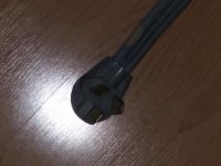
You're getting a bit ahead of yourself - first things first. Your plug wiring is fine - like I said before, it doesn't matter which wire goes to which of the two hot blades.
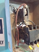
Yes, the arcing on the terminals is from interrupting 50+ amps when you are disconnecting the plug under load (motor will draw at least 50 amps at locked rotor meaning it is not turning). That is normal, but the plug isn't designed for this type of use. Ideally, you would have a 30A (or larger) disconnect switch there to use for your purposes. But plug will work for now - just try to pull it free as quickly as possible to minimize the arcing.
I don't see a link to your original thread with the pictures showing the pump, but let's go with that it has a centrifugal unloader. Then you only need to add a small switch in series with the pressure switch. For now, don't worry about that.
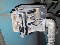
First find out where the buzzing/humming is coming from - motor, contactor, or both.
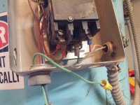
Next I would test for 240VAC (or in that range - it may be as low as 220VAC) across the top two terminals on the starter that are connected to the motor - the upper left one at the overload heater and the lower right one on the contactor. If you have voltage there, then you go to the junction box on the motor and check for voltage there (or just do a continuity check from starter to there on the red & blue wires).
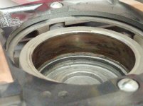
If you have voltage at the motor, then it is time to check motor capacitors and the centrifugal starting switch inside one end of it (you'll have to remove one end of the motor to get to it). If all of that checks out OK, then worst-case scenario is that you have a shorted run or start winding (which is not economically repairable). Plenty of info on the web for how to do all of this including youtube videos. For starters, do a resistance check between the motor leads and ground - there should be an open circuit here).
Good luck and keep us posted. And be safe. You may want to connect the ground wires for your own protection.
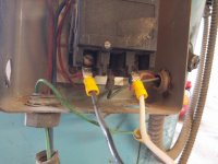
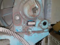
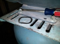
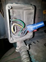
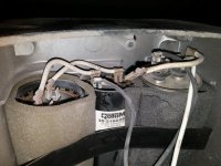
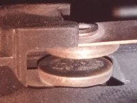
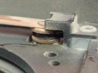
Alright, good news, I didn't start any fires, no one got electrocuted. I have attached pictures of the motor junction box and the motor with the end cap removed, I don't have a clue what I am looking at there. Also a pic of the spring washer that fell out.
On to the test results.
1. double checked the outlet, 240v.
2. double checked the extension cord, 240v
3. flipped the breaker, a very loud hum / buzz, definitely coming from the motor, honestly it was too loud to tell if it was coming from the starter.
After a short period of time loud click, plastic switch on overload popped out and the buzzing stopped.
4. checked between T2 on the overload and T1 on the contactor, I had about 226 volts until the overload tripped.
5. checked continuity, there was continuity between all 3 wires in the starter and all 3 wires in the motor junction box.
Thats about as far as I got. I did quickly google the centrifugal switch, which I didn't realize there was one in the motor, I thought you were talking about the compressor, but that was about as far as I got.
Other things I noted, the motor was very hot to the touch, probably 30 to 45 minutes after I last started it, still hot now but going to bed.
I know how to test the capacitors but I am lost about the centrifugal switch.