OP

You are using an out of date browser. It may not display this or other websites correctly.
You should upgrade or use an alternative browser.
You should upgrade or use an alternative browser.
Logan 922 ca.1951 Restoration
- Thread starter OldeTimeEtc
- Start date

OP
OldeTimeEtc
Well-known member
June 13, 2015
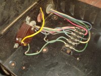
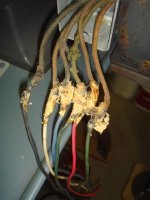
So after I cut myself 6 lengths of wire leaving enough extra to work with for whatever reasons ...like routing, mistakes, etc.....(after all its better to have them too long then too short)......I ran the wires as a group into the new conduit before I attached the other end to the central electrical box. This made it a lot smoother than trying to snake them thru a small bend and the metal tube at the other of the connected conduit. I also ran a 7th wire (green ground) from the central box to the motor wire housing for an added ground.
So after I cut myself 6 lengths of wire leaving enough extra to work with for whatever reasons ...like routing, mistakes, etc.....(after all its better to have them too long then too short)......I ran the wires as a group into the new conduit before I attached the other end to the central electrical box. This made it a lot smoother than trying to snake them thru a small bend and the metal tube at the other of the connected conduit. I also ran a 7th wire (green ground) from the central box to the motor wire housing for an added ground.
Attachments


OP
OldeTimeEtc
Well-known member
OP
OldeTimeEtc
Well-known member
June 13, 2015
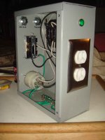
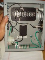
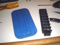
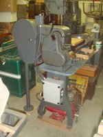
Previously when fabricating the central electrical box I picked up a new 8 gang terminal strip to replace the 6 gang one I had. I also found some scrap ABS plastic sheet I cut into a plate for the strip to mount one for added insulating safety. Once installed I attached all the pertinent wiring with the proper color code to all the recepticles, twist plug and terminal strip. I installed a grounding block to the bottom to handle all the ground wires I needed. I also added a small green power indicator light on the side of the box.......just a preference of mine. I then finally attached the box to the lathe. You'll notice also I added a panel to the rear of the box that shows thru the lathe legs in case I ever want to add something.
Previously when fabricating the central electrical box I picked up a new 8 gang terminal strip to replace the 6 gang one I had. I also found some scrap ABS plastic sheet I cut into a plate for the strip to mount one for added insulating safety. Once installed I attached all the pertinent wiring with the proper color code to all the recepticles, twist plug and terminal strip. I installed a grounding block to the bottom to handle all the ground wires I needed. I also added a small green power indicator light on the side of the box.......just a preference of mine. I then finally attached the box to the lathe. You'll notice also I added a panel to the rear of the box that shows thru the lathe legs in case I ever want to add something.
Attachments

OP
OldeTimeEtc
Well-known member
June 13, 2015
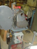
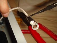
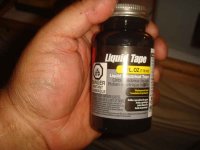
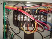
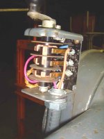
Last detail was routing all the wiring to the proper connector on the terminal block. While routing wire I always leave a little extra length of wire just in case for any reason. Every wire end I crimped on a ring terminal, soldered it and then coated it with some liquid tape. Tape or shrink tube would have worked too....I just found the liquid easier and was just a preference. I also removed the yellow insulator that was on each terminal ring because they just got in my way especially while soldering. Another reason I insulated the ends with liquid tape. Last also was replacing and routing new wiring for the switch and because of the tight quarters....taking notice of where the wires business ends routed and careful that it didn't touch or ribbed against anything internally.....the business ends or the wire itself which can over time wear thru the wire insulating and cause problems.
Last detail was routing all the wiring to the proper connector on the terminal block. While routing wire I always leave a little extra length of wire just in case for any reason. Every wire end I crimped on a ring terminal, soldered it and then coated it with some liquid tape. Tape or shrink tube would have worked too....I just found the liquid easier and was just a preference. I also removed the yellow insulator that was on each terminal ring because they just got in my way especially while soldering. Another reason I insulated the ends with liquid tape. Last also was replacing and routing new wiring for the switch and because of the tight quarters....taking notice of where the wires business ends routed and careful that it didn't touch or ribbed against anything internally.....the business ends or the wire itself which can over time wear thru the wire insulating and cause problems.
Attachments
OP
OldeTimeEtc
Well-known member
OP
OldeTimeEtc
Well-known member
OP
OldeTimeEtc
Well-known member
OP
OldeTimeEtc
Well-known member
June 15, 2015
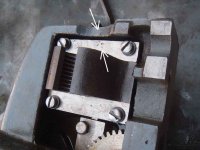
I also removed the half nut but before I did I noticed that it could be reinstalled facing both ways and since I feel its very important to reinstall old parts the same exact way they came apart I always mark them in such a way to help me remember which way they were facing to assure they go back together the same way. My opinion is that old parts once having "broken in" should be returned (reinstalled) the same way to assure smoother operation since they are already settled in. I usually punch a tiny mark in a non-harmful area to show me which way they were originally installed as you can see in the pic.
I also removed the half nut but before I did I noticed that it could be reinstalled facing both ways and since I feel its very important to reinstall old parts the same exact way they came apart I always mark them in such a way to help me remember which way they were facing to assure they go back together the same way. My opinion is that old parts once having "broken in" should be returned (reinstalled) the same way to assure smoother operation since they are already settled in. I usually punch a tiny mark in a non-harmful area to show me which way they were originally installed as you can see in the pic.
Attachments
OP
OldeTimeEtc
Well-known member
June 15, 2015
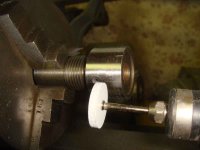
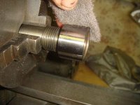
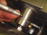
Once cleaned up I turned my attention to remove rust and brightening up the exposed parts of the knobs, wheels and machined ways. One graduate indicator had several deep marks and scratches I had to spin it in my other lathe and used my Dremel tool with a fine finish disc to remove them and then put on a nice satin brushed finish. I also took a hard tipped scratch awl marker and sharpened the indicator line.
Once cleaned up I turned my attention to remove rust and brightening up the exposed parts of the knobs, wheels and machined ways. One graduate indicator had several deep marks and scratches I had to spin it in my other lathe and used my Dremel tool with a fine finish disc to remove them and then put on a nice satin brushed finish. I also took a hard tipped scratch awl marker and sharpened the indicator line.
Attachments
OP
OldeTimeEtc
Well-known member
June 15, 2015
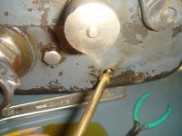
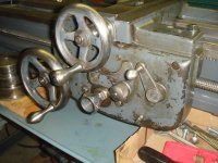
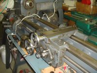
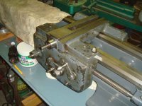
After reassembling the carriage I gave it an initial oiling then installed it on the the lathe bed unfinished since it was a might lighter to handle. I then replaced all the wheels then finished oiling and made all the adjustments. Last I filled the apron with the proper amount of oil.
After reassembling the carriage I gave it an initial oiling then installed it on the the lathe bed unfinished since it was a might lighter to handle. I then replaced all the wheels then finished oiling and made all the adjustments. Last I filled the apron with the proper amount of oil.
Attachments
OP
OldeTimeEtc
Well-known member
OP
OldeTimeEtc
Well-known member
OP
OldeTimeEtc
Well-known member
OP
OldeTimeEtc
Well-known member
OP
OldeTimeEtc
Well-known member
OP
OldeTimeEtc
Well-known member
OP
OldeTimeEtc
Well-known member
OP
OldeTimeEtc
Well-known member
OP
OldeTimeEtc
Well-known member
OP
OldeTimeEtc
Well-known member
June 17, 2015
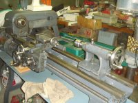
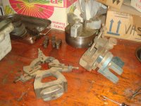
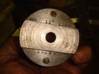
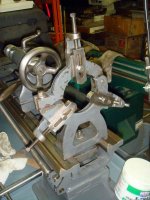
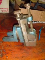
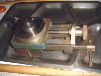
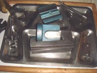
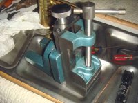
All I have left to do is a couple parts I need either replaced or repaired which will be done as money is available. For now I'll work on some of the tooling that I got with the lathe.......the chuck, steady rest, a milling attachment made by Palmgren and ........
All I have left to do is a couple parts I need either replaced or repaired which will be done as money is available. For now I'll work on some of the tooling that I got with the lathe.......the chuck, steady rest, a milling attachment made by Palmgren and ........
Attachments
OP
OldeTimeEtc
Well-known member

OP
OldeTimeEtc
Well-known member
OP
OldeTimeEtc
Well-known member
OP
OldeTimeEtc
Well-known member
OP
OldeTimeEtc
Well-known member
OP
OldeTimeEtc
Well-known member
OP
OldeTimeEtc
Well-known member
June 20, 2015
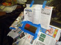
For now project is at a stand still till I can get a couple parts repaired or replaced to complete the lathe but Something dawned on me today...forgot to take care of a minor detail. I had cleaned the Lathe's badge but being brass it will eventually tarnish and darken so to keep it bright I put a couple coats of clear satin on it. Didn't take long to mask off and take care of that little detail....
For now project is at a stand still till I can get a couple parts repaired or replaced to complete the lathe but Something dawned on me today...forgot to take care of a minor detail. I had cleaned the Lathe's badge but being brass it will eventually tarnish and darken so to keep it bright I put a couple coats of clear satin on it. Didn't take long to mask off and take care of that little detail....
Attachments


Last edited:
OP
OldeTimeEtc
Well-known member
June 21, 2015
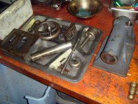
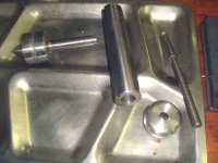
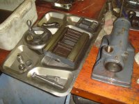
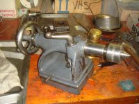
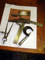
Since things are at a temporary stand still. today I also decided to do a little project I've had on my mind for awhile.......originally I was going to purchase the part from Logan but the more I thought about it cost-wise the more I just didn't want to pay it considering the part was so easy to make myself and the price I thought was a bit much considering its $35 price tag plus shipping. So today I decided to go ahead and make the" Dauber" that's been missing on the tail stock. So looking on the internet I found a very good picture of it with a rule next to it to give me scale.....perfect! So I found a piece of scrape steel rod and got a few tools together and plotted the dimensions based off the photograph I found using the ruler to get the measurements.
Since things are at a temporary stand still. today I also decided to do a little project I've had on my mind for awhile.......originally I was going to purchase the part from Logan but the more I thought about it cost-wise the more I just didn't want to pay it considering the part was so easy to make myself and the price I thought was a bit much considering its $35 price tag plus shipping. So today I decided to go ahead and make the" Dauber" that's been missing on the tail stock. So looking on the internet I found a very good picture of it with a rule next to it to give me scale.....perfect! So I found a piece of scrape steel rod and got a few tools together and plotted the dimensions based off the photograph I found using the ruler to get the measurements.
Attachments
OP
OldeTimeEtc
Well-known member
June 21, 2015
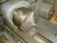
Since this isn't a part that needs real precise dimensions things didn't have to be measured to the nearest 1000th of an inch. The only measurement I honestly needed to worry about was just the diameter of the main body that sits in the hole on the tailstock which was just a tad over 5/16". Once I had that rod sanded down to a nice test fit the rest came easy without a hitch. But first I needed to cut the daubing end to 1/8" x aprox 17/32 then mark off the main body and ball top. I then severed it off with a cut off bit.
Since this isn't a part that needs real precise dimensions things didn't have to be measured to the nearest 1000th of an inch. The only measurement I honestly needed to worry about was just the diameter of the main body that sits in the hole on the tailstock which was just a tad over 5/16". Once I had that rod sanded down to a nice test fit the rest came easy without a hitch. But first I needed to cut the daubing end to 1/8" x aprox 17/32 then mark off the main body and ball top. I then severed it off with a cut off bit.
Attachments

OP
OldeTimeEtc
Well-known member
June 21, 2015
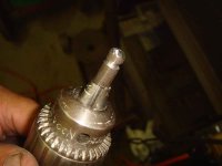
Being lazy and not finding the need to make a cutting bit to cut a ball end I first rough cut it mounted in my power hand drill and used a filed to rough the shape out. I then put it back on my lathe and sanded the main body till it test fit just right in its mounting hole on the Logan tailstock.
Being lazy and not finding the need to make a cutting bit to cut a ball end I first rough cut it mounted in my power hand drill and used a filed to rough the shape out. I then put it back on my lathe and sanded the main body till it test fit just right in its mounting hole on the Logan tailstock.
Attachments
OP
OldeTimeEtc
Well-known member

OP
OldeTimeEtc
Well-known member
June 21, 2015
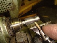
Finally onto my Boley lathe to do all the finish work. Everything was done "freehand" just like using a wood lathe. I cut a nice round ball then sanded and polished it. Turned it around then rough filed the dauber tip to a slight taper and then sanded and polished it to a nice brushed satin finish.
Finally onto my Boley lathe to do all the finish work. Everything was done "freehand" just like using a wood lathe. I cut a nice round ball then sanded and polished it. Turned it around then rough filed the dauber tip to a slight taper and then sanded and polished it to a nice brushed satin finish.
Attachments



OP
OldeTimeEtc
Well-known member


OP
OldeTimeEtc
Well-known member
July 7, 2015
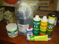
Have been waiting for certain parts to be repaired before I can complete the lathe and the guy is taking longer then expected. Today at least I finally received all the lubricants I ordered for the lathe plus other uses I have for them. Couldn't get what I wanted locally so had to order everything. These are my own personal choices based on my reading and research...their uses I choose are as follows:
Mobile Vactra #2 ...Way Oil and general lubrication of the lathe
Lucas Xtra-Heavy Duty Grease .... Gear Lube
3 in One Motor Oil ..... General Electric Motor Lube for bushings
CMD Extreme Pressure Lube #3 .... Lube for dead centers, followers and steady rests
A-9 Aluminum Cutting Fluid .... Pretty much speaks for itself
Rapid Tap Cutting Fluid .... speaks for itself too
Super K05 Chuck Grease .... Lathe Chuck Lube (going to give this a try as an experiment despite all the pros and cons)
Have been waiting for certain parts to be repaired before I can complete the lathe and the guy is taking longer then expected. Today at least I finally received all the lubricants I ordered for the lathe plus other uses I have for them. Couldn't get what I wanted locally so had to order everything. These are my own personal choices based on my reading and research...their uses I choose are as follows:
Mobile Vactra #2 ...Way Oil and general lubrication of the lathe
Lucas Xtra-Heavy Duty Grease .... Gear Lube
3 in One Motor Oil ..... General Electric Motor Lube for bushings
CMD Extreme Pressure Lube #3 .... Lube for dead centers, followers and steady rests
A-9 Aluminum Cutting Fluid .... Pretty much speaks for itself
Rapid Tap Cutting Fluid .... speaks for itself too
Super K05 Chuck Grease .... Lathe Chuck Lube (going to give this a try as an experiment despite all the pros and cons)
Attachments
Last edited:
OP
OldeTimeEtc
Well-known member
More to come once I receive the last of the parts I need....stay tuned...
raddksn
Well-known member

OP
OldeTimeEtc
Well-known member
Nice work! I'm restoring a Montgomery wards 10x24 Logan with a QC added on. I sent Scott Logan the ser# and he replied it was made for wards in 1942.
Nice lathe....I hope you'll post pics when its done.
Steinmetz
Well-known member
Nice work! I'm restoring a Montgomery wards 10x24 Logan with a QC added on. I sent Scott Logan the ser# and he replied it was made for wards in 1942.
The Wards lathes are generally stamped with a "W" next to the serial number at the end of the bed.
Steinmetz
Well-known member
More to come once I receive the last of the parts I need....stay tuned...
You need to make some leveling jacks for the legs. The thing will never cut to your satisfaction unless it is properly leveled.
The Logan lathes are an excellent small lathe. Better IMO than the South Bend because the Logan has high quality anti-friction bearings in the headstock. They are very similar to operate, though.