To avoid these ads, REGISTER NOW!

Logan 922 ca.1951 Restoration

OP
O

OldeTimeEtc

Well-known member
Joined
Aug 16, 2014
Messages
478
Location
Palm springs area in S. Calif
May 24, 2015
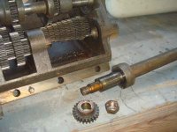
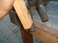
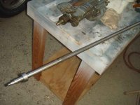
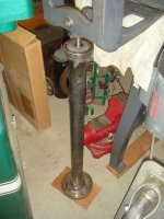
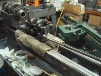
So first order of business was to remove the lead screw. Using a channel lock to hold the shaft and a towel to protect it, I removed the nut holding it to the gear box. Then with a few taps using a piece of wood to protect the shaft I tapped it loose and removed it.
 

Attachments

  • DSC01850.jpg
    DSC01850.jpg
    81 KB · Views: 21
  • DSC01852.jpg
    DSC01852.jpg
    76.6 KB · Views: 21
To avoid these ads, REGISTER NOW!
OP
O

OldeTimeEtc

Well-known member
Joined
Aug 16, 2014
Messages
478
Location
Palm springs area in S. Calif
May 24, 2015
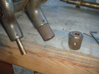
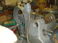
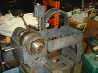
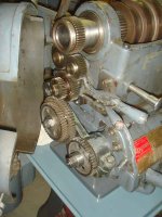
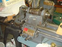
Next I loosened the set screws holding the knobs on the gear box levers and tapped them loose with a hammer and piece of wood. If you'll notice in the next pic I slipped while removing the lead screw and my thump suffered for it.
 

Attachments

  • DSC01853.jpg
    DSC01853.jpg
    61.5 KB · Views: 25
  • DSC01854.jpg
    DSC01854.jpg
    64.5 KB · Views: 24
  • DSC01855.jpg
    DSC01855.jpg
    68.2 KB · Views: 23
OP
O

OldeTimeEtc

Well-known member
Joined
Aug 16, 2014
Messages
478
Location
Palm springs area in S. Calif
May 24, 2015
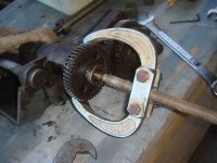
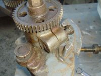
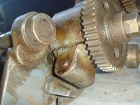
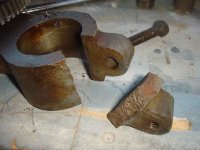
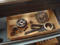
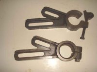
Another set back......I found the gear change bracket had cracked and was broken. I'll make a trip to the a local machinist I know whose good at welding cast iron. I hope he can fix this. This of course means me having to disassemble parts I hadn't planned on. So off to my tool box to get my gear puller....
 

Attachments

  • DSC01859.jpg
    DSC01859.jpg
    72.5 KB · Views: 28
  • DSC01858.jpg
    DSC01858.jpg
    87.8 KB · Views: 25
  • DSC01857.jpg
    DSC01857.jpg
    79.6 KB · Views: 25
  • DSC01856.jpg
    DSC01856.jpg
    88.9 KB · Views: 28
OP
O

OldeTimeEtc

Well-known member
Joined
Aug 16, 2014
Messages
478
Location
Palm springs area in S. Calif
May 24, 2015
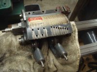
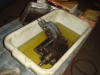
So after a good soak and lots of scrubbing then drying completely with compressed air I cleaned up the gear box and other parts. Now before I can reassemble this on the lathe I'll have to go order some good "open gear grease" but while I'm waiting for my order I put a few drops of oil on all the gear pivots and moving parts of the gear box to keep them lubed.....
 

Attachments

  • DSC01872.jpg
    DSC01872.jpg
    75.8 KB · Views: 28
  • DSC01870.jpg
    DSC01870.jpg
    67.6 KB · Views: 29
  • DSC01869.jpg
    DSC01869.jpg
    76.8 KB · Views: 37
  • DSC01867.jpg
    DSC01867.jpg
    67.7 KB · Views: 28
OP
O

OldeTimeEtc

Well-known member
Joined
Aug 16, 2014
Messages
478
Location
Palm springs area in S. Calif
May 25, 2015
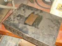
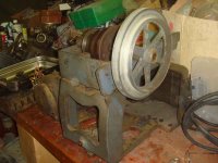
The quick change gear box while all done I temporarily put aside for now. First I wanted to study the motor drive assembly and just how to take it apart minimally for cleaning and then which parts to install it to my lathe first then build from that.
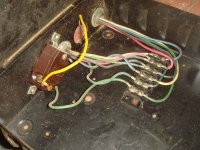
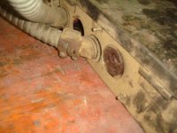
After that was mapped out in my head I then decided to study the motor wiring to figure out just what the last owner had in mind powering it. After looking it over it finally donned on me just what and why he did it this way with the extra large electrical box....(repurposing it and just happen to had it handy most likely)
 

Attachments

  • DSC01873.jpg
    DSC01873.jpg
    83.2 KB · Views: 27
OP
O

OldeTimeEtc

Well-known member
Joined
Aug 16, 2014
Messages
478
Location
Palm springs area in S. Calif
May 25, 2015
The day we moved this out of the garage I only switched it on quickly just to see if it would run never taking the time to study this part of the machine. Now while studying it I finally know how I'm going to power the lathe all the while using part of what he did and improving on it......but that part will be discussed later once I have the design drawn up in my head and what I'll need to fabricate what I have in mind. The electrical box I'll not reuse for the lathe but it is interesting where I think it came from.
 

Attachments

  • DSC01879.jpg
    DSC01879.jpg
    80.5 KB · Views: 22
OP
O

OldeTimeEtc

Well-known member
Joined
Aug 16, 2014
Messages
478
Location
Palm springs area in S. Calif
Upon reading the plaque on the box I believe this once was installed on a ship or plane. Perhaps others on this forum may have their own ideas.
 

Attachments

  • DSC01878.jpg
    DSC01878.jpg
    100.6 KB · Views: 55
OP
O

OldeTimeEtc

Well-known member
Joined
Aug 16, 2014
Messages
478
Location
Palm springs area in S. Calif
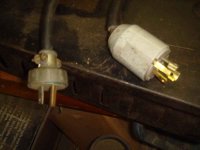
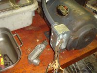
Studying the way he married all the wiring was at least correctly done. The motor powers on and forward and reverse works fine but............
 

Attachments

  • DSC01874.jpg
    DSC01874.jpg
    97.6 KB · Views: 30
OP
O

OldeTimeEtc

Well-known member
Joined
Aug 16, 2014
Messages
478
Location
Palm springs area in S. Calif
Anyway this set up at least gave me a great idea of how I wanted to wire and power the lathe and will be shown later once I decide how to fabricate or find just what I want......stay tuned....
 
OP
O

OldeTimeEtc

Well-known member
Joined
Aug 16, 2014
Messages
478
Location
Palm springs area in S. Calif
May 27, 2015
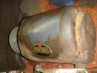
Thought today I'd get busy tearing down the motor mount and drive for cleaning...First removed the switch and motor with all electrical...
 

Attachments

  • DSC01882.jpg
    DSC01882.jpg
    71.6 KB · Views: 25
OP
O

OldeTimeEtc

Well-known member
Joined
Aug 16, 2014
Messages
478
Location
Palm springs area in S. Calif
May 27, 2015
I then removed almost all basic parts, bolts, nuts, pins and shafts for cleaning up...all were rusty and needed "shining" up.
 

Attachments

  • DSC01883.jpg
    DSC01883.jpg
    73.6 KB · Views: 19
  • DSC01886.jpg
    DSC01886.jpg
    57.9 KB · Views: 19
OP
O

OldeTimeEtc

Well-known member
Joined
Aug 16, 2014
Messages
478
Location
Palm springs area in S. Calif
May 28, 2015
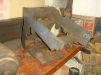
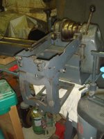
Today it was load up the drive box assembly and motor mount and off to the car wash. Before loading it up I sprayed degreaser all over the skeletal assembly and let it sit first. Nothing beats a coin car wash when you need a high pressure washer and can't afford one. So I blasted all the **** off the assembly, washed my car off and ran back home. At home I blew off the wet assembly until dry then wiped it with clean diesel fuel to make sure It was completely cleaned. then reassembled all the cleaned nuts, bolts and misc parts I had brightened up earlier. Then it was reinstalled back on the lathe.
 

Attachments

  • DSC01893.jpg
    DSC01893.jpg
    75.6 KB · Views: 29
  • DSC01894.jpg
    DSC01894.jpg
    77.1 KB · Views: 31
Last edited:
OP
O

OldeTimeEtc

Well-known member
Joined
Aug 16, 2014
Messages
478
Location
Palm springs area in S. Calif
May 29, 2015
On Friday I went down to see my good friend Randy who now had time to help me (after work) finish the Pedestal.....I have to admit hes a much better welder than I am plus he has a mig welder and I only have arc. So we got busy finishing assembling the pedestal with all the parts I had made.
 

Attachments

  • DSC01898.jpg
    DSC01898.jpg
    81.9 KB · Views: 34
  • DSC01900.jpg
    DSC01900.jpg
    97.1 KB · Views: 34
  • DSC01901.jpg
    DSC01901.jpg
    82.9 KB · Views: 37
To avoid these ads, REGISTER NOW!
OP
O

OldeTimeEtc

Well-known member
Joined
Aug 16, 2014
Messages
478
Location
Palm springs area in S. Calif
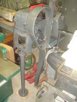
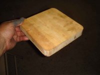
Although the pedestal dimensions are exactly that of a factory one (29" high)...I had to make a foot out of wood to raise it to the same level as the lathe because I had to raise the lathe in order to level it.
 

Attachments

  • DSC01910.jpg
    DSC01910.jpg
    46.9 KB · Views: 8
OP
O

OldeTimeEtc

Well-known member
Joined
Aug 16, 2014
Messages
478
Location
Palm springs area in S. Calif
May 31, 2015
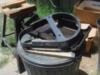
Also pounded out the folds and dents in the guard cover for the main drive pulleys...then primed and painted it.
 

Attachments

  • DSC01904.jpg
    DSC01904.jpg
    66.2 KB · Views: 21
  • DSC01905.jpg
    DSC01905.jpg
    72.5 KB · Views: 23
OP
O

OldeTimeEtc

Well-known member
Joined
Aug 16, 2014
Messages
478
Location
Palm springs area in S. Calif
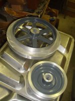
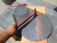
Cleaned up the Drive pulleys, primed and painted them.....I will put the finishing touches on these pulleys after they are installed and running on the machine. .....
 

Attachments

  • DSC01909.jpg
    DSC01909.jpg
    59.7 KB · Views: 16
OP
O

OldeTimeEtc

Well-known member
Joined
Aug 16, 2014
Messages
478
Location
Palm springs area in S. Calif
After much searching I found and finally got my new part in the mail so I will finish assembling the quick change gear box and lead screw. I'll keep the broken part and eventually have it welded to keep as a spare.
 

Attachments

  • DSC01915.jpg
    DSC01915.jpg
    54.4 KB · Views: 22
OP
O

OldeTimeEtc

Well-known member
Joined
Aug 16, 2014
Messages
478
Location
Palm springs area in S. Calif
June 2, 2015
Well now that I have the banjo bracket I needed I got started installing the rest of the gears, quick change gear box and lead screw. I have mulled over for a long time just what kind of grease I should use for the gears. I have researched several forums and talked to others on the subject. Even discussed this with Steve Logan of the Logan Actuator Company. I have looked at dozens of greases and although "Open Gear Grease" seems to be ideal I just had no desire to use the type I could only find locally which all I could find is I believe graphite bashed and its a black nasty grease that gets all over everything and stains black anything it touches and basically makes a huge mess. So finally after searching several local sources I decided on this grease....
 

Attachments

  • DSC01919.jpg
    DSC01919.jpg
    65.6 KB · Views: 35
OP
O

OldeTimeEtc

Well-known member
Joined
Aug 16, 2014
Messages
478
Location
Palm springs area in S. Calif
June 2, 2015
Now keep in mind this s a personal choice and not a recommendation. I just found this grease ideal for my needs...many I've talked to have other choices of what they use.......well this was what I chose. Again, it's just MY personal choice...so far I like it. One thing I liked about this grease besides being "clean" is also the label on the jar read that it resists being slung at high speeds.
So I got to putting grease on sparingly on all the Quick Change Gearbox gears and on the gears on the side of the lathe. Rotated them then wiped off the excess and so far it feels good. I'll know for sure once the lathe is running if I had made the right choice.
 

Attachments

  • DSC01917.jpg
    DSC01917.jpg
    85.2 KB · Views: 23
OP
O

OldeTimeEtc

Well-known member
Joined
Aug 16, 2014
Messages
478
Location
Palm springs area in S. Calif
June 2, 2015
I then finished installing the banjo bracket, gear box and lead screw.......
 

Attachments

  • DSC01920.jpg
    DSC01920.jpg
    86.8 KB · Views: 25
  • DSC01922.jpg
    DSC01922.jpg
    85.2 KB · Views: 29
  • DSC01923.jpg
    DSC01923.jpg
    82.9 KB · Views: 22
OP
O

OldeTimeEtc

Well-known member
Joined
Aug 16, 2014
Messages
478
Location
Palm springs area in S. Calif
June 2, 2015
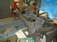
I finished up the night assembling the rest of the misc parts to just about complete the headstock...the pedestal, drive box cover and drive pulley guard frame, plus finished the drive.pulley details..........
 

Attachments

  • DSC01935.jpg
    DSC01935.jpg
    77.6 KB · Views: 24
  • DSC01936.jpg
    DSC01936.jpg
    74.4 KB · Views: 22
  • DSC01924.jpg
    DSC01924.jpg
    79 KB · Views: 24
OP
O

OldeTimeEtc

Well-known member
Joined
Aug 16, 2014
Messages
478
Location
Palm springs area in S. Calif
June 3, 2015
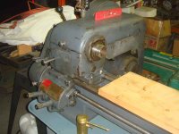
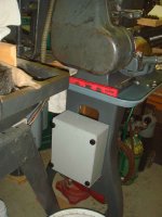
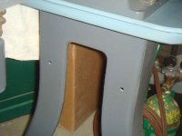
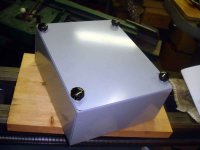
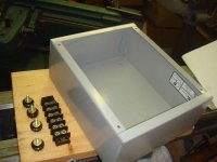
....I also laid the motor on its mount as a temporary "mock-up" so I could write my grocery list of electrical parts I will need. First off I found a nice metal electrical enclosure that perfectly fit the bill......I retapped the holes for the cover and found some nice knobs to replace the screws for easier tool-less access to the box. When assembling the legs I made sure the pair of legs with the small drilled holes were on the headstock side of the lathe so I could make use of them rather than having to drill additional holes in the legs. I then mounted the box. This is where all electrical will converge for the lathe. Looks sharp so far...least I think so.....
 

Attachments

  • DSC01929.jpg
    DSC01929.jpg
    70.5 KB · Views: 17
  • DSC01928.jpg
    DSC01928.jpg
    54.5 KB · Views: 14
  • DSC01925.jpg
    DSC01925.jpg
    56.1 KB · Views: 15
  • DSC01927.jpg
    DSC01927.jpg
    60.3 KB · Views: 17
  • DSC01926.jpg
    DSC01926.jpg
    57.9 KB · Views: 16
OP
O

OldeTimeEtc

Well-known member
Joined
Aug 16, 2014
Messages
478
Location
Palm springs area in S. Calif
June 6, 2015
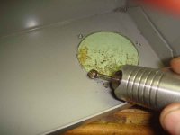
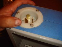
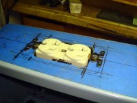
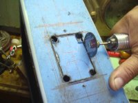
Today I got busy mapping out and cutting the holes in the electrical box for the conduit connectors, receptacles and twist lock inlet plug for the power supply. First took a metal hole saw, cut the hole for the twist plug and cleared off the sharp flashing with my foredom, drilled and tapped the screw holes and then installed the twist plug receptacle. I also drilled the holes for the conduit connectors.
 

Attachments

  • DSC01938.jpg
    DSC01938.jpg
    51.9 KB · Views: 17
  • DSC01937.jpg
    DSC01937.jpg
    62.6 KB · Views: 16
  • DSC01939.jpg
    DSC01939.jpg
    52.8 KB · Views: 16
OP
O

OldeTimeEtc

Well-known member
Joined
Aug 16, 2014
Messages
478
Location
Palm springs area in S. Calif
June 6, 2015
While looking for some metal cutting blades for my jigsaw at the hardware store I came across this new product from Dremel. A set of metal cutting discs with an "EZ Lock" mandrel....Perfect!...just what I needed! The set was on sale too......($5 off retail price of $21)....buying this was way cheaper than buying the discs and mandrel individually. I may even go back and get a second set just to get another mandrel and more discs for later use. These cut the metal box like butter with the extra torque my foredom tool provided. This was a great idea from Dremel...its like having a mini Makita grinder with a cut-off disc. I had all the receptacle plug holes cut out , tapped and installed quick.
 

Attachments

  • DSC01942.jpg
    DSC01942.jpg
    65.9 KB · Views: 16
  • DSC01940.jpg
    DSC01940.jpg
    66.5 KB · Views: 20
  • DSC01941.jpg
    DSC01941.jpg
    62.2 KB · Views: 18
  • DSC01944.jpg
    DSC01944.jpg
    78.8 KB · Views: 20
OP
O

OldeTimeEtc

Well-known member
Joined
Aug 16, 2014
Messages
478
Location
Palm springs area in S. Calif
June 6, 2015
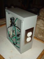
Almost finished fabricating the electrical distribution box for my lathe. As you can see where the side of the box would be facing the back of the lathe are the conduit connectors twist plug and a standard electrical receptacle for onboard convenient power If I need to plug in a lamp or accessory for the lathe rather then go find an extension cord. I added one other receptacle where the side of the box faces toward the front of the lathe. The panel in the back of the box is if I choose to add something else later as an upgrade.
 

Attachments

  • DSC01945.jpg
    DSC01945.jpg
    60.9 KB · Views: 24
  • DSC01946.jpg
    DSC01946.jpg
    62.2 KB · Views: 19
OP
O

OldeTimeEtc

Well-known member
Joined
Aug 16, 2014
Messages
478
Location
Palm springs area in S. Calif
June 7, 2015
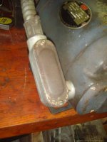
Tonight I decided to get the motor ready for install but first wanted to upgrade the conduit body attached to the side to something with a bit more room and better access to the wiring. Whatever it is I fabricate I always try to keep maintenance in mind. So I removed the conduit body and replaced it with a receptacle box. Now all the wiring isn't sqeezed and stuffed into a tiny space and easier to handle and access if I ever need to work on it.
 

Attachments

  • DSC01930.jpg
    DSC01930.jpg
    65.4 KB · Views: 21
  • DSC01947.jpg
    DSC01947.jpg
    79.9 KB · Views: 21
  • DSC01948.jpg
    DSC01948.jpg
    67.9 KB · Views: 22
OP
O

OldeTimeEtc

Well-known member
Joined
Aug 16, 2014
Messages
478
Location
Palm springs area in S. Calif
June 13, 2015
So first order of business was to "color code" all the wiring and take many photos and keep notes of everything and every connected wire. Since this ran fine when I bought it I can assume it was at least wired right. Having no schematic and not knowing what wire was which coming out of the motor all I had to go by was wiring colors and my knowledge of electricity. Plus the fact that the wiring was so faded I could hardly tell what the old colors were anymore. So off to the hardware store where I picked up a package of many different colored electrical tapes.
 

Attachments

  • DSC01963.jpg
    DSC01963.jpg
    68.4 KB · Views: 9
OP
O

OldeTimeEtc

Well-known member
Joined
Aug 16, 2014
Messages
478
Location
Palm springs area in S. Calif
I then put a colored band on each wire to indicate what colored wire it was attached to. This made it easier where it connected to the old terminal strip I already had pictures of. If I didn't have a matching color tape I made a tap and labeled it with the proper color name. I also noticed that there was a couple wires with the same colors so I exchanged those with orange and yellow wire and noted it so now I had
 
To avoid these ads, REGISTER NOW!
Top Bottom