To avoid these ads, REGISTER NOW!

Planning for an attached garage subpanel

baneonrt

Well-known member
Joined
Dec 2, 2008
Messages
76
Location
Sacramento, CA
One of these days I'll start a post in the garage gallery about my various projects, but right now I was hoping to get some advice and direction for adding a subpanel to the attached 2-car garage. Mostly concerned with possible permit issues I should plan for now.

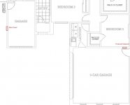
I've attached part of the house layout below. The main panel is made by Square D and is a 200amp service. The required wire run appears to be about 65-70ft through the attic. My main goal is to provide a few 20 amp outlet circuits as well as a new circuit for lighting. The existing garage lighting is on a circuit shared with all three bedrooms including their installed ceiling fans. I'll also install one 240v circuit on the back wall of the garage just in case.


Here is my main panel.


They built in some conduit for expansion and one of my questions is it feasible to utilize this for 6-3 nm-b wire? The conduit extends only to the attic space about 5ft above the panel. If I can't use it I'll have to cut into the sheet rock on the finished/textured garage wall on the other side of the panel.

And here is a closeup of the conduit entrance.


On to the subpanel location. When I bought the place in April of '07 I had custom cabinets installed. This has certainly limited my options on where I can put the subpanel. The location in the picture below is on a firewall but has 34" across and far more than 36" in front of the panel location. The ceiling height is just over 10 feet. The plan would be to cut the drywall and firewall along the studs (currently marked with magnets) almost all the way to the ceiling and then replacing it once the panel was installed and inspection finished.


That brings me to another permit/inspection question. Since the walls are finished can I cut access holes in the drywall so I can install the required wire anchor within 8" of the outlet and every 4 feet or does the inspector need to see the entire cable run? This would be a problem since some runs will need to go behind permanently installed cabinets.

Any help is appreciated.

Steve
 

Attachments

  • fp_forum.jpg
    fp_forum.jpg
    57.6 KB · Views: 94
  • IMG_2069.jpg
    IMG_2069.jpg
    80.5 KB · Views: 115
  • IMG_2066.JPG
    IMG_2066.JPG
    117.8 KB · Views: 84
  • IMG_2051.JPG
    IMG_2051.JPG
    105.8 KB · Views: 43
To avoid these ads, REGISTER NOW!

Mustang51js

Well-known member
Joined
Jan 24, 2014
Messages
1,734
Location
Haskell nj
Are you sure that is a pipe going up, by looking at that picture it looks like a 3/4 plastic romex connector,or one of those plastic corrugated flex pipe connectors. If it's 3/4 pvc then you should have no issues getting down it. If your snaking wires in the wall you don't need to cut Sheetrock open to install straps. Pick up some spray foam fire block since you will need that for the holes coming down to subpanel and if you recess panel they may want it above panel. As far as clearance I think it's 30 inches side to side and 3 ft in front so you should be ok
 
Last edited:
OP
B

baneonrt

Well-known member
Joined
Dec 2, 2008
Messages
76
Location
Sacramento, CA
Thanks for the suggestions. That conduit is some sort of wire pathway. The home builder told me that's what it's for and there is another one at the bottom of the panel I've used to install two 20 amp circuits to the small garage on the other side of the wall. It may be some sort of flex pipe and I'm not sure how much trouble it will be to run the 6-3 through it.

Steve
 
OP
B

baneonrt

Well-known member
Joined
Dec 2, 2008
Messages
76
Location
Sacramento, CA
I'm having a hard time wrapping my mind around load calculations. I was originally planning a 60A subpanel which would house 1 15A breaker for lights, 2 or 3 20A circuits for wall outlets, a 20A 250V outlet for a smaller air compressor and a 30A 250V outlet just in case I end up doing any welding.

Now I'm thinking it might be a good idea for later resale value to make sure that 250V outlet can handle any potential EV car charger. From what I've read Level 2 chargers are around 30-38A draw. Do I need to change anything to support this?


Thanks,

Steve
 

wyliesdiesels

Well-known member
Joined
Aug 14, 2012
Messages
20,279
Location
Modesto, CA
Last edited:

nadogail

Well-known member
Joined
Jan 23, 2009
Messages
32,399
Location
Coronado, CA
A 100 amp sub panel, fed through a 90 amp breaker, will give you a lot of room for growth and a lot of flexibility.

My personal experience is that today's minimum to tomorrow's too little and too late.

You left out of your load calculations your future air compressor, drill press, plasma cutter, etc., etc., and etc.

All shops and garages, in my experience, are "works in progress".
 

pattenp

Well-known member
Joined
Jun 4, 2008
Messages
10,175
Location
Virginia - USA
I do believe 6-3 NM-b is too large for 3/4" PVC conduit. It will exceed fill limits. I'm looking at Southwire dia for 6-3 NM-b as being 650 mil. Dia of 650 mil is .331 sq. in. The fill limit on 3/4" PVC is 40% or .203 sq.in. with more than 2 conductors.

Edit: I wasn't thinking about the OP's 3/4" conduit is just a sleeve, so I guess the 6-3 NM-b should be fine. Just what are the fill requirements for sleeves over 2ft.?
 
Last edited:
OP
B

baneonrt

Well-known member
Joined
Dec 2, 2008
Messages
76
Location
Sacramento, CA
I do believe 6-3 NM-b is too large for 3/4" PVC conduit. It will exceed fill limits. I'm looking at Southwire dia for 6-3 NM-b as being 650 mil. Dia of 650 mil is .331 sq. in. The fill limit on 3/4" PVC is 40% or .203 sq.in. with more than 2 conductors.

Edit: I wasn't thinking about the OP's 3/4" conduit is just a sleeve, so I guess the 6-3 NM-b should be fine. Just what are the fill requirements for sleeves over 2ft.?

I like the idea of using less expensive aluminum wire with more capacity as wylie mentioned. And I agree with the idea of overbuilding it as long as it doesn't add a large amount of complication to the project. It would certainly eliminate that 3/4" "sleeve" or whatever it is from the equation altogether. Are there any drawbacks that haven't been mentioned?

Maybe a simple question but since the main panel is installed on the outside of a finished wall can I just fish the #2 AL SER through the wall into a knockout on the main panel or do I need to open up the wall to properly secure it?

Steve
 
To avoid these ads, REGISTER NOW!
OP
B

baneonrt

Well-known member
Joined
Dec 2, 2008
Messages
76
Location
Sacramento, CA
Thanks for the advice so far. This past weekend a overcame a stumbling block in this project. The attic area above my main panel was sealed off by the roofing panels left in place between the different roof lines on the house. I managed to create an access hole and am now ready to finalize my plans and get to implementation. Here is what I'm planning, anything look off?

#2 AL SER for ~65-70' run from 200A main panel to subpanel through attic.

90A breaker for main panel.

Square D (to match the main panel) subpanel from Home Depot. This one?
http://www.homedepot.com/p/Square-D...h-Cover-Value-Pack-HOM1224L125PGCVP/204836334

One 15A circuit in the main panel currently is dedicated to an outlet in the garage that was originally for the sprinkler system. This wire runs right past where I need to put a new ceiling mounted outlet for my Liftmaster 8500 opener. Was going to repurpose this circuit for the opener as well as put one bank of my ceiling mounted light fixtures on this circuit to isolate them from the rest of the garage lighting which will be ran in the subpanel.

West wall has my workbench with 4 20A outlets on one breaker. Will wire these into the new subpanel.

North wall add 20A 110/220V combo outlet for medium sized air compressor. Assuming I'll have to use an expensive GFCI 220V 20A breaker for this since it's in a garage and one side of the outlet is 110v? Outlet: http://www.amazon.com/dp/B000U3BVMI/?tag=atomicindus08-20. I don't have the compressor yet so just wanted flexibility at this location.

Also on north wall adding one dedicated 20A circuit for general use and an additional 20A circuit for the sprinkler system.

East wall installing one 20A outlet and one 50A 220V outlet.

One 15A circuit for the rest of my ceiling lighting which consists of 5 or 6 4 bulb fixtures.

Anything look amiss? I'm planning on going to the building department this week to apply for the permit.

Steve
 
OP
B

baneonrt

Well-known member
Joined
Dec 2, 2008
Messages
76
Location
Sacramento, CA
So I took my camera up with me this time. Picture is above the main panel. Note the other end of the blue corrugated flex pipe or whatever from my first post in this thread.
 

Attachments

  • IMG_2084.jpg
    IMG_2084.jpg
    140.5 KB · Views: 53
Last edited:

brewchief

Well-known member
Joined
Sep 20, 2008
Messages
2,372
Location
Michigan
12 space 24 circuit panel will get full quick, I would go with a 20 space 40 circuit for a few dollars more.

For the compressor circuit I would either run conduit and leave it empty until I had the compressor or run a #10 wire to a box and cap it until I knew exactly what I needed.

While not needed in an attached garage you can use a main breaker panel instead of a main lug panel, it can be nice to kill all power in a panel while working in it.
 
OP
B

baneonrt

Well-known member
Joined
Dec 2, 2008
Messages
76
Location
Sacramento, CA
12 space 24 circuit panel will get full quick, I would go with a 20 space 40 circuit for a few dollars more.

2 spots for the high current 220v circuit
2 more potentially for a lower current 220v air compressor circuit
1 West wall outlets
2 North wall outlets
1 East wall outlets
1 Lighting

Even if I don't use two pole breakers I'm using 9 spots with three to go. That goes down to 7 if I double them up conservatively. This is a 400sqft garage, not much room for expansion or multiple projects going on at one time :)

For the compressor circuit I would either run conduit and leave it empty until I had the compressor or run a #10 wire to a box and cap it until I knew exactly what I needed.

The space I have for a compressor limits me to about 30 gallons max. I've researched different ones and nothing I can find will need more than 20A. Instead of using the combo outlet though I'll just prep it for a 220V circuit but be ready to set it up for either.

While not needed in an attached garage you can use a main breaker panel instead of a main lug panel, it can be nice to kill all power in a panel while working in it.

I agree. I thought the panel I linked was setup that way with the large opening above the two columns of breakers. Am I mistaken?

Also went to the building department today and got the permit so I'm ready to rock and roll.

Steve
 

brewchief

Well-known member
Joined
Sep 20, 2008
Messages
2,372
Location
Michigan

wyliesdiesels

Well-known member
Joined
Aug 14, 2012
Messages
20,279
Location
Modesto, CA
Thanks for the advice so far. This past weekend a overcame a stumbling block in this project. The attic area above my main panel was sealed off by the roofing panels left in place between the different roof lines on the house. I managed to create an access hole and am now ready to finalize my plans and get to implementation. Here is what I'm planning, anything look off?

#2 AL SER for ~65-70' run from 200A main panel to subpanel through attic.

90A breaker for main panel.

Square D (to match the main panel) subpanel from Home Depot. This one?
http://www.homedepot.com/p/Square-D...h-Cover-Value-Pack-HOM1224L125PGCVP/204836334

One 15A circuit in the main panel currently is dedicated to an outlet in the garage that was originally for the sprinkler system. This wire runs right past where I need to put a new ceiling mounted outlet for my Liftmaster 8500 opener. Was going to repurpose this circuit for the opener as well as put one bank of my ceiling mounted light fixtures on this circuit to isolate them from the rest of the garage lighting which will be ran in the subpanel.

West wall has my workbench with 4 20A outlets on one breaker. Will wire these into the new subpanel.

North wall add 20A 110/220V combo outlet for medium sized air compressor. Assuming I'll have to use an expensive GFCI 220V 20A breaker for this since it's in a garage and one side of the outlet is 110v? Outlet: http://www.amazon.com/dp/B000U3BVMI/?tag=atomicindus08-20. I don't have the compressor yet so just wanted flexibility at this location.

Also on north wall adding one dedicated 20A circuit for general use and an additional 20A circuit for the sprinkler system.

East wall installing one 20A outlet and one 50A 220V outlet.

One 15A circuit for the rest of my ceiling lighting which consists of 5 or 6 4 bulb fixtures.

Anything look amiss? I'm planning on going to the building department this week to apply for the permit.

Steve

I wouldnt use that outlet. Its only rated for 2HP max.

Go with a 6-30r that is rated for 3HP and a dedicated 240v circuit which will allow u to not need an expensive 120v/240v GFCI breaker...

So I took my camera up with me this time. Picture is above the main panel. Note the other end of the blue corrugated flex pipe or whatever from my first post in this thread.

The blue pipe is called ENT- electrical non metalic tubing. The slang term is smurf tube...
 
Last edited:
OP
B

baneonrt

Well-known member
Joined
Dec 2, 2008
Messages
76
Location
Sacramento, CA
I wouldnt use that outlet. Its only rated for 2HP max.

Go with a 6-30r rated for 3HP and a dedicated 240v circuit which will allow u to not need an expensive 120v/240v GFCI breaker...

Agreed, I should just install the circuit I need. I need to pick out a compressor still. I currently have a 33 gallon, so loud I only use it when I have to, craftsman.


The blue pipe is called ENT- electrical non metalic tubing. The slang term is smurf tube...

Hehe, that would explain why the builders called it a smurf tube when I asked about adding circuits several years ago after we first moved in :lol:

Steve
 
To avoid these ads, REGISTER NOW!
Top Bottom