To avoid these ads, REGISTER NOW!

Noob to big boy compressors... seeking help

toddjb

Well-known member
Joined
Aug 15, 2013
Messages
81
I came across a screaming deal on an Ingersoll-Rand 80gal T-30 2 stage compressor the other day.

It was disassembled into 3 parts when I got there: pump, motor, tank.

He didn't have 220 so I was unable to test the motor but the motor and pump spun freely so I took the chance.

Got it home, hooked it up to electrical and motor sounds great. Mounted it and the pump. Added oil. It was empty. He said he drained it years before when putting it into storage. And fired it up. Everything sounds really really good. I am very stoked.

Here is how she sit now (Looks to have VERY little use)

IMAG1327_zpsjvezduzs.jpg


Here is where my questions come in.

1) - This is the oil that I put in.

IMAG1325_zpssjrisstn.jpg


There was 16oz. This compressor doesn't have a view window, or a dip stick. It took the whole bottle. Should this be "full", or should I be adding more? Also, is this the right stuff? I'm in an unheated garage in Colorado, so I figured the synthetic would be the best route?

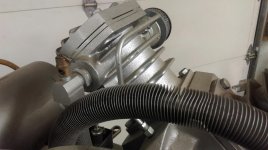
2) - I'm pretty confident I hook the pump into the tank here

37693c44-4a95-4284-9a72-524a2ceda019_zpsfqqwxqad.jpg


A - is this correct? B - is regular black pipe the route to go? C - Thread tape or pipe goop?

3) - The kick on and shut off thingy (that's the technical name) is missing it's lid which I presume had the wiring diagram.

How is this suppose to be hooked up? I presume its suppose to have the Power from the wall running to this first and then from this to the motor, correct? Can anyone shed light on the proper wiring?

IMAG1323_zpsuklaajg6.jpg


IMAG1324_zpsafntz8wo.jpg


Lastly, any other sweet tips and tricks you might be able to share that I might glean from?

Thanks in advance for answering, I'm sure, very basic compressor woes.

Edit: Air Filter - should I just assume it's trash and replace it? If so are they all created equal or is there a dramatic quality difference?
 
To avoid these ads, REGISTER NOW!

Zrexxer

Well-known member
Joined
Jan 23, 2007
Messages
5,058
Location
Pflugerville, TX
Added oil. It was empty. He said he drained it years before when putting it into storage. And fired it up. Everything sounds really really good. I am very stoked

1) - This is the oil that I put in.

There was 16oz. This compressor doesn't have a view window, or a dip stick. It took the whole bottle. Should this be "full", or should I be adding more?

Did you fill it through the hole that has the knob that says "Hand Tighten Only?" Was oil running out of that hole when you were done? If not, it wasn't full.
 
OP
T

toddjb

Well-known member
Joined
Aug 15, 2013
Messages
81
I did fill it through the "Hand Tighten Only" hole. And I did not fill it til oil was running out. So it must take more than one bottle. Thanks Zrexxer.
 

mg283680

Banned
Joined
Jul 23, 2015
Messages
103
Almost running out may work too. :)
Let's have a look at the box with the cable to the right of the motor in the pic above.
 

BK13

Well-known member
Joined
Mar 1, 2013
Messages
2,692
Location
PDX, OR
I'm not going to be any help, but congrats, man. I hope to stumble upon a screaming deal on a big compressor some day. Or a cheap like new Snappy box.
 
OP
T

toddjb

Well-known member
Joined
Aug 15, 2013
Messages
81
mg, the box on the right of the motor holds its capacitors and Motor wires. I'll get a pic later tonight
 

Zrexxer

Well-known member
Joined
Jan 23, 2007
Messages
5,058
Location
Pflugerville, TX
I did fill it through the "Hand Tighten Only" hole. And I did not fill it til oil was running out. So it must take more than one bottle. Thanks Zrexxer.
I suspect that crankcase takes a lot more than 16 oz. So yes, fill it until you can't put anymore in through that hole with the pump sitting in its normal vertical operating position.

As far as the pressure switch, it has the info you need to wire it right there - see where it says LINE-LOAD-LOAD-LINE... the two line terminals are where you connect the two hot legs of the 230V service, and the two load terminals are for the two hot legs going to the motor.

You're probably going to need a mag starter for that machine too, but that's a discussion for on down the road.

Yes, the green line is where your discharge line would be run. You'll need a check valve where it enters the tank, and I can't tell from your photos if you've got one there or just an elbow.
 

MacMcMacmac

Well-known member
Joined
Oct 21, 2014
Messages
1,584
Location
canada
You will also need some sort of unloader system installed, as I see no way for the compressor to blow down the pump and discharge line after it cuts out. Fill the oil to the top of the threads in the filler port. Congrats on the compressor, it looks like it's from back in the time when IR meant quality.
 
OP
T

toddjb

Well-known member
Joined
Aug 15, 2013
Messages
81
Yes, the green line is where your discharge line would be run. You'll need a check valve where it enters the tank, and I can't tell from your photos if you've got one there or just an elbow.

Thanks, yeah no check valve, just an elbow.
 
OP
T

toddjb

Well-known member
Joined
Aug 15, 2013
Messages
81
You will also need some sort of unloader system installed, as I see no way for the compressor to blow down the pump and discharge line after it cuts out. Fill the oil to the top of the threads in the filler port. Congrats on the compressor, it looks like it's from back in the time when IR meant quality.

Is a release valve the same as an unloader system, cause it has this one.

Edit: it's a 1984, and nothing, externally at least, looks cheaply made to me.
 

Attachments

  • IMAG1331.jpg
    IMAG1331.jpg
    145.2 KB · Views: 84
Last edited:

On-Wheel

Well-known member
Joined
Oct 6, 2014
Messages
487
Type your compressor model in at YouTube,bet there's lots of info.Might answer some questions you haven't thought about too.Nice find.
 

icedoc

Member
Joined
Mar 24, 2015
Messages
24
Location
Ontario, Canada
Is a release valve the same as an unloader system, cause it has this one.

Unfortunately not. Unloader allows the pressure in the cylinder(s) to bleed down so you don't have a high motor load on restart.

The pressure relief valve that you are showing is to prevent over-pressure. Make sure that you have one between compression stages and one on the tank side. They should work freely and be rated appropriately.
 

stonesfan68

Well-known member
Joined
Apr 19, 2012
Messages
2,758
Location
Houston, TX
I think that package is a model 242N5. The compressor is a 242 which is a great unit. Call your local distributor for a parts and instruction manuals. There will be a basic wiring diagram and you can see which part goes where. You may or may not need a magnetic motor starter- it is dependent on the motor.
 
OP
T

toddjb

Well-known member
Joined
Aug 15, 2013
Messages
81
I think that package is a model 242N5. The compressor is a 242 which is a great unit. Call your local distributor for a parts and instruction manuals. There will be a basic wiring diagram and you can see which part goes where. You may or may not need a magnetic motor starter- it is dependent on the motor.

You hit the nail on the head.

IMAG1321_zpsixv06fhd.jpg
 
To avoid these ads, REGISTER NOW!
OP
T

toddjb

Well-known member
Joined
Aug 15, 2013
Messages
81
Okay, thanks. Would you mind pointing me in the right direction to what I am going to need, because most of the ones I see are labeled for "gas"
 

Burgerkong

Well-known member
Joined
Apr 17, 2010
Messages
2,501
Location
Markham, Ontario, Canada
OP
T

toddjb

Well-known member
Joined
Aug 15, 2013
Messages
81
I reached out to the local IR rep. Seems like a good guy.

He stated that the pressure switch I have on my unit was "Well, far better than what IR is currently putting on their machines". He said with that hefty of a pressure switch that I will not need a separate starter if I'm using it in a hobby garage environment. He said if I were using it as a full time sandblasting set up I'd burn it out eventually.

He also said on these older units they didn't put unloaders on them. The idea was that they would release enough pressure through the pump.

He also suggested, like you did Zrexxer, that that elbow is likely connected to a check valve. Said I would need to remove it to make sure. I guess I didn't dive far enough into the investigation.

So I've got a bit of work ahead of me.

Thanks for the help so far.

Current question - he advised against black pipe to connect the pump to the tank. He said go copper. I didn't think to ask him while we were on the phone - are compression fittings good enough for this application, or should I solder?
 

Zrexxer

Well-known member
Joined
Jan 23, 2007
Messages
5,058
Location
Pflugerville, TX
Current question - he advised against black pipe to connect the pump to the tank. He said go copper. I didn't think to ask him while we were on the phone - are compression fittings good enough for this application, or should I solder?
On my Champion 2-stage, the connection to the pump appears to be flare, while the connection at the check valve is compression.

Pump:


Tank:


stonesfan68

Well-known member
Joined
Apr 19, 2012
Messages
2,758
Location
Houston, TX
The local distributor should be able to source the copper discharge tubing for you. It isn't terrible expensive. Alternatively, you can make one on your own if you have the correct tools.
 

MacMcMacmac

Well-known member
Joined
Oct 21, 2014
Messages
1,584
Location
canada
You will definitely need a mag starter for a 5hp motor, 3 or single phase.

There is no unloader on your pump. The big boss in the middle of the teardrop case cover used to be drilled for a valve that would be opened and closed by the action of a flyweight unloader mechanism on the end of the crankshaft inside the case. This would be plumbed via a copper tube to a small port in the HP cylinder head after the exhaust valve and before the check valve. When the pump stopped, a spring would force out a piston on the end of the crankshaft to push on a pin to open the unloader valve and blow down the head and discharge line. Since yours doesn't have this, it has to have a needle valve unloader on the side of the pressure switch plumbed in the same way to accomplish the same goal. That was step one of IR cheapening out, but not a major drawback.

Being as this is a reed valve head (well, finger valve in IR parlance) , there is certainly the possibility that there is enough leakage back past the valves to unload the head, but I wouldn't want to depend on it, and you must definitely have a check valve with zero leakage to prevent re-pressurizing the pump by back flowing air. If IR designed it like that, that is certainly a quick and dirty unloader scheme.
 
Last edited:
OP
T

toddjb

Well-known member
Joined
Aug 15, 2013
Messages
81
Thanks Brendan.

The local distributor should be able to source the copper discharge tubing for you. It isn't terrible expensive. Alternatively, you can make one on your own if you have the correct tools.

No dice. I called them today and told me that they could have their IR manufacturing plant make me a custom one, since they don't have them any longer, and it would be around 200 days and more than I want to spend.

They recommended I go get a custom one made - likely pricey.

Searched ebay and found a bunch that would work, but are about half the length I need.

Priced out making my own out of hard copper and that will run me about $50 in pieces since they want you to use threaded pieces and not use soldered joints.

Lame.
 
OP
T

toddjb

Well-known member
Joined
Aug 15, 2013
Messages
81
You will definitely need a mag starter for a 5hp motor, 3 or single phase.

There is no unloader on your pump. The big boss in the middle of the teardrop case cover used to be drilled for a valve that would be opened and closed by the action of a flyweight unloader mechanism on the end of the crankshaft inside the case. This would be plumbed via a copper tube to a small port in the HP cylinder head after the exhaust valve and before the check valve. When the pump stopped, a spring would force out a piston on the end of the crankshaft to push on a pin to open the unloader valve and blow down the head and discharge line. Since yours doesn't have this, it has to have a needle valve unloader on the side of the pressure switch plumbed in the same way to accomplish the same goal. That was step one of IR cheapening out, but not a major drawback.

Being as this is a reed valve head (well, finger valve in IR parlance) , there is certainly the possibility that there is enough leakage back past the valves to unload the head, but I wouldn't want to depend on it, and you must definitely have a check valve with zero leakage to prevent re-pressurizing the pump by back flowing air. If IR designed it like that, that is certainly a quick and dirty unloader scheme.


Thanks Mac, I'm not sure I'm savvy enough yet to fully follow your description, but I'll dig into it.
 
Last edited:
OP
T

toddjb

Well-known member
Joined
Aug 15, 2013
Messages
81
Awesome. That's a great deal. Most big compressors in my area go for a lot more.
 

MacMcMacmac

Well-known member
Joined
Oct 21, 2014
Messages
1,584
Location
canada
You hit the nail on the head.

IMAG1321_zpsixv06fhd.jpg


pendrive-043-jpg.30861


You see the brass fitting right in the middle of the cover, and the tube leading to the high pressure discharge elbow? That's how this 242 blows down after shutdown. The air blows through the tube, into the case, which is a clean and quiet system. That's how the compressor gets to re-start without having full pressure inside the head.

A sure sign that the compressor is not blowing down properly is when the flywheel bounces back and forth after shutdown, or the flywheel slowly rotates though a partial rotation as pressures inside the pump equalize.
 
OP
T

toddjb

Well-known member
Joined
Aug 15, 2013
Messages
81
That seems simple enough, Mac. So all I would need to do is mimic the example given (elbow in case -A , elbow in HP head - B, or somewhere below - C, and a tube connecting them)?
 

Attachments

  • Capture.jpg
    Capture.jpg
    16.9 KB · Views: 15
Last edited:
OP
T

toddjb

Well-known member
Joined
Aug 15, 2013
Messages
81
Also, in the example you gave above, what prevents the air from the discharge from just pumping into the case, or does that not matter?
 
Last edited:

icedoc

Member
Joined
Mar 24, 2015
Messages
24
Location
Ontario, Canada
That seems simple enough, Mac. So all I would need to do is mimic the example given (elbow in case -A , elbow in HP head - B, or somewhere below - C, and a tube connecting them)?

Go back and re-read MacMcMacmac's earlier post. If I understood it correctly, your compressor doesn't have the internal blow-down mechanism, thus the example he gives above (blow-down line into crankcase) does not apply to your setup. In his setup, the air line going into the crankcase would be blocked off during normal operation (i.e. once the crank is spinning), and opens again when the crank stops to relieve pressure in the discharge line.

You can accomplish the same thing by using a different style unloader that is tied to your pressure switch, as others have already mentioned.
 
Last edited:
OP
T

toddjb

Well-known member
Joined
Aug 15, 2013
Messages
81
Thanks Icedoc, this would require a full replacement of the pressure switch correct, like the example that Brendan gave above? There isn't an option to add an unloader to the PS?
 
To avoid these ads, REGISTER NOW!
Top Bottom