To avoid these ads, REGISTER NOW!

Genie scissor lift tech needed

joker2607

Member
Joined
Dec 12, 2015
Messages
5
Greetings to you all,

I have a huge problem with my lift.

The machine is: Genie GS 4390RT from 2001
Motor: Deutz

History: The machine had a few tweeks with switches which I replaced and It was working fine until one of my colleagues while expanding the platform ripped the joystick cable.

Present: The cable was reconnected but the diagnose display turn on while on platform controls but it's of when you switch it to ground control and the joystick has no lights on it. On platform controls diagnose display shows 02 error. After that I opened the joystick and found that the wires that come from the joystick cable wiring are torn from the electric board. I took the ******** and connected the directly but still no change. I tested with the OHM meter every connection on the board and It's ok, also on the end of the cable everything ok.

Now i need help what could it be. It's too expensive to buy a joystick and figure out it's not the joystick. If you can please help.


:dunno:
 
To avoid these ads, REGISTER NOW!

matt_i

Well-known member
Joined
Mar 14, 2008
Messages
10,744
Location
SE Michigan
This is a scissor lift (man lift)?

I would ask a lot more questions about what causes the 02 error to turn on. If you could contact Genie, get engineering or tech support and find the proper person they may be able to help.

Sounds like a multi pin connector was compromised internally or the connection to the circuit board in the accident.
 

Skidonenko

Well-known member
Joined
Jan 19, 2014
Messages
54
Location
Dallas area
All of their manuals are free on their website. Ive replaced a few joysticks. When it was yanked out there may have been short circuits or damage done to. The board itself. The schematics would get you where you need since it sounds like you know how to read a meter. If you found the manual already and it doesnt go indepth enough nevermind.
 

Skidonenko

Well-known member
Joined
Jan 19, 2014
Messages
54
Location
Dallas area
Aparently the handle contains software for all options on that lift. There are 3 serial number ranges for manuals on that model. Youll need to look at the correct one for the settings listed for the dip switches on the handle. 02 is listed as a diesel configuration but it souns like something is stuck an it thinks you are trying to acces the configuration. Id read through your serial number range manual and look at the procedure for accessing the config and test the switches listed.
 
OP
J

joker2607

Member
Joined
Dec 12, 2015
Messages
5
Thank you all for the answers. The serial number of the machine is: GS90-40619. I already studied the service manuals and they don't go that deep in the problem. I found that a jack on the PCB was broke so i dettached it and tried to connect the wires directly but i don't know where two of the wires go. If it's the board I'm glad to buy it I just don't want to pay for something I'm not sure. Here are the links for the pictures of the board where the problem is

http://s12.postimg.org/8akk2tkul/20151211_164503.jpg
http://s12.postimg.org/oj0scatot/20151211_164834.jpg
http://s12.postimg.org/6hhnehznx/20151211_164851.jpg

I cant find where to connect hole (from right to left) 3 and 5
 

Hondarancher4435

Well-known member
Joined
Jun 16, 2015
Messages
151
One thing I would also do is ohm out the harness from the base to the work platform you need to verify there is no short circuits in that harness that could short out the new control card. I work on forklifts and scissor lifts for a living but only electric scissor lifts so I'm not as familiar with the engine powered outdoor models.
 

Skidonenko

Well-known member
Joined
Jan 19, 2014
Messages
54
Location
Dallas area
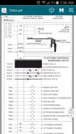
Sure they do. What switch/color wires went there? Scroll to the end of the service manual and the scroll back up till you get past the hydeauluc schematics. Find the page for your serial numbers. You can find what 2 pins are positive/negative polarity to match up to the schematic.
 

Attachments

  • Screenshot_2015-12-12-07-36-12.jpg
    Screenshot_2015-12-12-07-36-12.jpg
    12.1 KB · Views: 31
OP
J

joker2607

Member
Joined
Dec 12, 2015
Messages
5
Thank you all again for helping. This is the scheme of my controler http://postimg.org/image/6p7huvsdt/

I know how the wires go but if you look at it carefully on the scheme i can't figure out where do these holes connect to(holes 3 and 5) it says here PIO3 PIO4 PIO5 but I don't know what are those, I don't know where to connect them.
 

Skidonenko

Well-known member
Joined
Jan 19, 2014
Messages
54
Location
Dallas area
what is on the other end of the wires? switches? travel pot? LED's? Do you have 5 wires that went to that connector? does it have outriggers?
 
To avoid these ads, REGISTER NOW!

Skidonenko

Well-known member
Joined
Jan 19, 2014
Messages
54
Location
Dallas area
I would probobly replace that card. It looks like there is a small wire/trace on the top of that third pin that goes to that little tan/brown component. Did you solder the wires directly to the card? If the joystick harness checks good (POT and switches) then something on the card sounds damaged. Kinda ***** not having it to put my eyes/hands on.
 

redmondjp

Well-known member
Joined
Nov 25, 2014
Messages
2,318
Location
Redmond, WA
You probably have a broken trace on the circuit board. This can be difficult if not impossible to see (from lots of personal experience). If you have an ohmmeter, I would ohm out all of the traces on that part of the board - note that there is a clear colored coating over most of the traces, and possibly a protective coating over the entire board that you must punch through with the test probes in order to make good contact.

Also, there are third-party companies that will repair these controls - they can be found on the web. Many rental companies utilize their services as it is often far less expensive than buying OEM replacement parts which have a 400% markup (I used to work at Genie - a joystick that we bought for $200 would be sold for $800 to our customer).
 

Skidonenko

Well-known member
Joined
Jan 19, 2014
Messages
54
Location
Dallas area
You probably have a broken trace on the circuit board. This can be difficult if not impossible to see (from lots of personal experience). If you have an ohmmeter, I would ohm out all of the traces on that part of the board - note that there is a clear colored coating over most of the traces, and possibly a protective coating over the entire board that you must punch through with the test probes in order to make good contact.

Also, there are third-party companies that will repair these controls - they can be found on the web. Many rental companies utilize their services as it is often far less expensive than buying OEM replacement parts which have a 400% markup (I used to work at Genie - a joystick that we bought for $200 would be sold for $800 to our customer).

Truth! Lol. Flight systems for amps/controllers. Might give them a ring.
 
OP
J

joker2607

Member
Joined
Dec 12, 2015
Messages
5
I would probobly replace that card. It looks like there is a small wire/trace on the top of that third pin that goes to that little tan/brown component. Did you solder the wires directly to the card? If the joystick harness checks good (POT and switches) then something on the card sounds damaged. Kinda ***** not having it to put my eyes/hands on.

The machine has outriggers. I tried to connect the wires directly to the board but it's impossible, then i searched for the trace where would they be connected and I found the 1,2,4, but the 3 and 5 no luck. The wires on the other end go to the connector which goes to ECM.


redmondjp if you have any source for these parts that would be great if you guys are sure that it's the board, because I don't want to change it if it's not.


Thank you for all the answers
 
OP
J

joker2607

Member
Joined
Dec 12, 2015
Messages
5
Hii all, after replacing the card, the machines shows the same fault code 02. The cable is ok. After I turn the key to platform control the joystick lights blink and then turn of. What should I do, my machine is out of order now for 20 days, please anyone?
 

redmondjp

Well-known member
Joined
Nov 25, 2014
Messages
2,318
Location
Redmond, WA
You may have a short in the platform controls then - so when you switch over to platform, the controls detect this short and then the power is turned off to protect the output drivers.

You do have the E-stop pulled up on the platform controls, correct?
 

914wilhelm

Well-known member
Joined
Oct 6, 2010
Messages
190
Location
Columbia Gorge, Oregun
Did you check the individual cable conductors had continuity from end to end?
Did you check the cable had no shorts between individual conductors?
Did you check none of the cable conductors shorted to ground?
Did you verify the cable connectors have continuity through their jacks to the pcb after the connector was ripped free?
 
To avoid these ads, REGISTER NOW!
Top Bottom