To avoid these ads, REGISTER NOW!

Old Fart Cart?

To avoid these ads, REGISTER NOW!
OP
J

Jeff Ivers

Well-known member
Joined
Apr 9, 2010
Messages
2,565
Location
Oklahoma
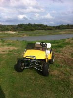
Great video. Thanks for posting. However, that does not qualify as an Old Fart Cart since its use would not be allowed at the large swap meets that I have been to.


Get with the times. Sorry about the cackling B00B. It's all I could find quickly :sad:
 
OP
J

Jeff Ivers

Well-known member
Joined
Apr 9, 2010
Messages
2,565
Location
Oklahoma
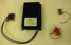
OFC controller.JPG
This is a picture of the controller I bought for my OFC. It is from 4QD in the UK. The reasons I went with this:
Unable to locate used controllers with sufficient info on them.
Programmable, which should allow me to tweek things a bit.
Handles sending a brake release signal and forward/reverse.
The item to the left of the controller is the display unit for fault codes and the programming switches. To the upper right is a LED battery power indicator. To the lower right is a plunge potentiometer, which should allow me to set up a "gas pedal"
OFC chassis 5.JPG
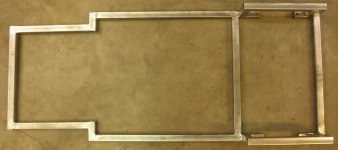
Today, I mated the front and rear chassis segments and added a couple of cross ties.
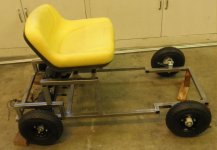
OFC chassis 6.JPG
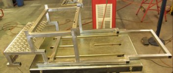
Then I started prototyping front wheel placement and seat supports. The entire area between the seat supports will be enclosed and used as the repository for the controller and batteries. The seat will be hinged at the front for access.
 

ZRX61

Well-known member
Joined
Aug 15, 2006
Messages
28,716
Location
Solar Blight Valley, SoCal
Needs a deck gun.....

https://scontent-lax3-1.**.fbcdn.net/hphotos-xaf1/v/t1.0-9/11230668_859317790823955_6671011416376435921_n.jpg?oh=b9b84e6602e6ffb90257893f74092597&oe=56E2EAF6
 

Whiskeymike

Well-known member
Joined
Oct 31, 2013
Messages
775
Location
Austin, TX
This is what I would build... Spotted this at Jeep Beach earlier this year. A guy had taken a yard cart from northern tool and married it to a scooter with a couple agm batteries. Benefits were the large tires for going over grass and gravel, and the steering already built into the cart, controls built into steering.

Your build is coming along nice. Please keep posting your progress.
 

Attachments

  • image.jpg
    image.jpg
    27.6 KB · Views: 269
OP
J

Jeff Ivers

Well-known member
Joined
Apr 9, 2010
Messages
2,565
Location
Oklahoma
Man, that one makes my head sore! Joking aside, that is an innovative approach. Perhaps, if I had been able to scrounge a cheap mobility cart, I would have gone a similar direction. As it is, I will end up with more money in this than I wanted to spend, but at least it should be what I want.

This is what I would build... Spotted this at Jeep Beach earlier this year. A guy had taken a yard cart from northern tool and married it to a scooter with a couple agm batteries. Benefits were the large tires for going over grass and gravel, and the steering already built into the cart, controls built into steering.

Your build is coming along nice. Please keep posting your progress.
 
OP
J

Jeff Ivers

Well-known member
Joined
Apr 9, 2010
Messages
2,565
Location
Oklahoma
Needs a deck gun.....

https://scontent-lax3-1.**.fbcdn.net/hphotos-xaf1/v/t1.0-9/11230668_859317790823955_6671011416376435921_n.jpg?oh=b9b84e6602e6ffb90257893f74092597&oe=56E2EAF6

That looks more like a walker, but it sure is cute - built for an ex Navy person I'll bet.
 
OP
J

Jeff Ivers

Well-known member
Joined
Apr 9, 2010
Messages
2,565
Location
Oklahoma
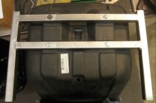
The latest progress consists of completing the seat frame.
OFC seat frame 2.JPG
The progress was slowed by the fact that, even though I thought I had things clamped up in alignment, once welded, one of the long arms was about 3/8 inch out of alignment in two directions. Fortunately my grinding skills are better than my welding skills, so I cut apart two of the welds, re-clamped, and then then re-welded, resulting in an aligned bracket. The alignment is important as I intend to have this bracket hinged for access to the area under the seat.
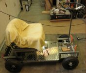
OFC chassis 7.JPG
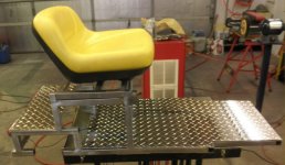
This shows the seat on its bracket sitting in the approximate final position.
 
OP
J

Jeff Ivers

Well-known member
Joined
Apr 9, 2010
Messages
2,565
Location
Oklahoma
OFC chassis 8 r.jpg
Current picture of the chassis as I start making body panels.
OFC chassis 9 r.jpg
Rear view showing LED tail-lights.
OFC chassis 10 r.jpg
Floor installed and seat mounted.
OFC chassis 11 r.jpg
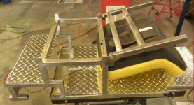
Showing the seat tilted forward to provide access to under the seat where the batteries and controller will reside.
 
OP
J

Jeff Ivers

Well-known member
Joined
Apr 9, 2010
Messages
2,565
Location
Oklahoma
I bought this for running around the ranch and visiting the neighbour across the road....0 to 20 in 3 seconds..lol.

That's a great solution for running around your property. Unfortunately, some of the places I want to use my OFC would not allow a golf cart.
 
OP
J

Jeff Ivers

Well-known member
Joined
Apr 9, 2010
Messages
2,565
Location
Oklahoma
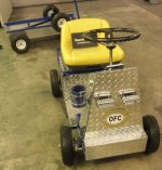
Chassis 12 r.jpg
Over the last few days, I have finished cutting and fitting the body panels with the exception of a small cutout on each side panel to clear the motors.
Chassis 13 r.jpg
This is the rear view.
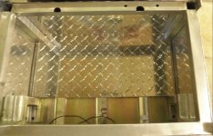
Chassis 14 r.jpg
This shows the electronics compartment under the seat.
Chassis 15 r.jpg
Showing the planned location of the batteries.
Chassis 18 r.jpg
Today, I finally welded the front spindles on the chassis and now have 4 wheels on the ground!

Tomorrow, I will start working on the support structure for the steering, clearance the side panels for the motors and put some thought into "gas" pedal placement.
 
OP
J

Jeff Ivers

Well-known member
Joined
Apr 9, 2010
Messages
2,565
Location
Oklahoma
Over the last few days, I have made tie rods, made a steering arm, and begun laying out the steering support structure.
chassis 19 r.jpg
This side view shows the frame structure to support the steering, and the steering column and wheels setting in place. This is mockup mode. The steering shaft has now been shortened by 3" and it will be tilted to the rear by about 5 degrees.
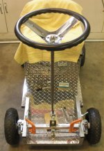
chassis 20 r.jpg
This front view shows the tie rods and steering arm. The c-clamps are holding the cross piece that will support the bottom of the steering shaft. I did this to prototype placement.
chassis 21 r.jpg
This side view shows the supports for the dash and upper steering column support. This is my first attempt at using compound angles in metal fabrication - we'll see how this comes out. The front supports are leaned back about 5 degrees.
chassis 22 r.jpg
This front view shows that I have leaned all the supports in about 10 degrees. Width of dash will be 10" and the width at the base of the supports is 15". Tomorrow, I will clean up these pieces of metal and smooth my welds, then work out the angles to cut/grind the tops of the supports to hold the dash.
 
OP
J

Jeff Ivers

Well-known member
Joined
Apr 9, 2010
Messages
2,565
Location
Oklahoma
Since my last post, I have finished the steering support structure, made a dash, and started wiring the OFC.

When I started the wiring, I ran into a temporary roadblock that required some additional research and decision making. The first issue was the battery and motor connections on the controller are 3/8 inch wide spade connectors (male). The motor wires (10 gauge) were terminated in 1/4 inch wide female spade connectors. Of course, my stockpile of parts did not include the needed connectors. Finally tracked them down at a NAPA store.

The second issue was battery cables. I had assumed I would use some #4 welding cable to make battery cables. However, I was unable to locate connectors to connect to the controller that would fit that wire size. After a bunch of research, I finally discovered a parts place selling an original Hoveround MPV5 battery wiring harness with integral 40 amp fuse. This told me the motor pair is not expected to exceed 40 amps and further research showed me 10 gauge wire would be more than adequate for the lengths I need. So that is what I will use.

The third issue was wiring the charger. I had acquired a 24 volt charger that comes wired to an XLR plug and bought an XLR socket. Which of the three pins is used and which needs to go to the positive battery lead? After further research, I determined pin 1 is positive, pin 2 is negative and pin 3 is not needed. I ended up ordering a new XLR socket that is prewired due to the wimpy nature of the pins on the socket I had already acquired.

The fourth issue is lighting. Since the cart will be used outside at all-day swap meets, I had decided I wanted to set it up with lights. I found some great LED driving lights and clearance lights (for taillights). Of course these are 12 volts. After some careful thought, I have decided it is unlikely that either the motors or controller are connected to ground since the controller reverses voltage to the motors for reverse. So, I am going to use a separate Li-ion 12 volt battery grounded to chassis to power the lights.

OFC dash 3.JPG
This is my dash. At the lower right is a 5 LED battery strength indicator. The the left of that is the keyed ignition switch. On the left side are a pair of rocker switches, one for lights and one for reverse. At the top is the bike computer I am installing for speedometer, odometer, and time functions.

OFC wiring 1.JPG
This shot shows the motor wires routed thru the panel into the battery/electronics compartment. It also shows the taillight wiring routed thru the panel.

OFC wiring 2.JPG
This shot shows the controller mounted inside the battery/electronics compartment.

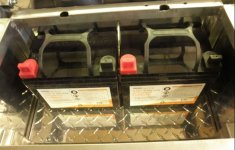
OFC wiring 3.jpg
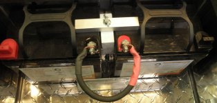
This shot shows the batteries mounted with my fabricated hold-down. I used #4 cable to connect the 2 batteries.
 
OP
J

Jeff Ivers

Well-known member
Joined
Apr 9, 2010
Messages
2,565
Location
Oklahoma
Almost done! I have finished the wiring of the OFC.
OFC wiring 5.jpg
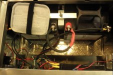
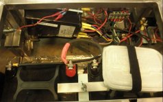
The plastic container in the upper right corner that is velcroed onto the battery contains the programming display and switches. I want to have it in the compartment and protected from the weather until I am comfortable with the programming of the controller. On the lower left side, you can see the back of the circuit breaker installed in the panel.
OFC wiring 6.jpg
This is the back side of the electronics.battery compartment. On the left is the back side of the charging port.
transmission hump.JPG
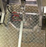
I decided I needed a "transmission hump" in which to route the wiring, as I did not want any wiring routed under the floor pan. The junction strip will be covered by the throttle plate.
chassis 25.jpg
This shows the completed "drivers compartment" with the foot-operated throttle.
chassis 26.JPG
This is a closeup of the throttle plate.
chassis 27.JPG
The completed cart up on blocks in preparation for programming the controller.
weigh-in 1.JPG
Today I weighed the cart and was delighted to find that my total weight is a mere 143 pounds with both batteries installed. (after deducting the weight of the support straps). I still have to add the battery to run the lights, and may add fenders and a couple of additional body panels. That will wait until I have test run the OFC and then disassembled it for chassis painting or powder coating.
 
OP
J

Jeff Ivers

Well-known member
Joined
Apr 9, 2010
Messages
2,565
Location
Oklahoma
It's alive! Test ran the OFC this morning. I initially had it up on blocks when I first turned on the key. Power came on, wheels turned, throttle worked - so I took it off the blocks and got on for a ride. Pressed the go pedal and it did not seem to want to go anywhere - forward or reverse. Then I realized the wheels were trying to turn in opposite directions. I had tested the motors and written down which color wire had to have + voltage to turn clockwise and then forgot that one motor would have to turn clockwise and one counter-clockwise to go forward. Switched a couple of wires and - Bob's your uncle. Next up is an extensive test drive to test longevity of charge and grade pulling and then it will be time to disassemble and have the chassis powder coated.
 
OP
J

Jeff Ivers

Well-known member
Joined
Apr 9, 2010
Messages
2,565
Location
Oklahoma
The OFC has had a trial run through the neighborhood (resulting in its first flat tire!) and been to its first swap meet. So far I have seen about 5.6 mph on level ground and 6 mph on a downgrade. It has handled local street grades fine, but not yet been tried on steep grades.
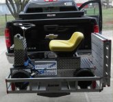
Loaded old-fart cart r.jpg
This pic shows it loaded on the OFC carrier ready to leave for a swap meet.
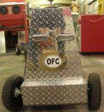
OFC name sign r.jpg
Mu daughter bought me a custom decal for Christmas, so I had to make a backing plate and mount it on the front of the cart. This also shows the additional body panels made to cover the wiring and steering linkage.
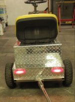
OFC tailights r.jpg
This shows the working taillights and the tow bar for the swap meet cart. This also shows the under seat panel made to cover the electronics compartment and keep it fairly dry.

I am still working on the cargo area. I had to abandon the idea of a tilting cargo bed. I am also starting on fenders. I have held off on disassembly for powder coating until I have these items more final.
 
To avoid these ads, REGISTER NOW!

why worry

Well-known member
Joined
Oct 3, 2014
Messages
301
Awesome build. Any idea as to how long the batteries will last yet?
Why worry
 
OP
J

Jeff Ivers

Well-known member
Joined
Apr 9, 2010
Messages
2,565
Location
Oklahoma
Awesome build. Any idea as to how long the batteries will last yet?
Why worry
The Hoveround MPV5 that I acquired the batteries from is rated at 12 hours with 2 31 amp hour batteries. I installed 2 35 amp hour batteries. I don't expect there to be any significant current drain issues from any other components, so I am expecting to be able to drive it all day at a swap meet without a stop for a charge. I am anxious to get an opportunity to test this.
 
OP
J

Jeff Ivers

Well-known member
Joined
Apr 9, 2010
Messages
2,565
Location
Oklahoma
After sorting out a minor wiring problem with the tail-lights, it was time to finish the cargo area.
OFC cargo 1 r.jpg
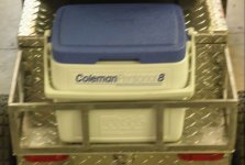
I ended up making a new, slightly longer, deck plate and adding the railing shown.
OFC cargo 2 r.jpg
Perfect fit for an ice chest, which is what I need at these huge swap meets.

As the next stage of my testing, I loaded up last Friday and headed to Canton, TX for First Monday's Trade Days. This is the largest flea market I am aware of and longest running venue in the US. I unloaded the cart and drove 3.8 miles, seeing maybe a third of the area - when the cart died! Actually, shortly after I started, I heard a squealing type noise, got off the cart, moved both the manual brake release levers to the on position and then back off. This happened several times before the cart died. Unfortunately, the controller was throwing an error code and I had not brought the manual and did not have the codes memorized.


After returning home, I determined that the brake controller on the left motor had shorted out.

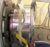
OFC short r.jpg
If you look close, this shows the melted wires.

The good news is the controller did its job. If I had had my instructions with me, I could have disconnected the one brake controller and kept going. Yesterday, I went ahead and disassembled the cart and took all the chassis bits in this morning for powder coating.

Back to the brake issue. The wires were cable tied tightly to the hub of the brake controller. Were they too tight? Did the brake module simply fail, allowing the brakes to drag and create heat resulting in the short? If anyone is familiar with these units, I would appreciate any input you have. Are the brake controllers rebuild-able, or should I simply find another unit? Thanks, in advance, for any help.
 

Craptain

Well-known member
Joined
Apr 18, 2013
Messages
4,029
Location
Tampa Bay FL
Unfortunate occurrence but still almost 4 miles for the first run is not to be discounted. At least you have proven the system. How were the batteries holding up?
I don't know anything about the motor but someone will jump in soon.

Sent from my LG-D801 using Tapatalk
 
OP
J

Jeff Ivers

Well-known member
Joined
Apr 9, 2010
Messages
2,565
Location
Oklahoma
Unfortunate occurrence but still almost 4 miles for the first run is not to be discounted. At least you have proven the system. How were the batteries holding up?
I don't know anything about the motor but someone will jump in soon.

Sent from my LG-D801 using Tapatalk
Batteries are holding up fine. I have a 5-LED battery condition meter. All 5 LEDs were still lit after about 3 hours and 3.8 miles. I am still expecting to be able to go around 12 miles and 10 hours.
 
OP
J

Jeff Ivers

Well-known member
Joined
Apr 9, 2010
Messages
2,565
Location
Oklahoma
I haven't posted an update on here since April, following a trip to a huge flea market, where the cart failed after about 4 miles. Since I didn't have any plans for any other huge swap meets or flea markets, this project slid to the back burner while I worked on other projects.

In the interim, I did determine that one of the brake controllers had melted the insulation on the wires, resulting in a short. Perhaps that is why I acquired that pair of motors and brake controllers for $40? After determining that a replacement controller would cost as much as another pair of used motors and controllers brake controllers, i went that route.

My testing of these motors has consisted of applying 20 volts to the brake controller leads to verify that the brake releases and applying 20 volts to the motor to verify that it turns. It has been too many years since my college electronics courses, I have forgotten a lot of what I might once have known, so I can't think of any other tests to perform.

I installed the replacement left motor and brake controller and then attempted to run the cart. I first got error codes from the 4QD controller that indicated a burned out fusible link on the circuit board. Their instructions told how this could be checked for and replaced with a short length of a specific gauge of wire. This I did.

Next the controller threw error codes indicating problems with the throttle pot.

At this point, I was lost, as I had no specs for the pot or controller that I could test. So, I ponied up the bucks for a replacement controller and pot (ouch!).

I installed the new controller. My thinking was that if the fusible link was blown, then perhaps something else on the board was damaged leading to the pot error codes.

Before applying power to the controller, I used my multimeter to check reading between leads on the new pot compared to the existing pot. They were quite different, so I contacted the 4QD support folks with the info and they indicated my current post is bad. I have installed the new pot.

Tomorrow, I will apply power to the controller for the first time and attempt to program it for use.

Rant time -A lot of what I do is what I call seat-of-pants engineering. I enjoy this, but at times I hate it. Why did I have a triple failure - motor brake controller, cart controller and pot? I understand how the melting of the insulation on the brake controller led to a short that affected the cart controller. What caused the brake controller to overheat? And why did the pot fail? I have checked all the specs I can think to check and this 4QD controller should be more than up to the task of managing the pair of hoveround motors and their brake controllers. I have triple checked the wiring and all matches the provided wiring diagram. When I first built the cart, I failed to make sure all the terminals being plugged into the 4QD were fully insulated. I have now corrected this.

So tomorrow, I find out if this is going to run. Any ideas on my failures and anything else I may need to do to make this bulletproof, please chime in.
 
OP
J

Jeff Ivers

Well-known member
Joined
Apr 9, 2010
Messages
2,565
Location
Oklahoma
Since my last post, I have determined the cart does run with the new controller and plunge pot. I shipped the old controller and pot off to 4QD in England.

I must post kudos here to the 4QD folks. They have been great to work with and very helpful. They helped me determine the old pot was bad and have confirmed. They have determined that my old controller is fine with the installed shunt, but are going to replace that with a self-resetting fuse, before shipping it back to me.

With the cart running, I turned my attention to a couple of improvements.
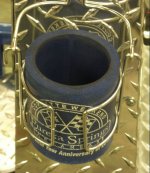
OFC cup holder 2 r.jpg
OFC - cup holder r.jpg
I added a nautical cup holder!

Since I had experienced one flat tire and had determined that the tires and tubes on those Harbor Freight 10" wheels are pretty thin, I went looking for something different. I located solid tires in the same size and installed them in place of the pneumatic tires. Yesterday, I drove to Chickasha, OK and used the cart all day at a swap meet.

On the way home, it drizzled all the way (not forecast), and, of course, the OFC was on the OFC carrier on the back of the pickup. Since we don't know why the pot failed, water intrusion was suggested as a possible culprit.

When I got home, I immediately rolled the cart into the shop and started inspecting.
OFC - rain 1 r.jpg
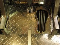
This photo shows the water beaded on the seat, floorboard, dash, etc. If you look close, you will notice the upper 2/3 of the foot pedal is dry.
OFC - rain 3 r.jpg
This is the under-seat compartment that holds the batteries and most the electronics. Everything is bone dry!
Ofc - rain 4 r.jpg
This is a closeup of the pedal showing how dry the upper portion is.
OFC - rain 6 r.jpg
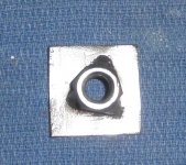
This pic, with the pedal folded up out of the way, shows how the pot is mounted in the floor so the top of the pot is proud of the floor.

The only way water could get into the pot, is if it blew sideways through a very small opening between the floor and the bottom of the pedal, hit the shaft, and then ran down it into the pot. The shaft was dry. I do not believe water intrusion caused the failure of the old pot.

Today, without recharging the batteries, I drove the cart over to get a haircut (about a mile each way). I discovered that when both green LEDs on the battery charge indicator go out, I have about .5 mile of travel remaining - didn't quite make it home. I also discovered that a couple of my tires flat-spotted. I hope that will smooth out with further use, otherwise I may have to go back to the pneumatic for a smooth ride.
 

madoc1

Well-known member
Joined
Dec 11, 2012
Messages
1,242
Location
spicewood, tx
great build! on the batteries, you should charge them after almost any use. this will prolong their life a lot. there is a lot of good info on batteries, controllers, etc. over at buggiesgonewild.com. anyway, nice ride.
this is my ofc.

jim
 

Attachments

  • oct 20011 068.jpg
    oct 20011 068.jpg
    147.7 KB · Views: 89
Last edited:
OP
J

Jeff Ivers

Well-known member
Joined
Apr 9, 2010
Messages
2,565
Location
Oklahoma
great build! on the batteries, you should charge them after almost any use. this will prolong their life a lot. there is a lot of good info on batteries, controllers, etc. over at buggiesgonewild.com. anyway, nice ride.
this is my ofc.

jim

Jim, good advise on the recharge. That is what I normally do, but in this case I was wanting to get an idea of how to use this battery meter before I go to a 300 acre swap meet and let it run out of juice at the farthest point from the truck!

That is a great looking cart you have. Looks kinda like a golf cart with atv suspension. Did you build it?
 

madoc1

Well-known member
Joined
Dec 11, 2012
Messages
1,242
Location
spicewood, tx
jeff, i understand what you are saying. where is the swap meet? yes i built the cart. stared with a 98 ezgo medalist and added ifs with a 5" lift, a lsd diff, disc rear brakes, and upped from 36 volts to 48 volts. thx for the compliment.

jim
 
OP
J

Jeff Ivers

Well-known member
Joined
Apr 9, 2010
Messages
2,565
Location
Oklahoma
Jim,

I was referring specifically to the First Monday Trade Days in Canton, but have also been to Hershey Fall, Carlisle, and Pate.

Jeff

jeff, i understand what you are saying. where is the swap meet? yes i built the cart. stared with a 98 ezgo medalist and added ifs with a 5" lift, a lsd diff, disc rear brakes, and upped from 36 volts to 48 volts. thx for the compliment.

jim
 

Playwme

Well-known member
Joined
Sep 13, 2012
Messages
2,032
Location
The Lucky Country Down Under
So I had a no go issue with my Mobility scooter converted to a go kart which uses a similar motor to what you have. It's single motor only and wouldn't go one day after sitting for a week. Turns out the brake component of the motor had rusted up. Is it possible one of your motors did that, and the extra current needed to overcome the dragging caused some issues with the controller and pot?
 
OP
J

Jeff Ivers

Well-known member
Joined
Apr 9, 2010
Messages
2,565
Location
Oklahoma
So I had a no go issue with my Mobility scooter converted to a go kart which uses a similar motor to what you have. It's single motor only and wouldn't go one day after sitting for a week. Turns out the brake component of the motor had rusted up. Is it possible one of your motors did that, and the extra current needed to overcome the dragging caused some issues with the controller and pot?

In my case, I disassembled the cover to the end of the motor and found no signs of rust - just the melted wires to the brake controller where they were clamped to the controller with a zip tie. I have just heard back from 4QD and they disassembled the bad pot and discovered pitting on the contact track at the zero throttle position. They have speculated water intrusion or vibration. I have pretty much ruled out water intrusion. Vibration is unlikely as the unit would be at rest when the throttle is at zero. I am wondering if I am getting a slight sideways load as I start to press on the throttle, that might have caused the problem.
 
OP
J

Jeff Ivers

Well-known member
Joined
Apr 9, 2010
Messages
2,565
Location
Oklahoma
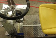
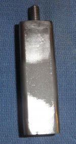
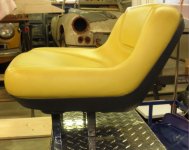
After playing with my OFC for a while, I decided it might be more comfortable if I raised my **** about 3", so, I fabbed some risers and installed them.
end cap with nut.JPG
endcap with bolt.JPG
standoff r.jpg
OFC seat risers r.jpg
OFC with raised seat r.jpg
 

Ole Slewfoot

Well-known member
Joined
Feb 22, 2016
Messages
5,098
Location
Freedom, CA
I don't think I still have any pictures, but we made one sarting with a power wheelchair, cut off the excess and channeled a LaZBoy recliner over it. Not wanting to invest much in electronics, we got a radio and 2 servos from the hobby store, attached them to the control joystick, and hid that under the body.
Much hilarity ensued. Kids face when a recliner rolls up to them on the street, pricelss.
 
OP
J

Jeff Ivers

Well-known member
Joined
Apr 9, 2010
Messages
2,565
Location
Oklahoma
I don't think I still have any pictures, but we made one sarting with a power wheelchair, cut off the excess and channeled a LaZBoy recliner over it. Not wanting to invest much in electronics, we got a radio and 2 servos from the hobby store, attached them to the control joystick, and hid that under the body.
Much hilarity ensued. Kids face when a recliner rolls up to them on the street, pricelss.

That is funny! Did you ever try touring one of the nursing homes in it?
 
To avoid these ads, REGISTER NOW!
Top Bottom