
You are using an out of date browser. It may not display this or other websites correctly.
You should upgrade or use an alternative browser.
You should upgrade or use an alternative browser.
What type crimpers are required for... ?
- Thread starter bp460
- Start date
F150tech
Well-known member
Ditch those connectors, use the metal **** terminals and heat shrink, that's what I do at work and yes I work for a ford dealer
Thanks for the replies. In the past, for this type of repair, I have always pushed the wires together end to end so they meshed and then twisted them for a stong mechanical connection. I then followed up with solder and heat shrink tubing, but this heavier gauge wire doesn't twist quite as nice. I have always been a bit leery of the common crimp connector... any recommendations for some high quality crimp connectors?
Thanks,
Brad
Thanks,
Brad
jobo1004
Well-known member
They have a minimum order of 10 and not sure what shipping would be, but I'm a fan of this style of connector.
https://www.waytekwire.com/item/38263/External-Step-Down-****-Vinyl/
https://www.waytekwire.com/item/38263/External-Step-Down-****-Vinyl/
454ragtop
Well-known member
If Ford supplied those crimps, they can't be all bad. I'd crimp them with the part of the crimper meant for ignition wires, then solder and shrink tube them.
HTH, Jim
HTH, Jim
Rookie2
Well-known member


theoldwizard1
Well-known member
Low voltage application only.Thanks for the replies. In the past, for this type of repair, I have always pushed the wires together end to end so they meshed and then twisted them for a stong mechanical connection. I then followed up with solder and heat shrink tubing, ...
I lay the stripped ends of the wire coming from opposite direction side by side. If there is a difference in gauge make the thinner gauge longer. Twist. For wires with 3-4 gauge difference (like 10 and 16) you may have to wrap the smaller one around the bigger one. Solder is optional, but marine (double layer) heat shrink is mandatory.
It you don't want to use a "step down" **** splice, use a splice sized for the larger wire and crimp it on first. Then take the smaller wire, double or triple it and strip all of them. Twist them together, inset them into the connector and crimp.
View media item 34813
Another case where marine heat shrink is mandatory.
If you are buying insulate connectors/splice make sure you have the type where the insulation is dual layer heat shrink.
torqueman2002
Well-known member
Yes, factory connections are mechanical crimps because they are able to withstand the vibrations and flexing, in more conditions than soldered connections.Just saying there is a reason areospace repairs are done only with a mechanical crimp.
Avoid soldering
OEM service manuals, specify mechanical crimps for field repairs. They are 'better' (when properly done).
That is not to say, soldering doesn't work.
It means testing shows a soldered joint will fail in more cases than a mechanical crimp.
Just saying there is a reason areospace repairs are done only with a mechanical crimp.
Avoid soldering
A properly executed crimps works very well, but so does a proper soldered splice. For example the NASA STD 8739.4 allows solder splicing via the lash splice technique. Solder splices are easier to execute and inspect. Mechanical crimps are better for a high vibe/flex situation but require specializes tooling and inspection including pull tests with samples etc.
On a connector, crimped terminals are preferred to solder cups since that is generally a high flex area.
To the OP: use the crimpers specified by the manufacturer.
454ragtop
Well-known member
GM recommends crimp then solder. In my own experience I've seen failed crimp connections, never saw a failed solder connection.
ez-duzit
Well-known member
Just saying there is a reason areospace repairs are done only with a mechanical crimp.
Avoid soldering
This.
Avoid soldering. Use quality crimps.
bmwpowere36m3
Well-known member
- Joined
- Nov 8, 2012
- Messages
- 1,125
A properly executed crimps works very well, but so does a proper soldered splice. For example the NASA STD 8739.4 allows solder splicing via the lash splice technique. Solder splices are easier to execute and inspect. Mechanical crimps are better for a high vibe/flex situation but require specializes tooling and inspection including pull tests with samples etc.
On a connector, crimped terminals are preferred to solder cups since that is generally a high flex area.
To the OP: use the crimpers specified by the manufacturer.
+1
Not to mention, I doubt anyone at home has the specialized crimpers (which are calibrated) and MIL-grade connectors/splices. We have access to a LOT of them at work...
Were not NASA or building nuclear power-plants.... personally I've had luck with all three methods (crimp, solder and crimp/solder) for personal use. Just use a decent quality connector and crimper. Soldering takes a little more skill.
Milton Shaw
Well-known member
- Joined
- Feb 11, 2011
- Messages
- 4,857
GM had a problem years ago on temp sensors on cars having connections sealed so good that coolant would travel up the wires into the ECM and cause it to fail. They recommended cutting wire and soldering it back together to get the solder to seal the wire from coolant traveling up it. If you solder it make sure to strap it down so it doesn't move and vibrate loose.
torqueman2002
Well-known member
The cause of the coolant traveling up the strands of the wire and into the ECM, was found to be improper machining of the coolant sensor brass end.GM had a problem years ago on temp sensors on cars having connections sealed so good that coolant would travel up the wires into the ECM and cause it to fail. They recommended cutting wire and soldering it back together to get the solder to seal the wire from coolant traveling up it. If you solder it make sure to strap it down so it doesn't move and vibrate loose.
The small center tip where the cutter finished, would break off and leave a path for the coolant to travel between the strands of wire and the outer insulation.
ECMs mounted inside of the passenger compartment could have coolant collecting from this failure.
Last edited:
+1
Not to mention, I doubt anyone at home has the specialized crimpers (which are calibrated) and MIL-grade connectors/splices. We have access to a LOT of them at work...
Were not NASA or building nuclear power-plants.... personally I've had luck with all three methods (crimp, solder and crimp/solder) for personal use. Just use a decent quality connector and crimper. Soldering takes a little more skill.
Word. And I also have an E36 M3.
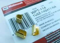
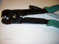
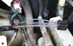
Thanks for all the replys. I performed the repair with some uninsulated **** connectors, channellock 909's and some weatherproof heat shrink tubing. I was actually more interested in learning about the crimpers required for the connectors pictured in my first post. I assume that a quality crimper like this: https://www.waytekwire.com/item/569/MOBILE-CRIMP-TOOL-KIT/ along with the proper die would do the job?
-Brad
-Brad
Attachments
Last edited:
SantaAna12
Well-known member
- Joined
- Mar 1, 2012
- Messages
- 1,091
Interesting thread.
High quality nylon connector, known quality crimper, and Marine heatshrink.
High quality nylon connector, known quality crimper, and Marine heatshrink.
owenst7
Well-known member
Just saying there is a reason areospace repairs are done only with a mechanical crimp.
Avoid soldering
Is he working on a blower motor for a space shuttle? There's a reason that aerospace isn't SAE.
Different applications call for different solutions. There is plenty of strain relief in a 8" long blower motor harness, and a lot less vibration than a plane or space shuttle. There is however, a lot of dirt, water, and other potential contaminants. I solder most splices for automotive and crimp most ends. It depends on whether you are working adjacent to a fixed point of wire. I don't care for solder connections at strain concentrations, but I also don't care for crimps in areas where harnesses will get moved around, bumped, pulled, etc. Blend door repairs or blower motor replacements can result in tugging against crimps. Combined with typical poor quality automotive wire, low voltage DC, and repeated switching, you can get oxidation at a crimp that eventually does things like burn up blower motor harnesses.
Last edited:
MFolks
Well-known member
http://www.pbase.com/image/93309736 (The good and bad of electrical crimping tools).
RichWentFishing
Well-known member
- Joined
- Feb 26, 2016
- Messages
- 48
The above link is what I found as well when researching crimpers. I'm saving my pennies for a nice set of pros kit ratcheting crimpers to redo my boat wiring.
Sent from my iPhone using Tapatalk
Sent from my iPhone using Tapatalk
Is he working on a blower motor for a space shuttle? There's a reason that aerospace isn't SAE.
Different applications call for different solutions. .
No I work on race cars and we follow Aerospace techniques to produce competition harnesses. I have seen the issues with soldered joints, often it can be an intermittent problem. The only place soldering has become used is in audio used for radio connections. The wire is soldered to pin, it is a royal pain in the *** to do, there is a product with a drop of solder in a shrink tube that is designed for this application.
But as we all know a great majority of the posters here are only looking to save money and put the problem to rest momentarily. Where I have done this for years and can not afford the risk of doing something improperly. I like to sleep at night not toss and turn wondering if the product will work correctly.
ovrrdrive
Well-known member
Thanks for all the replys. I performed the repair with some uninsulated **** connectors, channellock 909's and some weatherproof heat shrink tubing. I was actually more interested in learning about the crimpers required for the connectors pictured in my first post. I assume that a quality crimper like this: https://www.waytekwire.com/item/569/MOBILE-CRIMP-TOOL-KIT/ along with the proper die would do the job?
-Brad
Any regular crimper will work on connectors like those in the op but when working with heavy gauge wire a ratcheting or hydraulic crimper works a whole lot better. You just use the rounded (usually insulated) crimp and lightly bend down one side then flip around and lightly crimp down the other side to fold over the first, then use the crimp area for non-insulated and squeeze it down. I like the kind that punches a hole in the middle of the crimp personally for the final crimp.
Your repair looks fine to me.
Yesterday I replaced a section of a harness, about 3 feet long. It came out of the gearshifter ecu and went to the connector that contains the coil power. When shifting the power to the coils is cut by shifter ecu. The power to the coils was 7 volts with original wire. We could nt get the motor to start.The original wire was extended by cutting it and soldering an extension in the middle. So there were 2 solder joints per wire, they looked good as they were shinny and did not look brittle. Made a new wire with pins and weatherhead connector. Plugged in the new wire. the motor had not been cranked in 5 days it burst to life at the touch of the starter motor.
Going to test the original wire.
Going to test the original wire.
bmwpowere36m3
Well-known member
- Joined
- Nov 8, 2012
- Messages
- 1,125
Yup... solder is bad