I've got a couple of questions that maybe MTW can answer as they came into my head as I was reading his detailed dissertations on drain lines.
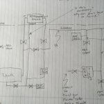
I'm planning to run a radiator on the wall behind my compressor in a vertical fashion with the bottom "U"s having a downward pointing tee and then some drain lines off of them. Because of cramped space, I have to remote the drain lines to another location about 10' away on the wall and up a few feet. If I simply fashion the drain line into a loop or like a P trap, can I then count on the air pressure driving the slug of water that distance to the valve when I open it 10' away?
Also - this brings up another question - could I not use the same technique to remote the drain for the tank itself? (It's a 60 gallon upright) - i.e. line coming off the bung on the bottom of the tank will have a bit of a P trap fashioned into it before it goes up the wall and along the wall about 8 feet away?
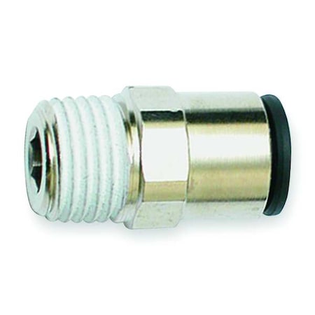
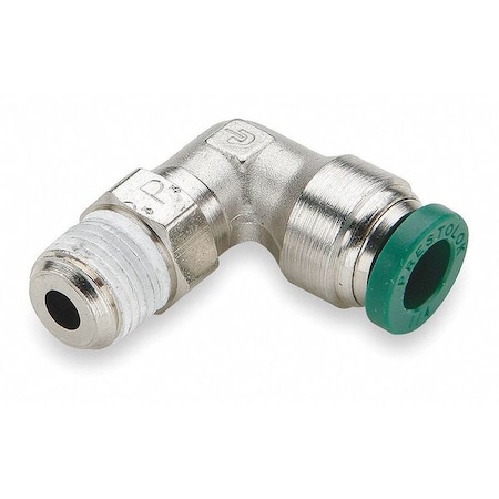
As to the drain lines themselves, I have come across a local Parker store and the lads there were showing me this push-lock hosing that, while not clear, would certainly handle the pressure for the drains - I would probably be using 3/8 or 1/4. Have not come across any clear stuff - at least with the proper fittings - yet.
Thanks again for the great thread and all the input here. It's really helped me to understand the dynamics of the situation and hopefully will save me countless hours of re-work and wasted money.
Lewis
For the vertical radiator I would build a collection manifold into the bottom of it, with the same materials used for the radiator. Use some drip leg space between the bottom collection manifold and the bottom of the return loops. You don't want your air supply ever passing over water collected in the drain manifold. Then I would slope the collection manifold to the direction you want the poly tube to head. One fitting and one tube from the radiator manifold to the drain collection system.
As to the example posted earlier, some drain point's were at floor level and about 15' away from the collection point. They were attached to the piping and went up to the main trunk line about 10' above the floor. Others originated at the trunk level, they all drained equally well. You want all of the lines the same size so that when the drain valve opens they all flow a like amount.
It will only remove the "slug" that is collected in the poly tube trap. Think of it as a pulse drain, not a continuous drain. Make all of the poly traps a similar size, don't get carried away with this. Set the drain timer for regular short pulses, not long opening times with infrequent actuation's. Long open time settings waste air, and the water slug moves quickly down the tube.
This method will work fine for all system collection points, whether high or low, it relies on the collected slug in the tube trap and pressure difference to work. Arrange the tube discharge runs to not have sags in them on the way to the collection system. Just like the air lines themselves, you want the water to flow with gravity to one end or the other, not trapped in low pockets of the tube.
In the examples shown earlier 3/8" tube was used to connect all system components, including the 300+ gallon storage tank that was more than 60 years old. The 3/8" line could handle the sludge and particulate that the tank was passing out without clogging.
The polyethylene tubing is not clear, it's whats called natural, no color added. Nylon is much tougher but not as translucent. Nylon is more amber colored and get's more so with age and use. I gave some links earlier for examples of the tubing and fittings for comparison. Parker is top shelf, but there are many manufacturers to source from. Translucent is not necessary, but is helpful in determining if the system is flowing properly.
Use brass constructed push lock fittings not plastic. It could be hazardous if someone (you) bumped into a continuously pressurized drain line or fitting and broke it off. A loose whipping plastic drain line can do some serious damage to you and the surroundings, before you know what hit you. Be sure to strap the tubing down securely to prevent it from moving in pulsating drain use, and whipping if it comes apart. Ty-rapping it securely to the air trunk lines is easy and cheap. Don't allow sags in the tubing where it will collect water and sediment. Just like the air lines, you want the water to flow under gravity to one end or the other, not trapped in the tubing.
I placed some sags in the drain tubing around the pipe unions in the main trunk piping, to have some pipe wrench room at the unions, for future service, when required. There are also some plastic 90 fittings in use at the drain manifold, but this is a restricted area in the plant and not subject to the tight quarters scenario where someone might bump it.
Go back and have a close look at the photos in post 140 and 144. It's there for you to see. Look closely, can you find all of the collection points? See the difference from before and after of the drain system? It's more meaningful to look at them again, once you read the diatribe, and understand the concepts.
Your layout is sure to be different than the one presented in the example, but the problem is the same. The concepts if applied properly and your system is plumbed correctly, should work just as effective as it did in this example. It's been many years now since this was installed, and I have yet to hear a complaint that it's not functioning as intended. The only maintenance required is to empty out the oil and water separator tank. That's on a combined 150HP screw compressor system that pumps a lot more oil into the system, than a reciprocating compressor system.
MTW Ω

 ). Interesting how great a difference there is between a polished surface and a dark/oxidized surface.

wCGk~$(KGrHqYH-C4EsMLP8z9dBLD9mku3,w~~_12.JPG?set_id=8800005007)