You are using an out of date browser. It may not display this or other websites correctly.
You should upgrade or use an alternative browser.
You should upgrade or use an alternative browser.
My attempt to make a better hose coupler
- Thread starter Leveleer
- Start date

tdkkart
Well-known member
I've never known anyone to connect a Milton style connector without pulling the ring back. Actually, didnt even know it was possible.......???
As for the rest of it Phhttt.
The Milton style has always worked just fine for me, and most people learn, by the 2nd or 3rd time, to not point the hose or tool at their face when disconnecting.
As for the rest of it Phhttt.
The Milton style has always worked just fine for me, and most people learn, by the 2nd or 3rd time, to not point the hose or tool at their face when disconnecting.
Schurkey
Well-known member
It is with some coupler brands, or it is with some plug designs. I know that some can be connected by just pushing the plug in, and some must have the ring retracted first. Perhaps it's Milton couplers vs. Generic Junk. At any rate, Milton specified "push to connect" couplers when I bought my "Universal" A-T-M coupler bodies, and again when I dumped the "Universal" for "V".I've never known anyone to connect a Milton style connector without pulling the ring back. Actually, didnt even know it was possible.......???
bigredmf
Well-known member
"If I am reading that Parker HF graph correctly, the pressure drop is around 17 PSI @ 30 CFM@90 PSI inlet pressure."
That is correct, it is rated in its dynamic state of flow.
If your picture showing your test rig is accurate you are looking at the static pressure drop.
The real voodoo in quick coupling design is in the poppets window design.
I believe you need a flow meter and tool inline of your test apparatus to actually test the coupler dynamically.
The reality is pressure drop can be mitigated with larger hoses and couplers. A impact will run dramatically better with 3/8" hose/coupling Vs 1/4". A larger impact may need 1/2 or 3/4".
If you think hose whip is a concern try it with 3/8, 1/2, or 3/4 hose and couplings.
I used to demo 3/4" couplings with a 3/4" hose both Parker safety and standard industrial interchange. You had the potential to launch a coupler through dry wall. To make it more dramatic our test rig had a 3' piece of 3/4" hose attached to the ******.
Even more dramatic is coupling two 50' hoses together with a QC. The stored energy in the 50' hose was significant.
Red
bigredmf
Well-known member

ybnormal70
Well-known member
For the win:
Coilhose Pneumatics 150USE 5-in-1 Automatic Safety Exhaust Coupler
$15 on Amazon and they work perfectly. Just check out Real Tool Reviews:
Kevin
Coilhose Pneumatics 150USE 5-in-1 Automatic Safety Exhaust Coupler
$15 on Amazon and they work perfectly. Just check out Real Tool Reviews:
Kevin
How would one achieve a pressure drop with a "static test"?"If I am reading that Parker HF graph correctly, the pressure drop is around 17 PSI @ 30 CFM@90 PSI inlet pressure."
That is correct, it is rated in its dynamic state of flow.
If your picture showing your test rig is accurate you are looking at the static pressure drop.
Red
Of course my test is dynamic. The air is flowing out a fixed orifice.
Even with my Quincy compressor running, the 60 gallon tank loses pressure fast during the test.
bigredmf
Well-known member
How would one achieve a pressure drop with a "static test"?
Of course my test is dynamic. The air is flowing out a fixed orifice.
Even with my Quincy compressor running, the 60 gallon tank loses pressure fast during the test.

The above photo appears to be a static test?
Perhaps you will share more of your test apparatus/instrumentation and procedure?
Red
Sent from my iPad using Tapatalk
Attachments

The quick answer is that the plug on the right side has an orifice reamed in it.
The above photo appears to be a static test?
Perhaps you will share more of your test apparatus/instrumentation and procedure?
Red
Sent from my iPad using Tapatalk

I can elaborate more when I have time.
bigredmf
Well-known member
You're gonna need some better instrumentation before determining your pressure drop.
I'll sit back and watch
Red
Sent from my iPad using Tapatalk
I'll sit back and watch
Red
Sent from my iPad using Tapatalk
This temporary setup does exactly what I designed it to do. No more and no less.You're gonna need some better instrumentation before determining your pressure drop.
I'll sit back and watch
Red
Sent from my iPad using Tapatalk
When and or if I'm ready to do some really scientific testing it will be done in my lab in Texas.
bigredmf
Well-known member
If your lucky those gauges are 2.5% no more probably less, of full scale accurate
Good luck
Red
Sent from my iPad using Tapatalk
Good luck
Red
Sent from my iPad using Tapatalk
Provincial
Well-known member
If your lucky those gauges are 2.5% no more probably less, of full scale accurate
Good luck
Red
At 90 psi (which is the design operating pressure of most air tools) the extreme spread would be around 2 psi, but likely much less. That is insignificant as far as air tool performance.
I don't see where laboratory quality gauges would be required at this stage of experimentation. The size of the orifice is the most critical part of the setup.
Since he is comparing his design to an existing one using the same setup, the results will be accurate for the purpose of comparison. In other words, if he shows a 10 psi drop in the factory unit and 7 psi in his design, his will have been proven to have less restriction. The only way gauge error would affect this sort of test would be to swap the gauges when changing between test couplings, which isn't happening.
bigredmf
Well-known member
He's measuring his pressure drop at less than your stated accuracy.
He has stated his design has roughly 2/17th of the pressure drop of a well known manufacturer.
Something does not add up
The quality of his "instrumentation " matters when he is making claims.
Red
Sent from my iPad using Tapatalk
He has stated his design has roughly 2/17th of the pressure drop of a well known manufacturer.
Something does not add up
The quality of his "instrumentation " matters when he is making claims.
Red
Sent from my iPad using Tapatalk
pepi
Well-known member
@6PTSOCKET you want to use Milton V -- Good air flow until you get insane amount of air/needs from the one device connected.
Funny video, and really just inventing problems that don't exist in the real world.
Maybe you don't have a connection that high where it requires you to reach UP and OVER something to connect... I can't recall EVER using a connection point so terribly mounted on the wall/anything, or not on a cord real that you can push together more at waist level near your body with ease.
I haven't been doing this forever, but int he last 18 years I've never run into anyone in the shop who's EVER complained about how hard they are to connect... now for sure people have mentioned the code whipping you, etc, but there's solutions for that too that keep the air in or have a 1' whip type that keeps the air controlled.
Not knocking your idea or fix but I just don't see it being a 'real world' problem with anyone I know who works in shops or owns shops.
Just my 02
EXACTLY !!!!!!

If you accept the Parker numbers of 17 PSI pressure drop across their 1/4 coupler @90PSI inlet @30CFM then that is interesting.He's measuring his pressure drop at less than your stated accuracy.
He has stated his design has roughly 2/17th of the pressure drop of a well known manufacturer.
Something does not add up
The quality of his "instrumentation " matters when he is making claims.
Red
Sent from my iPad using Tapatalk
If for example you are using a 3/4 impact at 90psi at the tool the flow rate would be about 30 CFM since the tool is rated about 7.5 @25 percent duty cvcle.
17 PSI drop per fitting with one on either end of a hose would be 34 plus the pressure drop across the hose could easily total over 40 PSI pressure drop.
However, since the Parker is rated at 90 PSI inlet pressure it would be worse then this.
bigredmf
Well-known member
If you accept the Parker numbers of 17 PSI pressure drop across their 1/4 coupler @90PSI inlet @30CFM then that is interesting.
If for example you are using a 3/4 impact at 90psi at the tool the flow rate would be about 30 CFM since the tool is rated about 7.5 @25 percent duty cvcle.
17 PSI drop per fitting with one on either end of a hose would be 34 plus the pressure drop across the hose could easily total over 40 PSI pressure drop.
However, since the Parker is rated at 90 PSI inlet pressure it would be worse then this.
Actually the Parker charts are at 100 and 80 psi but feel free to interpolate as you can see the linearity in the chart.
The general rule of thumb is 5 psi per fitting so any coupler would be far greater.
The graduations on your gauges are not fine enough to read 1 or 2 psi as well.
Though I applaud your efforts I am sure there are other issues with your testing methodology.
I have posted charts in an effort to help you and am unsure why you would discount the flow charts of a multi billion dollar corporation? I do not even represent their products.
If you are interested I will consult a manufacturer I represent to determine a known industry test methodology and confirm to you via pm.
Test gauging does not have to be elaborate nor expensive you could get fancy with a 12" dial and mirrored face gauges and still not be accurate or go to a differential pressure gauge with proper resolution. These items should probably be in the .5% accuracy range Vs. a no name possibly Swaziland manufactured un-calibrated pressure gauge.

My guess is you need to place a regulator or diaphragm relief valve (back pressure regulator) on the outlet after your orifice which may not be needed along with a needle valve and flow meter, locations subject to determination later.
Respectfully
Red
bigredmf
Well-known member
BTW a 3/4" impact should not be run on a 1/4" bodied quick connect.
I purchased my first impact a CP744 in 1990, 1/2" and attempted to remove lug nuts on my car. They would not come off, switched to a 3/8" hose and coupler and I am pretty sure I could break them by over tightening with that set up.
Red
I purchased my first impact a CP744 in 1990, 1/2" and attempted to remove lug nuts on my car. They would not come off, switched to a 3/8" hose and coupler and I am pretty sure I could break them by over tightening with that set up.
Red
bigredmf
Well-known member
I'll dig through my stash of air prep and see if I have anything that might help you.
It's at my office so be back to you on Tuesday!
Red
It's at my office so be back to you on Tuesday!
Red
TMcCay
Well-known member
Leveleer, after watching your videos I would be interested in your couplers to. Currently I use the Milton type "V"s and have enjoyed the increase in cfm from them over the type "M"s that I used previously. I hope that you can get these to market in the future as I would be a future customer.
Good Luck!
Good Luck!
bsaint
Well-known member
BTW a 3/4" impact should not be run on a 1/4" bodied quick connect.
I purchased my first impact a CP744 in 1990, 1/2" and attempted to remove lug nuts on my car. They would not come off, switched to a 3/8" hose and coupler and I am pretty sure I could break them by over tightening with that set up.
Red
You should've just turned up the pressure. Same reason why 480v is half the current of 240v both having the same kva. Air tools are rated at 90 PSI for the numbers game but Ive never read anywhere on my Snap-On air tools 90 psi was the maximum pressure. Its a huge chunk of cast aluminum with steel vane motor, I run all mine at 125#
Just to clear things up a bit, let me explain.
I am not in the manufacturing business anymore. I retired from that.
Currently I am mentoring a young man by teaching him about design and manufacturing.
When he started with me I was building an automatic micro drilling machine for jewelry making. Somewhere along the line I decided I had enough of air noise in my life.
I tried designing a 2 stage air compressor from the ground up and he helped me with it.
I still have it and use it occasionally. While working with it I had real problems with my hearing because of all the compressed air noise. That's when I first thought about making my own air fittings.
bigredmf
Well-known member
You should've just turned up the pressure. Same reason why 480v is half the current of 240v both having the same kva. Air tools are rated at 90 PSI for the numbers game but Ive never read anywhere on my Snap-On air tools 90 psi was the maximum pressure. Its a huge chunk of cast aluminum with steel vane motor, I run all mine at 125#
Most air tools are designed for Max 90 psi.
BTW I ran it at 130# would not break the lugs. The performance difference with air tools can be dramatic with larger bodied couplers and hose. The traditional garage in the 70's ran 5/16" ID which is not popular now so some move to 1/4" but many to 3/8", a 3/4" Impact should probably run on 1/2" hose and couplers for best performance.
Red
Attachments

ToddW
Well-known member
I won't get into Euro or Asian couplers. I'm discussing North American styles only.
There are five main styles. These four, plus ARO. I thought I had re-posed these photos to include ARO, but apparently not. These are all 1/4" bodies. There are other styles for 3/8 and larger bodies.
Milton "V" is a high-flow coupler, it may be the same as a Euro high-flow, but I haven't confirmed that. Note the larger internal diameter.
The Milton "M" is the same as "Industrial Interchange", probably the most-popular style in the USA. Compression testers, leakdown testers and other factory-made tools use the Industrial Interchange system. It's also a US Military standard. You go into some poorly-stocked hardware store, they're going to sell only the "M" style, probably as a crappy Chinese import.
The Milton "T" is a Tru-Flate style, also called "Automotive Interchange". Shortest pilot in the industry.
The Milton "L" is the Lincoln style. Longest pilot in the industry.
Not shown: Milton "A", the ARO style.


The quick-disconnect bodies can be had as "universal", by which I mean they'll accept three of the five styles. I had a "universal" body for a while, but it leaked perpetually with my "T" coupler plugs--the ones with the short pilot. I think they sealed just fine with "M" plugs, and they also fit "A", but I didn't have any of those. So the "Universal" coupler bodies fit "A-T-M" style plugs.
A coupler body that fits Milton "V" will also fit "M" (and "A"???) plugs, but with reduced flow. However, a coupler body for "M" will not fit "V".
I recently converted to Milton V couplers in my shop. IF (big IF) I was willing to stay with Industrial Interchange, my shop would be set up with TST/Oetiker B1 swing couplers. Zero insertion force (except for seal friction) and self-venting when disconnecting. They're somewhat scarce although Amazon has some styles. The B1 is compatible with Industrial Interchange. TST/Oetiker makes other styles also, so be careful.
https://www.amazon.com/dp/B000L9V74S/?tag=atomicindus08-20
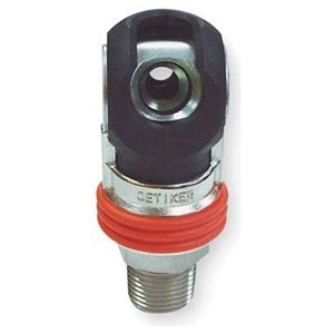
That is the exact model I was talking about.
I have a couple of those very very simple to use.
I like the Oetiker swing coupling and I will buy one to check it out.
One of the first couplings I designed back last October was also "full flow", meaning you could see straight through it when connected.
I never prototyped it as I decided it was too large and overly complicated.
One of the first couplings I designed back last October was also "full flow", meaning you could see straight through it when connected.
I never prototyped it as I decided it was too large and overly complicated.
It looks like the Oetiker swing couplers were bought out by RTC.
http://rtc-northamerica.com (USA branch, obviously)
Also:
http://www.rtc-tec.com/products?cat_id=35&p=1
Try as I might, I couldn't find a swing coupler they make that will fit the euro high flow plug (same as Milton v?). Perhaps others can find it. It looks like they definitely work with industrial interchange, among others. The catalog's language style is European, and a bit hard to figure out.
ToddW
Well-known member
I have a couple swing couplers I got from a project around 10 years ago... I don't use them actively, but I'll try them out with the various fittings I have next time I'm out there and dig them up.
I am curious as to how the swing coupling works on disconnection when connected to the pressure side of a hose. When you pull the collar back does it vent and if so do you have to hold it in the vent position until the pressure drops before swinging it to release position?
texasfiremedic
Well-known member
Frank, it's hard not to like good 'ol murican cando and ingenuity. Thanks for your sharing your efforts and progress.
It is easy to discount drama, however, whether feigned or sincere. Human kind is a cruel bunch, deeply steeped in skepticism. I suggest that you make a new video, and invite innocent, unsuspecting participants to disconnect each air line, and film them doing it for the first time, with no other instruction from you other than to disconnect the line.
Film the authentic reactions of the participants, which will sufficiently speak for themselves, without absolutely ******* the BS meter like any "look at what I made and how much better it is than anyone else's" self assessment otherwise might do.
The issue isn't that you were being overly dramatic... the issue is that your video comes across that way, no matter how you actually felt. And that first impression is going to be a difficult hurdle for some of your prospective customers to overcome.
With all due respect it sounds like a Chevy vs Ford commercial. I still think it is obvious when no one questions the weight of the "empty" tool box and why it did not dent the tool box. It may be empty but it has a heavy plate for a bottom and sides.
But to the OP's invention. Great product if ever produced. It would appeal to all ends of the spectrum from home to industrial. Needing a disconnect that is easier to push in and releases without the hose whip would be beneficial from a safety stand point. May companies spent count thousands a year just to reduce accidents. You could market it on that stand point.
Schurkey
Well-known member
Pulling the collar does NOTHING except release the lock preventing the coupler from "swinging". Once the collar is pulled, the coupler can "swing", the movement first blocks the air from the compressed-air tank through the coupler, then a little more movement vents the air from the coupler to the tool. When the coupler has swung far enough, it no longer holds the coupler plug, which can then be readily removed with no pressure behind it. Assembly is the reverse--you push the coupler plug past the rubber seal (seal friction is the only force required to insert the plug) then the coupler body swings which first locks the coupler plug in place, closes the vent, then opens the passageway between the compressed air and the plug (and onward to the tool)I am curious as to how the swing coupling works on disconnection when connected to the pressure side of a hose. When you pull the collar back does it vent and if so do you have to hold it in the vent position until the pressure drops before swinging it to release position?
The "swing" is very similar but not identical to a modern quarter-turn faucet handle--the rotating part is sealed with O-rings around the water passage, when you align the holes, water (air) flows, and when the holes aren't aligned, water (air) cannot flow. There's no vent, of course, in the water faucet.
Pulling the collar does NOTHING except release the lock preventing the coupler from "swinging". Once the collar is pulled, the coupler can "swing", the movement first blocks the air from the compressed-air tank through the coupler, then a little more movement vents the air from the coupler to the tool. When the coupler has swung far enough, it no longer holds the coupler plug, which can then be readily removed with no pressure behind it. Assembly is the reverse--you push the coupler plug past the rubber seal (seal friction is the only force required to insert the plug) then the coupler body swings which first locks the coupler plug in place, closes the vent, then opens the passageway between the compressed air and the plug (and onward to the tool)
The "swing" is very similar but not identical to a modern quarter-turn faucet handle--the rotating part is sealed with O-rings around the water passage, when you align the holes, water (air) flows, and when the holes aren't aligned, water (air) cannot flow. There's no vent, of course, in the water faucet.
Thanks for the detailed explanation.
Therefore, iif a person is in a hurry and swings it all the way open quickly then that could be dangerous if the plug is connected to a long hose under pressure. Correct?
Schurkey
Well-known member
Not a bit more "dangerous"--and almost certainly less "dangerous" (I'd have said "annoying") than disconnecting a "normal" coupler that doesn't vent before disconnecting.Thanks for the detailed explanation.
Therefore, iif a person is in a hurry and swings it all the way open quickly then that could be dangerous if the plug is connected to a long hose under pressure. Correct?
My normal mode of operation has been when disconnecting a blow-gun from a typical Milton quick disconnect, to face the blow-gun upwards, pop the coupler ring with one hand so the blow-gun jets upward, and then grab it with the other hand as it falls. Doesn't seem "dangerous" to me. When disconnecting two air hoses, with considerable stored air, yeah, it's noisy.
lol a little over dramatic to the milton v style. thats all we use in our farm shop gotta eat some more wheaties and spinach and grow a pair lmaoOne of the things I don't like about high flow compressed air couplings is the force required to engage them. The explosive decompression during disengagement is also a big problem which is at least solved by so called "safety couplers"
I played around with a few designs of my own and here is a video I made doing a quick and dirty comparison.
FWIW
IT's only a prototype.
Frank
Not a bit more "dangerous"--and almost certainly less "dangerous" (I'd have said "annoying") than disconnecting a "normal" coupler that doesn't vent before disconnecting.
My normal mode of operation has been when disconnecting a blow-gun from a typical Milton quick disconnect, to face the blow-gun upwards, pop the coupler ring with one hand so the blow-gun jets upward, and then grab it with the other hand as it falls. Doesn't seem "dangerous" to me. When disconnecting two air hoses, with considerable stored air, yeah, it's noisy.
My point was that if one swivels the coupling under pressure and swings it quickly past the exhaust position, could the plug be explosively expelled.
As a designer, I have to consider that devices will be used incorrectly.
bigredmf
Well-known member
I used the Oetiker to test leakage of hose assemblies with Nitrogen at 250 psi for years, thousands of assemblies.
The only issue we had was when a coworker had it cranked up to 1000 psi, the end did not pop off violently it was just a scary situation as he new there was a issue and called me over. The 300 psi air hose was rigid as pipe. I lowered the regulator to 250 but it was not a relieving type so I had to vent it at 1000 psi.Now the hose was only 36" long but 3/4" in diameter. With a standard QC it would have been a projectile but with the Oetiker it was not.
Red
I still would like to know what happens when you rapidly swing it past the vent position to the fully open position under pressure. I assume that the plug is ejected under pressure.I used the Oetiker to test leakage of hose assemblies with Nitrogen at 250 psi for years, thousands of assemblies.
The only issue we had was when a coworker had it cranked up to 1000 psi, the end did not pop off violently it was just a scary situation as he new there was a issue and called me over. The 300 psi air hose was rigid as pipe. I lowered the regulator to 250 but it was not a relieving type so I had to vent it at 1000 psi.Now the hose was only 36" long but 3/4" in diameter. With a standard QC it would have been a projectile but with the Oetiker it was not.
Red