The reason that a 30A breaker w/ 14 AWG is code compliant is that the compressor has overload protection so the breaker is only for short circuit protection, and and art 430.6 allows the values in table 310.15(B) which means 14 AWG, is 20A, 12 AWG, is 25A, & 10 AWG, is 35A, if NM cable "Romex®" is used the above values do not apply though. All being said I would use 12 AWG because only like 14 for residential lighting, or control wiring.

You are using an out of date browser. It may not display this or other websites correctly.
You should upgrade or use an alternative browser.
You should upgrade or use an alternative browser.
Wiring for a new A/C condenser
- Thread starter Junkman
- Start date
ard
Well-known member
The motor will not draw that current long enough to cause an issue on #14 wire.
It still causes me to squirm though. As a non-electrician I size the wire by the breaker, works for me.
It still causes me to squirm though. As a non-electrician I size the wire by the breaker, works for me.
Radix2
Well-known member
I don't know enough to disagree, and I would like to learn. I know that the breaker is designed to protect the wiring, and that a 20 amp GFIC requires a 12 gauge wire, so what I don't understand, is why the A/C unit that has a 30 amp breaker because of higher starting current draw, can use a 14 gauge stranded copper wire. I also understand that stranded wire can carry a larger amount of current than a solid wire, but I didn't think that it was that great of an amount, that you could reduce the wire size to that degree. I will accept that you folks understand this code requirement better than most, and I will follow your advise. Now, I have a couple of additional questions. The gauge of the feeder wire from the 30 amp breaker in the panel to the junction box where the stranded copper wire will be joined, is that 14 gauge nonmetallic sheathed wire, or does it need to be larger? Same question for the 20 amp GFIC line, what size stranded, and what about the feeder wire?
The reason a defined load like a a/c unit has different wiring requirements is just that - unlike a plug/general purpose circuit that has no engineered electrical characteristics, the defined load is a known and fixed quantity.
(The same rationale is used for the cords on devices) - the designer can look at how the device operates, the load vs time, possible failure modes, etc. and can decide that it will not operate at high currents for long periods that would overheat the wiring - and in the case of failure will have high currents that can clear the specified fusing easily.
In the case of normal 12g/20a, 14g/15a wiring, there needs to be margin put in because the combination of devices may continuously load the circuit at its limit, driving heat into the wiring and connections.
Heat is the ultimate failure mode to be avoided, for a known device with peaky but short duration use, much smaller wiring and bigger fuses can be used.
Thanks for the explanation, and now I fully understand the logic behind the smaller wire. Now, I will pose another question. The whip that I purchased came in either #8 or #10 wire. Why don't the manufacturers of the whips, off them with smaller gauge wires to match the rest of the wiring, or do they? My old 4 ton unit was wired from the panel to the disconnect with a #12 nonmetallic interior wire, and from the disconnect to the unit, with #8 stranded wire.
Another slightly unrelated question, how far away from the unit can the disconnects be located? The reason for this question, is that there are going to be two 3 ton units installed, and I know that they need to leave enough room between the units for servicing. Because of the way that the rear of the home is configured, I was thinking of placing the disconnects side by side, or above each unit, more like at eye level.
Another slightly unrelated question, how far away from the unit can the disconnects be located? The reason for this question, is that there are going to be two 3 ton units installed, and I know that they need to leave enough room between the units for servicing. Because of the way that the rear of the home is configured, I was thinking of placing the disconnects side by side, or above each unit, more like at eye level.
wyliesdiesels
Well-known member
I don't know enough to disagree, and I would like to learn. I know that the breaker is designed to protect the wiring, and that a 20 amp GFIC requires a 12 gauge wire, so what I don't understand, is why the A/C unit that has a 30 amp breaker because of higher starting current draw, can use a 14 gauge stranded copper wire. I also understand that stranded wire can carry a larger amount of current than a solid wire, but I didn't think that it was that great of an amount, that you could reduce the wire size to that degree. I will accept that you folks understand this code requirement better than most, and I will follow your advise. Now, I have a couple of additional questions. The gauge of the feeder wire from the 30 amp breaker in the panel to the junction box where the stranded copper wire will be joined, is that 14 gauge nonmetallic sheathed wire, or does it need to be larger? Same question for the 20 amp GFIC line, what size stranded, and what about the feeder wire?
That is called the skin effect...and it doesnt typically come into play until u get into much larger gauges...
The entire circuit for the condensor can be #14. NM cannot be used outside however.
The GFCI circuit, if on a 20a breaker, will need to be #12...
I dug through my circuit breaker box, and found that I have a sleeve of 10 30 amp single breakers, but no doubles. What is the pin called that connects 2 breakers together using the hole in the breaker handle? Would it be acceptable to use a small nail that was cut to size? Thanks Junk
prostreetamx
Well-known member
Another slightly unrelated question, how far away from the unit can the disconnects be located? The reason for this question, is that there are going to be two 3 ton units installed, and I know that they need to leave enough room between the units for servicing. Because of the way that the rear of the home is configured, I was thinking of placing the disconnects side by side, or above each unit, more like at eye level.
You are required to have a 30" wide access to your electric disconnects. It doesn't matter if they are centered in that space, over to one side or stacked as long as there is nothing in the pathway in front of them. I used an exterior 6 circuit sub panel to feed both of my units. I fed it with bigger wire so I could mount the GFCI service plug on the side and still had separate 30a 2 pole breakers for the units. I used a separate 20a breaker for the service plug. The sub panel is located in the middle.
alfredeneuman
Well-known member
What is the pin called that connects 2 breakers together using the hole in the breaker handle? Would it be acceptable to use a small nail that was cut to size? Thanks Junk
It's called a handle tie, and it's not suitable for the control of line to line loads such as the condenser. They're only for the manual control of multiple line to neutral loads
2 and 3 pole breakers have an INTERNAL trip mechanism that trips the poles simultaneously
Per NEC 240.15(B) Circuit breakers shall open all ungrounded conductors of the circuit both manually and automatically
Last edited:
wyliesdiesels
Well-known member
I dug through my circuit breaker box, and found that I have a sleeve of 10 30 amp single breakers, but no doubles. What is the pin called that connects 2 breakers together using the hole in the breaker handle? Would it be acceptable to use a small nail that was cut to size? Thanks Junk
handle tie.
Nail is no good and u need common trip breaker.
What brand and model panel do u have?
It's called a handle tie, and it's not suitable for the control of line to line loads such as the condenser. They're only for the manual control of multiple line to neutral loads
2 and 3 pole breakers have an INTERNAL trip mechanism that trips the poles simultaneously
Per NEC 240.15(B) Circuit breakers shall open all ungrounded conductors of the circuit both manually and automatically

mobiledynamics
Well-known member
Thread Bump to Post 24. Solid wire OK for a condenser. On one of the condensers out hvac hooked up, the control/power line from condenser feeding the indoor unit (he must have ran short but he used solid wire). OK to leave it or should one change it all back to stranded since technically, the wiring is on a motor...
I need to know, how many wires will I need for each unit. Will it be 2 hot and a ground (Red/Black/Green), or 2 hot, 1 neutral and 1 ground (Red/Black/White/Green). Also, can the one ground (green wire) serve both units and the GFIC, or should I run 3 separate green wires? I will be using red & white for the 20 amp GFI, just also need to know about the green to the GFIC.
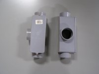
I have figured out the method that I will get the power from the cellar to the outside and then to the wall where the 2 units will be set on concrete slabs. What I am going to do is to use one 1 1/2" conduit that starts in the cellar, that presently goes up to the ground surface outside the foundation, and dig down 30", and cut it off, and install a 90 degree vertical sweep pointed away from the house, and then another 90 degree horizontal sweep that will put it in line with the back wall of the garage. The garage juts out from the house about 4 feet and the 2 units are being installed parallel with the garage wall. Once I get the 1 1/2" conduit to where I want it, I will put another 90 degree sweep onto it, to bring it up out of the ground against the garage wall. I will use a expansion slip joint sliding connector, in case there is any movement of the pipe in the ground, so it doesn't want to pull away from the wall. At that point, I will be putting a tee on top of the 1 1/2" conduit, and reduce the two ends to 1" conduit, with the appropriate piping to get into the two pull disconnects. Figuring that I will need 4 wires for each 220 volt unit (2x4=8), plus 3 for the GFIC, that will give ma a maximum of 11 wires in the conduit. I am planning on using all 12 gauge stranded in the conduit. I am hoping that the pull through the 3 90 degree sweeps will not be a hassle. Your thoughts? Sorry that I don't know all the "technical terms" for the PVC piping. thanks Junk
I have figured out the method that I will get the power from the cellar to the outside and then to the wall where the 2 units will be set on concrete slabs. What I am going to do is to use one 1 1/2" conduit that starts in the cellar, that presently goes up to the ground surface outside the foundation, and dig down 30", and cut it off, and install a 90 degree vertical sweep pointed away from the house, and then another 90 degree horizontal sweep that will put it in line with the back wall of the garage. The garage juts out from the house about 4 feet and the 2 units are being installed parallel with the garage wall. Once I get the 1 1/2" conduit to where I want it, I will put another 90 degree sweep onto it, to bring it up out of the ground against the garage wall. I will use a expansion slip joint sliding connector, in case there is any movement of the pipe in the ground, so it doesn't want to pull away from the wall. At that point, I will be putting a tee on top of the 1 1/2" conduit, and reduce the two ends to 1" conduit, with the appropriate piping to get into the two pull disconnects. Figuring that I will need 4 wires for each 220 volt unit (2x4=8), plus 3 for the GFIC, that will give ma a maximum of 11 wires in the conduit. I am planning on using all 12 gauge stranded in the conduit. I am hoping that the pull through the 3 90 degree sweeps will not be a hassle. Your thoughts? Sorry that I don't know all the "technical terms" for the PVC piping. thanks Junk
Attachments
Last edited:
While 220 volts does have a neutral it's a voltage used in 3rd world countries not the US, 240 volts does not, and 230V rated A/C condensers do not require a neutral, clothes dryers, ranges, ovens, & some cooktops do require a neutral & are rated for 120/240V, save some money & omit the neutral.
mobiledynamics
Well-known member
Can anyone shed more insight on the neutral. For example. if a 50 amp was pulled and there was a service outlet being installed, the spark pulled a 6 awg neutral. If it's just a measly service port.
Would ya'll pulled 6 wire for the measly 20 amp outlet that would never would have drawn 20 amps on the service outlet. Granted the hots were 6 awg...
Or would it just be ~weird~ to have a mismatch of 6 wire hots and 12awg white /
Would ya'll pulled 6 wire for the measly 20 amp outlet that would never would have drawn 20 amps on the service outlet. Granted the hots were 6 awg...
Or would it just be ~weird~ to have a mismatch of 6 wire hots and 12awg white /
Aceman
Well-known member
Can anyone shed more insight on the neutral. For example. if a 50 amp was pulled and there was a service outlet being installed, the spark pulled a 6 awg neutral. If it's just a measly service port.
Would ya'll pulled 6 wire for the measly 20 amp outlet that would never would have drawn 20 amps on the service outlet. Granted the hots were 6 awg...
Or would it just be ~weird~ to have a mismatch of 6 wire hots and 12awg white /
Why would a 20 amp receptacle neutral wire be connected to a 50 amp circuit in the first place?
Run a circuit for the HVAC unit.
Run a circuit for the service receptacle.
Do not mix wiring from one circuit to the other.
I need to know, how many wires will I need for each unit. Will it be 2 hot and a ground (Red/Black/Green), or 2 hot, 1 neutral and 1 ground (Red/Black/White/Green). Also, can the one ground (green wire) serve both units and the GFIC, or should I run 3 separate green wires? I will be using red & white for the 20 amp GFI, just also need to know about the green to the GFIC.
I have figured out the method that I will get the power from the cellar to the outside and then to the wall where the 2 units will be set on concrete slabs. What I am going to do is to use one 1 1/2" conduit that starts in the cellar, that presently goes up to the ground surface outside the foundation, and dig down 30", and cut it off, and install a 90 degree vertical sweep pointed away from the house, and then another 90 degree horizontal sweep that will put it in line with the back wall of the garage. The garage juts out from the house about 4 feet and the 2 units are being installed parallel with the garage wall. Once I get the 1 1/2" conduit to where I want it, I will put another 90 degree sweep onto it, to bring it up out of the ground against the garage wall. I will use a expansion slip joint sliding connector, in case there is any movement of the pipe in the ground, so it doesn't want to pull away from the wall. At that point, I will be putting a tee on top of the 1 1/2" conduit, and reduce the two ends to 1" conduit, with the appropriate piping to get into the two pull disconnects. Figuring that I will need 4 wires for each 220 volt unit (2x4=8), plus 3 for the GFIC, that will give ma a maximum of 11 wires in the conduit. I am planning on using all 12 gauge stranded in the conduit. I am hoping that the pull through the 3 90 degree sweeps will not be a hassle. Your thoughts? Sorry that I don't know all the "technical terms" for the PVC piping. thanks Junk
3 90s shouldn't be a big deal but you will also have whatever is needed inside to get to the panel.
I will be using two separate 12 gauge Romex (Red/Black/White/Copper ground) for the 2 air conditioning units, running from the electrical panel to a 4" square PVC box, and a short piece of 1 1/2" PVC pipe that will connect into a LB box in the cellar. The LB is going to be solvent welded the PVC pipe that is already in the cellar, and goes through the cellar wall, and up to the ground level in the yard. I will snip the white neutral wire, since it isn't needed at the panel, and where the Romex will terminate in the 4" PVC junction box. That way, all my colors will be consistent for the 220/240 volt lines (Red/Black/Green). I will also be putting a 12 gauge 110 volt line out to the GFIC, by using Romex to the 4" PVC junction box, and for those wires, I will use a different color for the hot, white and green for the GFIC line through the conduit. My thoughts for the different color wire, so it will be clearly indicated in the pull panel that the "odd" color is for the 110 volt GFIC receptacle. I also intend to wrap each wire with letter / number marker tape, so the next person will understand what was done.
wyliesdiesels
Well-known member
Can anyone shed more insight on the neutral. For example. if a 50 amp was pulled and there was a service outlet being installed, the spark pulled a 6 awg neutral. If it's just a measly service port.
Would ya'll pulled 6 wire for the measly 20 amp outlet that would never would have drawn 20 amps on the service outlet. Granted the hots were 6 awg...
Or would it just be ~weird~ to have a mismatch of 6 wire hots and 12awg white /
U wouldnt be able to use the #6 on the 50a circuit for the 20a outlet because the 20a outlet needs to be breakered @ 20a.
So u need to pull 2 separate circuits.
I will be using two separate 12 gauge Romex (Red/Black/White/Copper ground) for the 2 air conditioning units, running from the electrical panel to a 4" square PVC box, and a short piece of 1 1/2" PVC pipe that will connect into a LB box in the cellar. The LB is going to be solvent welded the PVC pipe that is already in the cellar, and goes through the cellar wall, and up to the ground level in the yard. I will snip the white neutral wire, since it isn't needed at the panel, and where the Romex will terminate in the 4" PVC junction box. That way, all my colors will be consistent for the 220/240 volt lines (Red/Black/Green). I will also be putting a 12 gauge 110 volt line out to the GFIC, by using Romex to the 4" PVC junction box, and for those wires, I will use a different color for the hot, white and green for the GFIC line through the conduit. My thoughts for the different color wire, so it will be clearly indicated in the pull panel that the "odd" color is for the 110 volt GFIC receptacle. I also intend to wrap each wire with letter / number marker tape, so the next person will understand what was done.
Don't waste money buying 12/3 if all u need is 12/2. Just phase tape the white at each splice or junction.
Last edited:
Part of your PVC is outdoors so NM cable can't be used, as NM cable is only permitted in dry locations, and any conduit underground or outdoors is considered a wet location.
I guess that I wasn't clear on the NM cable use. It is only being used in the cellar, to the point, where it will connect up to the 4" PVC junction box that is mounted on the cellar wall. there will be a short piece of 1 1/2" PVC pipe connecting the LB box in the cellar with the 4" PVC junction box. The 3 NM wires are terminated in the 4" PVC junction box. I will be using all 12 gauge THWN stranded wire from the 4" PVC junction box, out to the pull disconnects. I have purchased 2 pre made whips to go from the 2 disconnects to the A/C units.
Last edited:
mobiledynamics
Well-known member
U wouldnt be able to use the #6 on the 50a circuit for the 20a outlet because the 20a outlet needs to be breakered @ 20a.
So u need to pull 2 separate circuits.
Don't waste money buying 12/3 if all u need is 12/2. Just phase tape the white at each splice or junction.
Long Run to a Panel up to the roof for the condensers...
On the roof, there is a panel with breakers. I'm not paying for the material so I was just curious...was #6 pulled just because the run was a 50 amp run from main to the roof, and or if a money-conscious spark was doing it , he might have just pulled a #12 neutral JUST for the service outlet..
wyliesdiesels
Well-known member
Long Run to a Panel up to the roof for the condensers...
On the roof, there is a panel with breakers. I'm not paying for the material so I was just curious...was #6 pulled just because the run was a 50 amp run from main to the roof, and or if a money-conscious spark was doing it , he might have just pulled a #12 neutral JUST for the service outlet..
If theres a breaker panel, then u would have 4-wire feeding it- 3 #6 and a #10. The #12 for the outlet would originate in the breaker panel not the feeding panel.
Why would u run a #12 all the way from the feeding panel when u have a breaker panel on the roof?
mobiledynamics
Well-known member
Cause the only neutral neeeded would be for the service outlet ?
The prior electrical setup (electric was redone this year) had a 6 neutral as well but it was just wirenutted uptop in a nema splice box (as the loads were just distributed in a large splice box). Was just curious what would be the norm or not considering that the only neutral needed/required would just be for the service outlet .
The prior electrical setup (electric was redone this year) had a 6 neutral as well but it was just wirenutted uptop in a nema splice box (as the loads were just distributed in a large splice box). Was just curious what would be the norm or not considering that the only neutral needed/required would just be for the service outlet .
wyliesdiesels
Well-known member
I would run #6 to the neutral bar in the breaker panel, then #12 from neutral bar, ground bar and breaker to outlet.
Theres already a breaker panel so it doesnt get any easier than that.
Theres already a breaker panel so it doesnt get any easier than that.
wyliesdiesels
Well-known member
What are the "rules" for using 12 gauge solid wire in place of the 12 gauge stranded wire in conduit? I was digging through my garage, and I found some 12 gauge solid wire. Can this be used to wire the air conditioner disconnects?
u can use solid or stranded. No rule against solid in conduit...
u can use solid or stranded. No rule against solid in conduit...
As long as the solid is 10 AWG or smaller.
wyliesdiesels
Well-known member
As long as the solid is 10 AWG or smaller.
Other than bare cu used for GECs Ive never seen solid above #10...
Other than bare cu used for GECs Ive never seen solid above #10...
It was used in the past, have seen 6 & 8 AWG solid w/ TW insulation, & may have been made in 4 AWG.
wyliesdiesels
Well-known member
It was used in the past, have seen 6 & 8 AWG solid w/ TW insulation, & may have been made in 4 AWG.
Awww ok.
That wire must be stiff AF...would not want to pull that through conduit...