To avoid these ads, REGISTER NOW!

Running two 5hp air compressors so they run at the same time? Relay? Check Valves?

tlmartin84

Well-known member
Joined
Apr 23, 2012
Messages
1,085
Location
West Virginia
Okay, so when I posted my thread last year someone said two looks like it will be a headache keeping them tuned. Well it wasn't until today.........

I had them tuned to kick on within a few seconds of each other, as good as it gets with springs. With painting, cutoffs, impacts, they work great, one kicks on then the other, one shut off and then the other.

Then today I connected my pressure pot to blast. It just so happens the pot uses exactly what one pump puts out.

They cycle one time, and the one left running a few seconds after the first shuts off just continues to run until I stop blasting. Then the cycle starts over.

So here is what I have come up with:

1. Install a check valve on each tank exit. I'm not sure if this will help though? I think I will be in the same situation as above, the compressor left running will just keep pushing air.... am I right?

2. Buy and install a single switch on one of the tanks for a higher amperage unit, Say 10HP. Not code, but I have 10-2 ran to each compressor now, could I tie the 10-2 together at the switch. and then branch off to each motor??? I'm sure I could tie them into one larger breaker, but then that would allow one motor to pull more amps before tripping if there was an issue.

3. I'm leaning this way, not quite sure about it...What about a relay? IF I could find a 240V relay, I could keep two separate curcuits. Leave one machine on, the other off. Run a leg from the motor on the ON compressor to activate the relay that is on an entirely separate circuit?


View media item 68718
 
To avoid these ads, REGISTER NOW!

Lelandwelds

Well-known member
Joined
Sep 6, 2017
Messages
2,443
Location
Central Texas
I am confused. Why would you want both to start at once? That is quite a power surge at once. Duplex machines alternate starts so machines wear and cool evenly. Industrial compressors are set at different pressures to limit power use with rising and falling demand.

What is your goal?
 
OP
T

tlmartin84

Well-known member
Joined
Apr 23, 2012
Messages
1,085
Location
West Virginia
Well it would be a max surge of 60 amps, and to be honest I would only want it when I was just blasting, so I would switch prior to the relay so I could just run the one compressor.

The goal is to run them both at the same time....cycling the starts and stops would be great for the initial draw, but I am not sure it would be necessary.

Full load on one unit is 23 amps...
 
Last edited:

engineer2

Well-known member
Joined
Dec 13, 2009
Messages
11,824
Location
Chicago burbs
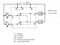
Not unusual in the industrial world to run both compressors at the same time during initial start-up or during high demand. Of course, wiring and circuit breakers have to be up to the task. Switching is often done with a cross-wired alternating relay. This type of relay alternates the two compressors to keep the hours close to each other, but allows both to run if both compressor pressure switches close.
 
OP
T

tlmartin84

Well-known member
Joined
Apr 23, 2012
Messages
1,085
Location
West Virginia
That's closer, but I still need a way to manually lock them both on. Even with that type of relay and my cfm consumption matching the compressor, the one that was running would just continue to run......
 

larry_g

Well-known member
Joined
Apr 28, 2007
Messages
16,893
Location
oregon
If the system worked for a year as you wanted it to do, and then now does not, find what changed and fix it. There is no reason to re-engineer the system. Odds are one of the pressure switches has drifted.

That said, in my opinion you do not need to both to cycle at the same time. My system when I ran multiple compressors were set at different cut in pressures. Most of the time one compressor did all the work. Only when high demand use consumed more that one compressor could keep up with would the second kick in. If I remember cut in on one was 110psi and the other was 105psi or so. I also don't think in a situation like you have that a teeter totter is necessary to run one compressor one cycle and the other the next cycle. Yes it keeps wear on each equal, but it also wears out both of them. Me I keep one like new and wear out the other. You can operate believing either scenario, your choice and reasons to do so.

lg
no neat sig line
 
OP
T

tlmartin84

Well-known member
Joined
Apr 23, 2012
Messages
1,085
Location
West Virginia
Larry, it is still working fine..........just not with my blaster.

It is coincidence I guess, but when I am blasting, the needle does NOT move on my compressor.......it won't build pressure, but it doesn't drop. So after the initial fill up, and the blaster drops them the first time, one shuts off, and then the other one just hangs running because I'm drawing off exactly what it is pumping in......it never reaches its shut off point.
 
OP
T

tlmartin84

Well-known member
Joined
Apr 23, 2012
Messages
1,085
Location
West Virginia
Just so you know I did try adjusting them. But they just flip flop, which ever one kicks at a higher pressure........just keeps running, until I stop the blaster for a few seconds.
 

engineer2

Well-known member
Joined
Dec 13, 2009
Messages
11,824
Location
Chicago burbs
That's closer, but I still need a way to manually lock them both on. Even with that type of relay and my cfm consumption matching the compressor, the one that was running would just continue to run......
Cross-wired alternating relays are also used where additional capacity is required in case of excess load requirements. Not only will this version alternate between two loads, but it also allows both loads to run simultaneously when the lead and lag switches are closed, thus providing a way for both loads to operate when running just one does not provide enough capacity.
 
OP
T

tlmartin84

Well-known member
Joined
Apr 23, 2012
Messages
1,085
Location
West Virginia
Lead and lag, those are the pressure switches? or are they manual?

If manual, that would be perfect, if they rely on the pressure switches, it won't work. Because my pressure going out is equal to whats being pumped in.
 

larry_g

Well-known member
Joined
Apr 28, 2007
Messages
16,893
Location
oregon
I do not want to be a debbie downer, but I think the way you have your system may work now, while everything is new and such. But with age it will require a lot of tinkering to keep it all in sync, to keep working the way you want it to.

Two compressor systems are nothing new, and are found in most body shops. Most have a switch that alternates the compressors run time.

While you have the ability for a lot of CFM of air, in most cases, most do not need it. If you need it then you should have a compressor, capable of pumping that CFM.

What I see is a system that will we running simultaneously, every cycle of air pressure. Not sure that is good for your load on the electrical system. Again maybe while new it will work great, but let them age a little and then it maybe a problem.

One reason for the electrical switch that alternated the compressors is one pump only runs most of the time, but you still have the volume of both tanks. If the need arises that both pumps are needed, to maintain air volume, the capability is there.

I think you have the start of a great system, but over time to keep it working as designed, it will have to be tinkered with constantly.

So has Jim's prediction from a year ago come to bear fruit?

So after the initial fill up, and the blaster drops them the first time, one shuts off, and then the other one just hangs running because I'm drawing off exactly what it is pumping in......it never reaches its shut off point

So this is why you want to make changes? Sounds very normal to me. Why do you think both units need to run and cycle on/off when one unit running does the job?

lg
no neat sig line
 
OP
T

tlmartin84

Well-known member
Joined
Apr 23, 2012
Messages
1,085
Location
West Virginia
No I don't think it has come true.......because it works now just as it did a year ago. Only difference is this is the first time I blasted it with it.

It is "normal", but why run one compressor solid for hours when you have a second setting there doing nothing?

At least give them a chance to cool off........
 

metlmunchr

Well-known member
Joined
Sep 10, 2011
Messages
1,280
Not sure what you're trying to do, but if you want to have the option of running one compressor or the other, or both at the same time, here's what you could do.

Tie both compressor tanks together, and let one pressure switch control both. But use the pressure switch for pilot duty rather than for full starting duty.

Buy 2 of these https://www.amazon.com/dp/B008KNAO96/?tag=atomicindus08-20 , 2 double pole single throw toggle switches, and a suitable enclosure.

Power wiring to each compressor is wired thru a contactor. Branch off of one of the circuits and feed 240 V to the pressure switch and back to the enclosure. Run this power to the line side of each toggle switch, and feed the load side to the coil of the corresponding contactor.

Starters aren't necessary since the motors have built in thermal overload protection.

Each toggle switch controls the ability of the corresponding compressor to run. Both on, both compressors start and stop at the same time. One on and one off, one compressor starts and stops while the other stays off.

The potential downside to this is that the combined starting current is likely to be in the range of 150 amps. Depending on the existing load on the utility's transformer, that may be a problem. That could be remedied with a time delay relay in the control circuit to sequence the starts 3 or 4 seconds apart. Both would still stop at the same time, and upon restart the 2nd would be running before the 1st on could satisfy the pressure switch.

FWIW, the relay you linked from McMaster isn't good for 5hp. For any contactor or relay, you have to look at the hp rating rather than just the amp rating due to the fact that an inductive load (like a motor) has a high starting current as opposed to a resistive load (like an electric heater or lights) doesn't have that same high start current.
 
Last edited:
OP
T

tlmartin84

Well-known member
Joined
Apr 23, 2012
Messages
1,085
Location
West Virginia
Not sure what you're trying to do, but if you want to have the option of running one compressor or the other, or both at the same time, here's what you could do.

Tie both compressor tanks together, and let one pressure switch control both. But use the pressure switch for pilot duty rather than for full starting duty.

Buy 2 of these https://www.amazon.com/dp/B008KNAO96/?tag=atomicindus08-20 , 2 double pole single throw toggle switches, and a suitable enclosure.

Power wiring to each compressor is wired thru a contactor. Branch off of one of the circuits and feed 240 V to the pressure switch and back to the enclosure. Run this power to the line side of each toggle switch, and feed the load side to the coil of the corresponding contactor.

Starters aren't necessary since the motors have built in thermal overload protection.

Each toggle switch controls the ability of the corresponding compressor to run. Both on, both compressors start and stop at the same time. One on and one off, one compressor starts and stops while the other stays off.

The potential downside to this is that the combined starting current is likely to be in the range of 150 amps. Depending on the existing load on the utility's transformer, that may be a problem. That could be remedied with a time delay relay in the control circuit to sequence the starts 3 or 4 seconds apart. Both would still stop at the same time, and upon restart the 2nd would be running before the 1st on could satisfy the pressure switch.

FWIW, the relay you linked from McMaster isn't good for 5hp. For any contactor or relay, you have to look at the hp rating rather than just the amp rating due to the fact that an inductive load (like a motor) has a high starting current as opposed to a resistive load (like an electric heater or lights) doesn't have that same high start current.

Okay, this is close, if not the solution.

BUT why would the draw be 150 amps when each motor only draws 23 now? Wouldn't it just be 46?

They are "5 HP" but they have start and run caps...
 

engineer2

Well-known member
Joined
Dec 13, 2009
Messages
11,824
Location
Chicago burbs
Lead and lag, those are the pressure switches? or are they manual?
They are the pressure switches on the compressors. This type of relay has a three position switch: A--Auto--B. In Auto it alternates between load A and B, but if both pressure switches close, both will run. A and B position are for manual operation.

These relays were originally designed for municipal sewage pumping stations. Lead pump runs first, lag pump runs second. Next cycle it's the other way around. It's to even out the wear on the pumps. If both switches close due to high demand, they both run.

I use one for our plant compressors, but since we don't have the wiring and breaker to run both at once, I have it wired for duplex, but not crosswired. This way it's A-B-A-B-A-B...
 
OP
T

tlmartin84

Well-known member
Joined
Apr 23, 2012
Messages
1,085
Location
West Virginia
Met,

They are currently each on a 30 amp breaker. With the scenario you listed, I would need to run a 60 amp, and 6-2 wire to the pressure switch?

If that is the case, is there a chance that one motor could malfunction and draw too many amps and not trip the breaker?
 

larry_g

Well-known member
Joined
Apr 28, 2007
Messages
16,893
Location
oregon
It is "normal", but why run one compressor solid for hours when you have a second setting there doing nothing?

At least give them a chance to cool off........

Bring it up to operating temperature and then run it till the cows come home. I believe that thermal cycling and cold starts do more harm than steady state running. Your understanding of metal properties may be different than mine.

lg
no neat sig line
 
OP
T

tlmartin84

Well-known member
Joined
Apr 23, 2012
Messages
1,085
Location
West Virginia
They are the pressure switches on the compressors. This type of relay has a three position switch: A--Auto--B. In Auto it alternates between load A and B, but if both pressure switches close, both will run. A and B position are for manual operation.

These relays were originally designed for municipal sewage pumping stations. Lead pump runs first, lag pump runs second. Next cycle it's the other way around. It's to even out the wear on the pumps. If both switches close due to high demand, they both run.

I use one for our plant compressors, but since we don't have the wiring and breaker to run both at once, I have it wired for duplex, but not crosswired. This way it's A-B-A-B-A-B...

That would be GREAT for my day to day, (Currently I just manually flip them).

The crosswire won't help though, if they draw down and fill up, the first to 150psi shuts off, if the second switch is at 149 psi and closes at 150 psi, it never gets there because of my consumption is identical to the compressor.

So it just sits and runs, and runs, and runs....

Does that make sense? Its hard to explain......

Its like I've got 30 cfm, but can only use 15 of it.

I CAN INCREASE PRESSURE, OR DECREASE pressure and get them to cycle. Problem is I don't want to because my blaster is at a sweet spot...just enough pressure but not enough to warp anything.
 
To avoid these ads, REGISTER NOW!

alwaysFlOoReD

Well-known member
Joined
Sep 24, 2013
Messages
2,408
Location
Airdrie, Alberta, Canada
Bring it up to operating temperature and then run it till the cows come home. I believe that thermal cycling and cold starts do more harm than steady state running. Your understanding of metal properties may be different than mine.

lg
no neat sig line

Again, I agree with larry g. If the one compressor is providing all the air that the blaster needs, then it's doing it's job like it was designed to do.
 
OP
T

tlmartin84

Well-known member
Joined
Apr 23, 2012
Messages
1,085
Location
West Virginia
Bring it up to operating temperature and then run it till the cows come home. I believe that thermal cycling and cold starts do more harm than steady state running. Your understanding of metal properties may be different than mine.

lg
no neat sig line

No I agree with you, it is definitely easier on the machine.

But when blasting it is nice to give the air more time to cool to keep the dewpoint changing at the tank, rather than in the line.
 

metlmunchr

Well-known member
Joined
Sep 10, 2011
Messages
1,280
Okay, this is close, if not the solution.

BUT why would the draw be 150 amps when each motor only draws 23 now? Wouldn't it just be 46?

They are "5 HP" but they have start and run caps...

Motors starting under a load will typically draw about 3X the full load amperage during starting.

Met,

They are currently each on a 30 amp breaker. With the scenario you listed, I would need to run a 60 amp, and 6-2 wire to the pressure switch?

If that is the case, is there a chance that one motor could malfunction and draw too many amps and not trip the breaker?

No, the pressure switch would now only carry the current necessary for actuating the coils on the contactors. You would retain the same 2 breakers and power wiring. Only now each would be wired thru a contactor for starting and stopping rather than thru the pressure switch. This is what I meant when I said the pressure switch would be used for pilot duty.
 
OP
T

tlmartin84

Well-known member
Joined
Apr 23, 2012
Messages
1,085
Location
West Virginia
Met, I am following.

So with the contactor you showed me, both legs of the 240V (Or does it have to be 120?) from the switch would go to the sides of the contactor.

Where would the two separate leads in tie to on the contactor, and what about the leads out?

The one you show is 2 pole, wouldn't I need 4 poles?
 
Last edited:

Lelandwelds

Well-known member
Joined
Sep 6, 2017
Messages
2,443
Location
Central Texas
Okay, this is close, if not the solution.

BUT why would the draw be 150 amps when each motor only draws 23 now? Wouldn't it just be 46?

They are "5 HP" but they have start and run caps...

Starting current is 5 or 6 or 7 times higher than full load amps. I bet each motor draws 140 amps (280 for both)for a few milliseconds. The better motors have more capacitance and ( I forget what) and would draw about 100 amps(200 for both) for milliseconds. I guess the only down side is lots of electrical noise for you and your neighbors.

The regulator panel does what you are talking about. They are common on climate control compressors.
 
Last edited:

engineer2

Well-known member
Joined
Dec 13, 2009
Messages
11,824
Location
Chicago burbs
Alternating relays are available as 120 VAC or 230 VAC. 3&6 just power the relay.
I'll work up a wiring diagram showing the 2 compressors.
 

metlmunchr

Well-known member
Joined
Sep 10, 2011
Messages
1,280
10/2 that now goes from breaker to pressure switch would connect to the top terminals of the contactor. Wire that now goes from pressure switch to motor would connect to bottom terminals of contactor. Power wiring is now complete.

Do this for each compressor. Note that I said you need 2 contactors.

Pick up 240V from the top terminals of one contactor.

Feed these 2 wires to the original line terminals on the pressure switch.

Bring 2 wires from the load side of the p/s back to the enclosure and connect them to the top terminals of one toggle switch.

These 4 wires should be in a piece of flex conduit, or you could use a piece of 4 conductor cord if there's no provision for a conduit fitting on the pressure switch. If I was using cord, I'd mount a terminal block in the enclosure and connect the cord to the block while using thhn or thwn wire within the enclosure. Stripping the cover off a bunch of cord and using the individual conductors just looks sloppy.

Connect wire from each terminal of the first toggle sw to the corresponding terminals on the 2nd toggle sw.

Connect wires from the bottom terminals of each toggle sw to the terminals on the coil of its corresponding contactor.

The control wiring is now complete.

All of this wire can be 16 ga stranded since the total current will be less than 1 amp. Use crimp terminals, spade or ring as necessary, rather than connecting by wrapping the wire around terminals.
 

dogdog

Well-known member
Joined
Nov 15, 2011
Messages
12,711
if these two compressors are on separate 30AMP breakers, why would it need a delay?

just two contactors big enough to handle each motor?
 
OP
T

tlmartin84

Well-known member
Joined
Apr 23, 2012
Messages
1,085
Location
West Virginia
It appears the contactor has 2 buttons? Do they latch separately, or do they just look like two and actually latch both legs at the same time.

Met and some of the others have said I need a delay to keep from drawing too much amperage on startup.

AND could I put the delay in the line coming back from the pressure switch?
 
Last edited:

matt_i

Well-known member
Joined
Mar 14, 2008
Messages
10,744
Location
SE Michigan
Heres how I would roll. Basically you want both motors to run from 1 pressure switch rather than 2 during blasting operations. There is the assumption that the two tank outputs are connected together and so the tank pressures "follow" closely. There could be a bad situation if one tank without the press sw got blocked and its motor continued to run. But if you have an ASME tank its probably good to 300psi and there's no way the motor can produce that much air pressure. Belt is going to slip or overload trip. But not a very likely situation. I would also integrate the flip-flop that Engineer2 suggested, or you could invent your own with some seal-circuit relays.

For a selector switch I would use an Allen Bradley 800T 2-way selector, which has a linked normally open and normally closed contact (could have 2 independent ones as well) buy used from Ebay.

This also assumes you have contactor control of the motors. I would convert as it will be easier on the pressure switches and they will have a much longer life. Run a neutral wire for 120vac controls or add a 100va control transformer 240:120.

 
Last edited:

EOC_Jason

Well-known member
Joined
Jun 25, 2012
Messages
11,388
Location
Bentonville, AR
You left out some details... How is the air plumbed between the two? Do you just tie both tank outlets together so the pressure in each tank is equal?

My coffee hasn't kicked in this morning yet, but there is a device (I forgot what it's called) that you can install on a compressor that will keep it always running, basically when tank pressure reaches a certain level it opens a valve so the compressor keeps spinning but it is no longer under load (and allows the pump to cool from the air circulation). When tank pressure drops to certain level valve closes and pressure starts to build. You see them on gas powered compressors (for obvious reasons) but also they are preferred when you are painting or blasting. This doesn't solve the one compressor running scenario, but it is something to consider when doing blasting so your pumps are always short-cycling...

Alternatively, perhaps slap a magnetic starter on each compressor, pick one pressure switch to use, and wire the coil circuits together? That would ensure they both kick on / off at the exact same time. This assumes that you have the two tanks tied together though so their tank pressure is always equal.
 
OP
T

tlmartin84

Well-known member
Joined
Apr 23, 2012
Messages
1,085
Location
West Virginia
Will the unloader valve still work on the non pressured switch?

I'm assuming the are mechanical and not electrical.

Both tanks are tee'd together. And the pressure relief valve opens at 180 psi. So no risk of blowing one.
 

Denwood

Well-known member
Joined
Sep 22, 2014
Messages
4,205
Location
Thunder Bay, Ontario, Canada
I've been running two compressors like this for 3-4 yrs now. You don't need to do anything..just plumb them together. If anything, adjust the pressure switches so they they are as close as you can get them. If demand is high, both will run. I have them wired to two breakers, as the compressors now live in a shed outside the garage space. I flip these on when air is needed, otherwise leave them off. I'm quite happy with the setup.

If one compressor is left off, the running one fills both tanks. I have them running together pretty much 100% of the time.

The pic below is older, as the compressors have been moved out of the shop, but it does show the plumbing. I have two outputs, one for clean dry air (painting) and the other for general shop use. The small compressor is connected with quick disconnects so it can be removed if required for "portable" use.

The compressors see -30C in the shed, so switching out the crank case oil with synthetic was a requirement for low temp operations...otherwise they just pop the breaker trying to start!

comp1.jpg


This is all you see now on the shop back wall with compressors moved to an outside shed:

airhome.jpg


newair1.jpg


Top left you can just make out the plumbing. The shop is small, so moving the compressors out saves a lot of space and eliminates the irritation of compressor noise.

final2.jpg
 
Last edited:

LS6 Tommy

Well-known member
Joined
Dec 27, 2013
Messages
26,162
Location
Northern NJ
Okay, this is close, if not the solution.

BUT why would the draw be 150 amps when each motor only draws 23 now? Wouldn't it just be 46?

They are "5 HP" but they have start and run caps...

23A is probably your FLA. Inrush current can be many times the FLA. I know it's obviously not what's going to happen, but if you had one duplex compressor that was sized for your max air consumption things would run a lot more smoothly. IMO the best "fix" is to use the cross wired alternating relay as mentioned above. It will make your two individual compressors run like a duplex.
I can also almost guarantee the units you have now do not have a continuous duty rating. Having one run constantly just to stay ahead of your blaster is probably a death sentence in the long run.

Tommy
 
Last edited:

PT Doc

Well-known member
Joined
Nov 12, 2010
Messages
3,197
No I agree with you, it is definitely easier on the machine.

But when blasting it is nice to give the air more time to cool to keep the dewpoint changing at the tank, rather than in the line.

If you are worried about condensation then sort that out. Get a refrigerated air dryer and be done with it.
 

EOC_Jason

Well-known member
Joined
Jun 25, 2012
Messages
11,388
Location
Bentonville, AR
I've been running two compressors like this for 3-4 yrs now. You don't need to do anything..just plumb them together. If anything, adjust the pressure switches so they they are as close as you can get them. If demand is high, both will run. I have them wired to two breakers, as the compressors now live in a shed outside the garage space. I flip these on when air is needed, otherwise leave them off. I'm quite happy with the setup.

That is how he has them, but he said when using a pressure pot the air consumption is just so that initially both compressors will come on, then one will shut off, but the other one continues to run non-stop because there is a continuous demand that it able to meet on its own, but it doesn't produce enough CFM to fill completely and cycle off...

Instead of just the one compressor running continuous, he wants both to cycle on/off in the above situation.
 
To avoid these ads, REGISTER NOW!
Top Bottom