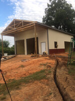
To avoid these ads, REGISTER NOW!

Clarification, Please and A New Problem on my Install

MrSurly

Well-known member
Joined
Jan 15, 2014
Messages
1,671
Location
East Texas
I'm wiring up the "Texas Budget Self Build" and I have run into some confusion AND I've run into a new problem.
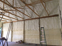
First, my specifics: 30x40x14 detached shop build; 200A service on the house (recent upgrade to support the shop build); 100A breaker in the Main panel in the house.
2AWG Cu THHN/THWN four-wire buried 20" deep, in PVC conduit for 50', new Sub Panel in the shop with 100A backfed main, 12/22 circuit box, will only use a few of them.
I will have a two-post lift (230V approx 20A). and a compressor (currently a little 3HP, planning to upgrade to 5HP). I have installed two 30A two-pole breakers 10AWG THHN in EMT. I will have three receptacle circuits and pretty minimal lighting.
At issue: I've read the myriad threads and stickied posts on sub panels and related subjects. These threads have been super-informative but have also added some fogginess to the subject in specific ways that I need clarity on. I have also talked with the inspector when I obtained the permit but I think he gave me some erroneous info. It was on the phone and I think I confused him on the build, he's not seen the site.

1.) The inspector told me that my EGC in my four wire feeder could be 10AWG. I installed it, but I'm fairly sure it needs to be 8AWG. I will replace it if need be.
2.) I've seen it stated here that the compressor must be hardwired, no plugs/receptacles allowed. If that's accurate, please tell me the criteria; is it based on application (compressor) or location (detached garage) or HP (current)? what about "portable" compressors on wheels? What about 3HP compressors?
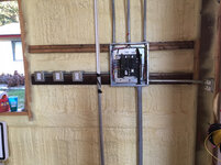
3.) I read here that type MC (12/2 Cu) is "no different than NM cable in terms of its resistance to damage"....I assume it needs to be covered up (in a wall, etc). This messes up my plan! I bought a roll of the stuff and planned to make good use of it making drops to outlets from J-boxes along a common conduit. I had mentioned this plan to the inspector and he thought it was grand, so I don't think there's a problem with being accepted...but is it a *good idea*, or should I just go ahead and pipe each outlet? There will be pics attached below. I have run 3/4 EMT in three runs and planned to use the MC and clamps to provide drops to 4sq boxes mounted on the posts. Perhaps I need to get more pipe?
3a.) If it's no better than NM and not allowed in more locations/uses, then just what the heck is MC GOOD for? I mean, why do they even MAKE it?
3b.) I was planning to use the MC to go out to canopy lighting under the porch area. Can MC be used 'outdoors'?
4. The unexpected problem that must be addressed: I am running stranded THHN (10 & 12) and I have found that I am unable to get a secure connection on the neutrals and the grounds in the provided busses.
I have twisted the wire, folded it, doubled wires under one screw... The setscrew bottoms out, the strands spread/flatten and although you can't pull the wire out, you can easily move the wire. It is NOT a solid connection. I have older GE panels that don't have this trouble. What am I missing? What is the approved fix? I'm considering tinning (soldering) the wire ends; crimping something on them... what do you guys do for this?
5.) Known issues: I'm not finished with the work of course and I have not yet installed the ground rod(s). I do know I need this. My job is sending me out of town for a while so this is a good stopping point to get y'all's input on what I've got so far and how to proceed.

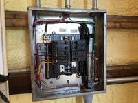
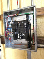
Please take a look at the pics, critique away, I want very much to know all of the details I have wrong so far.
The basis of the plan: a conduit run that crosses to the opposite corner of the shop, providing a drop for the two-post lift (red/blk 10AWG no neutral), a planned MC drop for the main lighting fixtures up into the peak area (blk 12 +neutral), two outlet circuits (red 12 +n and blue 12 +n) and then all the way to the corner for the compressor (brn&yel 10AWG no n). I'm sharing a single 12AWG EGC in this pipe. Is this OK?
There is another outlet circuit in the pipe above the panel (blue 12).
There are GFCI receptacles mounted at the panel and each outlet circuit is fed by one of these GFCIs.

While I won't skimp on wiring or safety-related things, everything else is budget directed. I'll be using things I have on hand, so the lighting will be two 4' LED shop lights over the work bench and on a 3way and two rather impressive high-bays, for now. Same with the AC: I'm going to put two 6000BTU air conditioners (120V, <6A) through the wall. Not ideal stuff, I know, but it's what I've got.

The light switch arrangement is a 3way for the bench lights; a switch for each of main lights, canopy light, entry light.
 
Last edited:
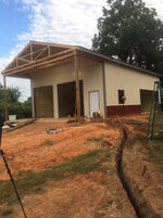
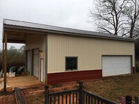
To avoid these ads, REGISTER NOW!
OP
M

MrSurly

Well-known member
Joined
Jan 15, 2014
Messages
1,671
Location
East Texas
Pics
f48f3b9565063a50efbe14efc5712f92.jpg

Found a good use for an FPE box!
4c3ee67eacd9171813fa4ad761f8cedf.jpg

1c161dcc488c827a783ea0f449441866.jpg
77afa8a26256f87148f4b530872d63f5.jpg


b8fac4a1acff4e48a44d519064ecc980.jpg
43294c8b04582d5805cba640efc23392.jpg

95c11663a59ab266bb1445b423cdbaff.jpg

aff2d5a5c2a245bf35ee30c9b69ee0a8.jpg
 

Attachments

  • 4c3ee67eacd9171813fa4ad761f8cedf.jpg
    4c3ee67eacd9171813fa4ad761f8cedf.jpg
    815.5 KB · Views: 0
  • 1c161dcc488c827a783ea0f449441866.jpg
    1c161dcc488c827a783ea0f449441866.jpg
    858.5 KB · Views: 0
  • 77afa8a26256f87148f4b530872d63f5.jpg
    77afa8a26256f87148f4b530872d63f5.jpg
    850.1 KB · Views: 0
  • b8fac4a1acff4e48a44d519064ecc980.jpg
    b8fac4a1acff4e48a44d519064ecc980.jpg
    841.7 KB · Views: 1
  • 43294c8b04582d5805cba640efc23392.jpg
    43294c8b04582d5805cba640efc23392.jpg
    921.3 KB · Views: 0
  • 95c11663a59ab266bb1445b423cdbaff.jpg
    95c11663a59ab266bb1445b423cdbaff.jpg
    917.4 KB · Views: 0
  • aff2d5a5c2a245bf35ee30c9b69ee0a8.jpg
    aff2d5a5c2a245bf35ee30c9b69ee0a8.jpg
    937 KB · Views: 0
  • f48f3b9565063a50efbe14efc5712f92.jpg
    f48f3b9565063a50efbe14efc5712f92.jpg
    896.9 KB · Views: 0
Last edited:

wyliesdiesels

Well-known member
Joined
Aug 14, 2012
Messages
20,067
Location
Modesto, CA
Woa thats a really long post with few paragraph breaks.... but here goes

I'm wiring up the "Texas Budget Self Build" and I have run into some confusion AND I've run into a new problem.
First, my specifics: 30x40x14 detached shop build; 200A service on the house (recent upgrade to support the shop build); 100A breaker in the Main panel in the house.
2AWG Cu THHN/THWN four-wire buried 20" deep, in PVC conduit for 50', new Sub Panel in the shop with 100A backfed main, 12/22 circuit box, will only use a few of them.

#2 cu was a waste of money. Only need #3... I wouldve done #2 al MHF with 90a breaker and saved quite a bit.

If the conduit is not under a residential driveway or parking area or concrete, then 20" is too shallow. Needs to be 24" to top of conduit. see table 300.5...

I dont see a retaining clip on the back fed main. Is there one?

1.) The inspector told me that my EGC in my four wire feeder could be 10AWG. I installed it, but I'm fairly sure it needs to be 8AWG. I will replace it if need be.

Inspector is wrong.

#10cu is up to 60a breaker. #8cu is for 100a see table 250.122

2.) I've seen it stated here that the compressor must be hardwired, no plugs/receptacles allowed. If that's accurate, please tell me the criteria; is it based on application (compressor) or location (detached garage) or HP (current)? what about "portable" compressors on wheels? What about 3HP compressors?

Has to do with HP ratings. You can use a receptacle IF its rated for at least the same HP as the motor. Seeing as how there are no NEMA plugs rated at 5HP (highest is 3.5HP), you would have to use expensive pin and sleeve plugs if you wanted to use an outlet.

A 3HP could go on an outlet since its 3HP.

Portable and 5HP is still the same issue.

3.) I read here that type MC (12/2 Cu) is "no different than NM cable in terms of its resistance to damage"....I assume it needs to be covered up (in a wall, etc). This messes up my plan! I bought a roll of the stuff and planned to make good use of it making drops to outlets from J-boxes along a common conduit. I had mentioned this plan to the inspector and he thought it was grand, so I don't think there's a problem with being accepted...but is it a *good idea*, or should I just go ahead and pipe each outlet? There will be pics attached below. I have run 3/4 EMT in three runs and planned to use the MC and clamps to provide drops to 4sq boxes mounted on the posts. Perhaps I need to get more pipe?

"subject to damage' is subjective and up to interpretation.

No it doesnt need to be covered up.

If youre inspector says a ok, then I would say youre good.

However, MC is hard to get straight and looks ugly compared to straight runs of EMT.

But its your shop not mine....

And whether its a good idea is something you can only answer since we dont know what type of work will be going on in there and whether the MC could be accessible to damage.


3a.) If it's no better than NM and not allowed in more locations/uses, then just what the heck is MC GOOD for? I mean, why do they even MAKE it?

MC is typically used for lighting in drop ceilings as well as in metal studs.

But it can be surface mounted just like NM...

And has many uses that arent permitted for NM wiring such as direct burial, embedded in plaster finish on brick and other masonry in dry locations only, in wet locations when listed for such(more below)...

See art 330 which is all about permitted uses for MC...

3b.) I was planning to use the MC to go out to canopy lighting under the porch area. Can MC be used 'outdoors'?

yes 330.10(A)(3) permits its use outdoors.

However, if its wet location, 330.10(A)(11) says it needs to have jacket impervious to moisture. This can be either the metal jacket being listed for that, a jacket under the metal covering or a corrosion resistant jacket over the metallic covering with conductors listed for wet locations...

4. The unexpected problem that must be addressed: I am running stranded THHN (10 & 12) and I have found that I am unable to get a secure connection on the neutrals and the grounds in the provided busses.
I have twisted the wire, folded it, doubled wires under one screw... The setscrew bottoms out, the strands spread/flatten and although you can't pull the wire out, you can easily move the wire. It is NOT a solid connection. I have older GE panels that don't have this trouble. What am I missing? What is the approved fix? I'm considering tinning (soldering) the wire ends; crimping something on them... what do you guys do for this?

What devices are you having an issue with the stranded wire? switches and outlets? bus bars?

There's a few different ways to go about this. Can do stakons if you have the right tool. Or another similar connector.

Or twist stranded ends in opposite direction.

Or leave short piece of insulation one end.

Stranded wire should have no issues under a ground or neutral bus bar lug.

One red flag is the quote in bold italic red. NEVER double up wires unless the terminal is listed for 2 wires.

5.) Known issues: I'm not finished with the work of course and I have not yet installed the ground rod(s). I do know I need this. My job is sending me out of town for a while so this is a good stopping point to get y'all's input on what I've got so far and how to proceed.

One thing i cant tell in your pics is whether the neutral bar is isolated.

Also It looks like the #10 green EGC goes to the insulated neutral bar. But i also see a ground bar on the right hand side. The EGC should be going to the ground bar NOT the neutral bar.

The GEC from the ground rods should also go to the ground bar.

The basis of the plan: a conduit run that crosses to the opposite corner of the shop, providing a drop for the two-post lift (red/blk 10AWG no neutral), a planned MC drop for the main lighting fixtures up into the peak area (blk 12 +neutral), two outlet circuits (red 12 +n and blue 12 +n) and then all the way to the corner for the compressor (brn&yel 10AWG no n). I'm sharing a single 12AWG EGC in this pipe. Is this OK?


If youre using the #12 EGC for the #10 compressor circuit then that is incorrect. Needs to be #10. But can still be shared.
 
Last edited:
OP
M

MrSurly

Well-known member
Joined
Jan 15, 2014
Messages
1,671
Location
East Texas
Woa thats a really long post with few paragraph breaks.... but here goes
Hah! True...but that's what the numbers are for!

BTW: Likely makes no difference on this discussion, but for info, the city here is on NEC 2011.... for another month. They are going straight to 2017 in September.

#2 cu was a waste of money. Only need #3... I wouldve done #2 al MHF with 90a breaker and saved quite a bit.
Good point. I could've gone with the 3cu. I'm not familiar with the mobile home wire and I still have an aversion to al but that's just me. I know the poco runs millions of miles of it... but I don't want it any closer to me than the squeeze-ups on my riser.

If the conduit is not under a residential driveway or parking area or concrete, then 20" is too shallow. Needs to be 24" to top of conduit. see table 300.5...
Interesting; I followed inspector's directive: "top of pipe at least 18 inches". Boy I would hate to have to redo that! (also notable: I asked if he needed to see the pipe in the ditch before backfill....he said NO(?))

I don't see a retaining clip on the back fed main. Is there one?
Yes, its hidden when the adjacent breakers are in place.

Inspector is wrong.
I'm.... not surprised.

#10cu is up to 60a breaker. #8cu is for 100a see table 250.122
Added to my fixit list

Has to do with HP ratings. You can use a receptacle IF its rated for at least the same HP as the motor. Seeing as how there are no NEMA plugs rated at 5HP (highest is 3.5HP), you would have to use expensive pin and sleeve plugs if you wanted to use an outlet.
A 3HP could go on an outlet since its 3HP.
Portable and 5HP is still the same issue.
Thanks for the clarification.... more questions, of course: I didn't realize the plugs had HP ratings, I only knew of current ratings. Where do 30, 40 and 50A "dryer plugs" fall in this; are they not rated for motor service? I've seen plenty of mig welders being used with dryer plugs. (I didn't say "approved")

"subject to damage' is subjective and up to interpretation.
No it doesn't need to be covered up.
If your inspector says OK, then I would say you're good.
However, MC is hard to get straight and looks ugly compared to straight runs of EMT.
But its your shop not mine....
And whether its a good idea is something you can only answer since we don't know what type of work will be going on in there and whether the MC could be accessible to damage.
I'll have to think on this while I'm away. My use of it on the lighting "drops" would have it routed on the topside of truss braces, to hide it from view. The places it would be exposed would be straight vertical drops on the surface of the timbers. I feel like I could make those straight, but I doubt they would *stay* straight.
MC is typically used for lighting in drop ceilings as well as in metal studs.
But it can be surface mounted just like NM...
See art 330 which is all about permitted uses for MC...
yes 330.10(A)(3) permits its use outdoors.
What devices are you having an issue with the stranded wire? switches and outlets? bus bars?
There's a few different ways to go about this. Can do stakons if you have the right tool. Or another similar connector.
Or twist stranded ends in opposite direction.
Or leave short piece of insulation one end.
I tried those, no joy.

Stranded wire should have no issues under a ground or neutral bus bar lug.
I agree, and yet, I am having this trouble. It's as if the screws are half a thread too short! head of the screw bottoms out, tip of the screw is not jam-tight against the bar.


One red flag is the quote in bold italic red. NEVER double up wires unless the terminal is listed for 2 wires.
Oh, I know; i just tried it to see if it would hold, and it did.

One thing I can't tell in your pics is whether the neutral bar is isolated.
Also It looks like the #10 green EGC goes to the insulated neutral bar. But i also see a ground bar on the right hand side. The EGC should be going to the ground bar NOT the neutral bar.
The GEC from the ground rods should also go to the ground bar.


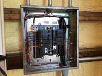
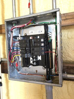
Not certain why it's built this way, but, this box has the neutral bus on the left and a spot for a bonding screw on the lug.

On the right, there is another isolated bar and lug, with another spot for a bonding screw. The two floating bars are not tied together but both of them have the facility to be bonded to the panel with a screw. The plastic baseplate of the panel actually has the two bars labeled. The bar on the left says "Neutral bus. Bond screw here ---->"
On the right, it says "ground bus. Bond screw here---->"
and as seen, there is a direct-mounted ground bus.
The bond screw IS installed in the floating ground bus. Right next to the lug.
The bond screw for the Neutral bus is NOT installed.

If you're using the #12 EGC for the #10 compressor circuit then that is incorrect. Needs to be #10. But can still be shared.
 

pattenp

Well-known member
Joined
Jun 4, 2008
Messages
10,175
Location
Virginia - USA
You are fine at 20" buried depth. NEC requires 18" of cover, unless under a driveway then it's 24". Wylie should have left out the word "Not".
 
OP
M

MrSurly

Well-known member
Joined
Jan 15, 2014
Messages
1,671
Location
East Texas
Whew! I was thinking *man!* I don't want to dig that up!!!!.
Please don't make me dig this up!


Sent from my iPhone using Tapatalk
 
OP
M

MrSurly

Well-known member
Joined
Jan 15, 2014
Messages
1,671
Location
East Texas
Another question, coach me on conduit fill, please. The main conduit run across the building to the compressor is 3/4 EMT . Current carrying conductors:
10AWG X4
12AWG X6
EGC
10AWG x1

Is this within allowable fill?


Sent from my iPhone using Tapatalk
 
Last edited:
OP
M

MrSurly

Well-known member
Joined
Jan 15, 2014
Messages
1,671
Location
East Texas
And another, I'm running the EGC to everything (even though it seems redundant in continuous EMT) but does the EGC which is bonded to the panel and will be connected to each device need to be also connected to any of the J-boxes along the run?
 
Last edited:

matt_i

Well-known member
Joined
Mar 14, 2008
Messages
10,741
Location
SE Michigan
Another question, coach me on conduit fill, please. The main conduit run across the building to the compressor is 3/4 EMT . Current carrying conductors:
10AWG X4
12AWG X6
EGC
10AWG x1

Is this within allowable fill?

Seems like you are OK, but close to the limit.

3/4 EMT can have 10pc #10awg, you have 5pc #10 and 6pc #12 plus a ground which shouldn't really carry a current unless there is trouble.
 

mm08822

Well-known member
Joined
Jan 13, 2012
Messages
6,034
Location
NJ
And another, I'm running the EGC to everything (even though it seems redundant in continuous EMT) but does the EGC which is bonded to the panel and will be connected to each device need to be also connected to any of the J-boxes along the run?

Since you chose to run an EGC in EMT, I would connect it to each metallic box throughout the entire run. In doing so, you have better assurance that the entire emt run stays grounded at all points in case the emt gets damaged and separates.

Grounding of the emt system should be independent of any installed devices.
 

W-Cummins

Well-known member
Joined
Jan 9, 2006
Messages
1,641
Location
Iowa
Another question, coach me on conduit fill, please. The main conduit run across the building to the compressor is 3/4 EMT . Current carrying conductors:
10AWG X4
12AWG X6
EGC
10AWG x1

Is this within allowable fill?


Sent from my iPhone using Tapatalk

Did not run the fill calculation, but you will need to derate the wire with what appears to be 11 current carrying conductors in the one conduit.

William.....
 

mm08822

Well-known member
Joined
Jan 13, 2012
Messages
6,034
Location
NJ
Did not run the fill calculation, but you will need to derate the wire with what appears to be 11 current carrying conductors in the one conduit.

William.....

It's at ~34% fill with the 11 conductors so no problem there. But with 10 CCC (not 11), the derating factor is 50%. So the #10's can only have 20A max load and the 12's can only have a 15A cb.

You need to eliminate 2 CCC from the conduit to drop below 10 CCC which puts you in the 70% derating factor range.
10's can now have 28A load and 12's can have 20A cb.

The 3 hp compressor motor conductors needs to be able to carry 21.25A and that works with the 8 CCC.
If you plan on upgrading to a 5HP compressor, the motor conductors need to be able to carry 35A. These conductors either need to increase to 8's (37% fill) or be in their own conduit as 10's.

Without seeing layout details, it is hard to say which is easiest option to correct with.
 

sberry

Banned
Joined
Jun 18, 2005
Messages
35,747
Location
Brethren, Michigan
I use multi wire on some of these to lower conductor count but this is a fairly small building and short runs, could run another pipe possibly to reduce fill.
 
OP
M

MrSurly

Well-known member
Joined
Jan 15, 2014
Messages
1,671
Location
East Texas
Did not run the fill calculation, but you will need to derate the wire with what appears to be 11 current carrying conductors in the one conduit.

William.....
This is why I ask my questions here. I found online fill calculators but they don't address the derating issue.
It's at ~34% fill with the 11 conductors so no problem there. But with 10 CCC (not 11), the derating factor is 50%. So the #10's can only have 20A max load and the 12's can only have a 15A cb.

You need to eliminate 2 CCC from the conduit to drop below 10 CCC which puts you in the 70% derating factor range.
10's can now have 28A load and 12's can have 20A cb.

The 3 hp compressor motor conductors needs to be able to carry 21.25A and that works with the 8 CCC.
If you plan on upgrading to a 5HP compressor, the motor conductors need to be able to carry 35A. These conductors either need to increase to 8's (37% fill) or be in their own conduit as 10's.

Without seeing layout details, it is hard to say which is easiest option to correct with.

This is good info. The conduit run is pretty straight forward about 80' total, North-West-North crossing the shop and running to the opposite corner from the panel. The fill rate drops along the run; the first drop is to the lift (two 10AWGs) then the hi-bays (two 12AWGs) the red outlet circuit drops next (two 12AWGs) and finally, the blue outlet circuit and the compressor both finish the run. I don't know if this 'stepped fill' affects the derating. The first 20' has 10CCC, then 15' with 8CCC then 10' with 6CCC and the remaining 45' or so has 4ccc. This likely doesn't change anything with the calcs but it would be no big deal to just run the lift in a new parallel pipe for that 20' or so. For that matter, I could move the hi-bay circuit into the new pipe as well. This would mean the lift pipe would have 2 10s and 2 12s. The compressor pipe would 2 10s and four 12s. Would this allow the 5HP comp without running even more pipe or 8s?
I use multi wire on some of these to lower conductor count but this is a fairly small building and short runs, could run another pipe possibly to reduce fill.
Tell me what you mean by "multi wire", please.

Thanks for the education, guys.

P.S. how does the derating calculation take into account the application of types of loads? IOW, are continuous loads (AC, Fans, Lighting) derated differently than irregular loads (compressors, power tools)?
 
Last edited:

mm08822

Well-known member
Joined
Jan 13, 2012
Messages
6,034
Location
NJ
This is why I ask my questions here. I found online fill calculators but they don't address the derating issue.


This is good info. The conduit run is pretty straight forward about 80' total, North-West-North crossing the shop and running to the opposite corner from the panel. The fill rate drops along the run; the first drop is to the lift (two 10AWGs) then the hi-bays (two 12AWGs) the red outlet circuit drops next (two 12AWGs) and finally, the blue outlet circuit and the compressor both finish the run. I don't know if this 'stepped fill' affects the derating. The first 20' has 10CCC, then 15' with 8CCC then 10' with 6CCC and the remaining 45' or so has 4ccc. This likely doesn't change anything with the calcs but it would be no big deal to just run the lift in a new parallel pipe for that 20' or so. For that matter, I could move the hi-bay circuit into the new pipe as well. This would mean the lift pipe would have 2 10s and 2 12s. The compressor pipe would 2 10s and four 12s. Would this allow the 5HP comp without running even more pipe or 8s?


P.S. how does the derating calculation take into account the application of types of loads? IOW, are continuous loads (AC, Fans, Lighting) derated differently than irregular loads (compressors, power tools)?

The ampacity derating of CCC in a conduit/raceway has no consideration for load type and are assumed loaded to their maximum for worst case scenario. Conductor count can be reduced only when loads cannot be simultaneously energized.

You are right on the edge with 6 CCC’s as these now derate to only 80%. The 2 10’s can now handle a load of 32A. The 5HP, 230vac motor has a FLC of 28A per code book and the conductors need to be rated for 125% of that – 35A. If you get a true 5HP motor and of decent efficiency, your FLA’s could be as low as 21A and the old code method of using actual motor FLA’s at 125% would put you at 26.5A. Even a motor with FLA’s of 25.6A would put you just at 32A.

IMO, I would adjust the compressor conduit fill to 6 CCC and consider it ready to handle the future 5HP motor. To be 100% up to code, it requires 8’s in the current conduit (max 9 CCC) or 10’s in a separate conduit.
 

dscheidt

Well-known member
Joined
Apr 26, 2017
Messages
2,909
Tell me what you mean by "multi wire", please.

A multi-wire branch circuit using a hot from either 'phase', with a shared neutral.

Say you have two 20A 120V circuits. That's two hots and two neutrals, for a total of four current carrying wires. If, instead, you run a multi-wire branch circuit, you will have two hots and a single neutral. It's a real neutral, so it only carries the difference between the loads on the two hots, and doesn't count as a current carrying conductor. So for your two 20A circuits, you only have two CCC, not four, and only three wires in the pipe. It's basically a 240 V circuit, so the voltage drop is lower, too. They're very widely used where conduit is in place, because they save wire and pipe fill.

Modern code cycles require that they be put on a two pole breaker, or use handle ties. That's made them less attractive, because it means a trip effects more stuff. AFCI requirements haven't help their popularity, either, but two pole AFCI are now no more expensive than 2 single pole, so they may make a comeback to some extent.
 
OP
M

MrSurly

Well-known member
Joined
Jan 15, 2014
Messages
1,671
Location
East Texas
OK, I've been busy revising, implementing all of your ideas.
1. To reduce derating due to fill, I have added a pipe. The new pipe will carry the circuit for the lift and two lighting circuits, run as a multi-wire, so the "lift pipe" has two 10AWG and two 12AWG CCCs plus a 12AWG neutral plus the 10AWG EGC.
2. The "compressor pipe" now contains two 10AWG and four 12AWG CCCs and a 10AWG EGC.
(5HP Compressor plus two separate outlet circuits)
3. The feeder conduit from the house contains two 2AWG; one 4AWG; three 12AWG (3way SW) and one 8AWG EGC.

I have separate switches for hi-bays/ West wall strips (6x4')/East wall strips (4x4')/entry light/canopy hi-bay.
Unfinished: ground rod, mounting of canopy hi-bay,
Mounting of second inside hi-bay. Installing drops to outlet boxes to be mounted on posts.
Remaining questions:
Is my comp wiring now sufficient for future 5hp duty?
I ran two separate outlet circuits (2x 12AWG hot and 2x 12AWG neutral) in the comp pipe. I thought for a moment that I could multi-wire these but since they are each req'd to be gfci, it is my understanding that there's no way to multi-wire them and maintain gfi protection. Is this correct?
The strip lights req'd outlets to install them (not built for hardwire); the outlets used (10' and 14' high) are NOT tamper proof OR gfci. Is this allowed for switched lamp circuits?

Pics as soon as I can


Sent from my iPhone using Tapatalk
 
Last edited:
To avoid these ads, REGISTER NOW!

Black Oak

Well-known member
Joined
Aug 6, 2013
Messages
161
Location
black oak arkansas
Threads like this are great. I pick up so much listening to you guys, it really is helpful. Long and specific responses that a "laymen" can grasp. Thanks to all.
 

bjcouche

Well-known member
Joined
Sep 11, 2010
Messages
509
Location
Ohio
You are correct, you cannot have a MWBC AFTER connecting to GFI outlets. To have a MWBC using GFCI outlets, you have to have the GFCI outlets located after they break out to their individual circuits. Right now you have the GFCI outlets located near your panel, if you change that to a MWBC, those GFCI outlets need to be at the other end of that conduit run.
Did I catch it that you have a couple 12 or 14awg wires run from your house to shop for the purpose of a light switch? That's a common mistake and a direct code violation. You cannot have multiple sources of power to your _detached_ building. The easiest way to get a 3 way switch installed so you can turn your shop lights on and off from your house is to install a RF remote control switch. That it's remote control and not wired between the two structures. The big box home improvement stores have them.
Brian
 

wyliesdiesels

Well-known member
Joined
Aug 14, 2012
Messages
20,067
Location
Modesto, CA
You are correct, you cannot have a MWBC AFTER connecting to GFI outlets. To have a MWBC using GFCI outlets, you have to have the GFCI outlets located after they break out to their individual circuits. Right now you have the GFCI outlets located near your panel, if you change that to a MWBC, those GFCI outlets need to be at the other end of that conduit run.
Did I catch it that you have a couple 12 or 14awg wires run from your house to shop for the purpose of a light switch? That's a common mistake and a direct code violation. You cannot have multiple sources of power to your _detached_ building. The easiest way to get a 3 way switch installed so you can turn your shop lights on and off from your house is to install a RF remote control switch. That it's remote control and not wired between the two structures. The big box home improvement stores have them.
Brian

If he puts them at the end of the conduit, then the preceding outlets will not have GFCI protection.

Also, code allows switch loops between buildings but the power must originate from the garage.
 
OP
M

MrSurly

Well-known member
Joined
Jan 15, 2014
Messages
1,671
Location
East Texas
I'd like to revisit the 3-way wiring issue. At one point I had talked with the city inspector about this plan and he said it would be no problem.
It's possibly important to note that the 3-way wiring is powered strictly from the sub panel, NOT from the house, so it's NOT 'separately derived' power. If the breaker in the house panel is off to the shop feeder, the 3-way is dead.

Also of note: I ran a 3/4 conduit in the ditch for future A/V, data,alarm; currently unused. (Should've run bigger!)
I have the option of running the 3-way in this if needed.


Sent from my iPhone using Tapatalk
 
Last edited:
mm08822

Well-known member
Joined
Jan 13, 2012
Messages
6,034
Location
NJ
OK, I've been busy revising, implementing all of your ideas.
1. To reduce derating due to fill, I have added a pipe. The new pipe will carry the circuit for the lift and two lighting circuits, run as a multi-wire, so the "lift pipe" has two 10AWG and two 12AWG CCCs plus a 12AWG neutral plus the 10AWG EGC.
2. The "compressor pipe" now contains two 10AWG and four 12AWG CCCs and a 10AWG EGC.
(5HP Compressor plus two separate outlet circuits)
3. The feeder conduit from the house contains two 2AWG; one 4AWG; three 12AWG (3way SW) and one 8AWG EGC.

I have separate switches for hi-bays/ West wall strips (6x4')/East wall strips (4x4')/entry light/canopy hi-bay.
Unfinished: ground rod, mounting of canopy hi-bay,
Mounting of second inside hi-bay. Installing drops to outlet boxes to be mounted on posts.
Remaining questions:
Is my comp wiring now sufficient for future 5hp duty?
I ran two separate outlet circuits (2x 12AWG hot and 2x 12AWG neutral) in the comp pipe. I thought for a moment that I could multi-wire these but since they are each req'd to be gfci, it is my understanding that there's no way to multi-wire them and maintain gfi protection. Is this correct?
The strip lights req'd outlets to install them (not built for hardwire); the outlets used (10' and 14' high) are NOT tamper proof OR gfci. Is this allowed for switched lamp circuits?

Pics as soon as I can


Sent from my iPhone using Tapatalk

If you run the 2 lighting circuits as mwbc's, then you need a 2 pole breaker. If 1 circuit trips it takes out the other. I would add the 2nd neutral and keep them independent with 2 single pole cb's.

The compressor wiring is still the same answer as given in post#16.

As for mwbc's on the recepts, it would really depend on the conduit path and placement of recepts - i.e. alternating cicrcuits. Most flexibility is to keep the 2 neutrals and remain independant. Also would need a 2 pole cb. Not desirable.

As for the tamper-proof and gfci ceiling outlets - for a garage and accessory buildings, you need these. For a pole barn, I would hope at 10/14' the inspector would just walk on by. You'll find out!
 

mm08822

Well-known member
Joined
Jan 13, 2012
Messages
6,034
Location
NJ
I'd like to revisit the 3-way wiring issue. At one point I had talked with the city inspector about this plan and he said it would be no problem.
It's possibly important to note that the 3-way wiring is powered strictly from the sub panel, NOT from the house, so it's NOT 'separately derived' power. If the breaker in the house panel is off to the shop feeder, the 3-way is dead.

Also of note: I ran a 3/4 conduit in the ditch for future A/V, data,alarm; currently unused. (Should've run bigger!)
I have the option of running the 3-way in this if needed.


Sent from my iPhone using Tapatalk

You are fine with this 3way plan. No need for any change.

FYI - A lot of times feeders will be in their own conduit. Fortunately, you ran #2 Cu. Technically, once you hit 4 CCC you are down to 80% ampacity. That would really stink to reduce the feeder ampacity for a few 12's. Even if the inspector caught it, you are good.
#2 Cu THHN @90C = 130A. 130A x 80% = 104A. You're good with a 100A CB.
 
OP
M

MrSurly

Well-known member
Joined
Jan 15, 2014
Messages
1,671
Location
East Texas
As for the tamper-proof and gfci ceiling outlets - for a garage and accessory buildings, you need these. For a pole barn, I would hope at 10/14' the inspector would just walk on by. You'll find out!


While I would agree he'll likely "walk on by", I am not comfortable with building it non-compliant and hoping. I just hate 'gray area' when the assumptions could get me shut down.
I want to build it right or determine IF in fact it's compliant.
Hopefully you guys can sort out my confusion on this.
In reading around the web, most mentions I see related to this are admittedly dated to 2005 and 2008. I don't know how later editions have addressed these.
My city is currently on NEC2011 (its true) and they are adopting NEC2017 in Sept.
I am working to the 2011 due to my existing permit even if I don't finish until later.

At question are the duplex receptacles that are installed at ceiling height (10' & 14').
These receptacles are
1.) dedicated to the strip lighting
2.) "inaccessible" without ladders
3.) switched for lighting control
4.) necessary because the strips aren't built for direct wiring.

Is it true that these receptacles are excepted from TP and GFCI due to either #1 OR #2?


Sent from my iPhone using Tapatalk
 

mm08822

Well-known member
Joined
Jan 13, 2012
Messages
6,034
Location
NJ
My city is currently on NEC2011 (its true) and they are adopting NEC2017 in Sept.
I am working to the 2011 due to my existing permit even if I don't finish until later.

At question are the duplex receptacles that are installed at ceiling height (10' & 14').
These receptacles are
1.) dedicated to the strip lighting
2.) "inaccessible" without ladders
3.) switched for lighting control
4.) necessary because the strips aren't built for direct wiring.

Is it true that these receptacles are excepted from TP and GFCI due to either #1 OR #2?


Sent from my iPhone using Tapatalk

from 2011 nec:
The hardline answer is you need gfci protection for all 15/20a 120 vac recepts.
The tamper-resistant is not required above 5.5 ft.

Call the AHJ and get his "interpretation". His opinion will determine the color of this sticker you get.
 
OP
M

MrSurly

Well-known member
Joined
Jan 15, 2014
Messages
1,671
Location
East Texas
Incorporated all of the advice given above; I have also added more circuits as time has passed. Being gone for months certainly dampens the progress around here! Anyway, thanks to all of you, Even with the changes I have made during this build, beginning in June '17 and completing Feb '18, today the city inspector blessed the building structural AND the electrical! I am now *done* with approvals. Now I have NO MORE excuses! I need to get to work doing actual IN shop stuff, now!
bcfd0563929ff1dd5c98bc0a3954cb52.jpg
c0f19db5b0480af9b89d8893a8729bdc.jpg
dbe7a3060e5ddf6ed013408ba8af0a3d.jpg
474d814ba6cdbf725c3f51d5dabab554.jpg
 

Attachments

  • 474d814ba6cdbf725c3f51d5dabab554.jpg
    474d814ba6cdbf725c3f51d5dabab554.jpg
    855.1 KB · Views: 0
  • dbe7a3060e5ddf6ed013408ba8af0a3d.jpg
    dbe7a3060e5ddf6ed013408ba8af0a3d.jpg
    670.6 KB · Views: 0
  • c0f19db5b0480af9b89d8893a8729bdc.jpg
    c0f19db5b0480af9b89d8893a8729bdc.jpg
    825.7 KB · Views: 0
  • bcfd0563929ff1dd5c98bc0a3954cb52.jpg
    bcfd0563929ff1dd5c98bc0a3954cb52.jpg
    932.1 KB · Views: 0
Last edited:

wyliesdiesels

Well-known member
Joined
Aug 14, 2012
Messages
20,067
Location
Modesto, CA
Incorporated all of the advice given above; I have also added more circuits as time has passed. Being gone for months certainly dampens the progress around here! Anyway, thanks to all of you, Even with the changes I have made during this build, beginning in June '17 and completing Feb '18, today the city inspector blessed the building structural AND the electrical! I am now *done* with approvals. Now I have NO MORE excuses! I need to get to work doing actual IN shop stuff, now!
bcfd0563929ff1dd5c98bc0a3954cb52.jpg

Im not gonna read through all the comments.

Is that a main service panel or a subpanel?

If subpanel, is the right hand bar that is next to the breakers, bonded to the enclosure and not connected to the left hand neutral bar? Usually there is a strap that connects the left and right bars....
 

Attachments

  • bcfd0563929ff1dd5c98bc0a3954cb52.jpg
    bcfd0563929ff1dd5c98bc0a3954cb52.jpg
    160.1 KB · Views: 0
Last edited:
OP
M

MrSurly

Well-known member
Joined
Jan 15, 2014
Messages
1,671
Location
East Texas
Im not gonna read through all the comments.

Is that a main service panel or a subpanel?

It is a sub panel

If subpanel, is the right hand bar that is next to the breakers, bonded to the enclosure and not connected to the left hand neutral bar? Usually there is a strap that connects the left and right bars....


Actually, this is me quoting myself from the previous discussion:

Not certain why it's built this way, but this box has TWO Floating bus bars, the neutral bus on the left with a spot for a bonding screw at the wire lug.

On the right, there is ANOTHER isolated bar and lug, with another spot for a bonding screw. The two floating bars are not tied together but both of them have the facility to be bonded to the panel with a screw. The plastic baseplate of the panel actually has the two bars labeled. The bar on the left says "Neutral bus. Bond screw here ---->"
On the right, it says "ground bus. Bond screw here---->"
and as seen, there is a separate chassis-mounted ground bus.
The bond screw IS installed in the floating ground bus. Right next to the lug.
The bond screw for the Neutral bus is NOT installed.
 

Bert_

Well-known member
Joined
Dec 24, 2016
Messages
9,771
Location
NW Iowa
Those ge tlm1212's are kind of goofy with those ground and neutral bars. Any reason why you went with that panel as opposed to a full sized 20 space with a factory installed main? Then you would have room for full size breakers instead of the thqp's

I can't imagine this was any cheaper by the time you bought a separate 100a breaker to install as the main.
 

wyliesdiesels

Well-known member
Joined
Aug 14, 2012
Messages
20,067
Location
Modesto, CA
Those ge tlm1212's are kind of goofy with those ground and neutral bars. Any reason why you went with that panel as opposed to a full sized 20 space with a factory installed main? Then you would have room for full size breakers instead of the thqp's

I can't imagine this was any cheaper by the time you bought a separate 100a breaker to install as the main.

yeah i hate those 1/2" breakers. They never have a snug fit feeling the panel and always sag making installation of the deadfront a PITA....
 

Norcal

Well-known member
Joined
Mar 16, 2008
Messages
13,769
yeah i hate those 1/2" breakers. They never have a snug fit feeling the panel and always sag making installation of the deadfront a PITA....

Not a good sign in a new installation to have a panel full of twins.
 
OP
M

MrSurly

Well-known member
Joined
Jan 15, 2014
Messages
1,671
Location
East Texas
Those ge tlm1212's are kind of goofy with those ground and neutral bars. Any reason why you went with that panel as opposed to a full sized 20 space with a factory installed main? Then you would have room for full size breakers instead of the thqp's

I can't imagine this was any cheaper by the time you bought a separate 100a breaker to install as the main.


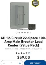
Actually, @ Lowes, 59bux includes the 100A main.
The cheap price along with the fact that I have the 20 space you referred to, inside the house with quite s few thqps in place.
Are the thqps undesirable?
Is it one of those things that people “in the know” would never use?Obviously they’re listed, etc and probably a few billion of them in use.
What’s their downside?
Originally I was planning on gas heat, but that changed and now two electric heaters now take up four poles, but it’s not out of space, yet. The thqps do ‘save’ space.
I mean *seriously* is there a possible SAFETY issue with these breakers?
If that’s the case, I’m not ruling out swapping out the panel(s) to larger capacity.
d51ef0b9fcff95ca9d85f4ff135548cc.jpg


Sent from my iPhone using Tapatalk
 

Attachments

  • d51ef0b9fcff95ca9d85f4ff135548cc.jpg
    d51ef0b9fcff95ca9d85f4ff135548cc.jpg
    270.3 KB · Views: 0
Last edited:

Bert_

Well-known member
Joined
Dec 24, 2016
Messages
9,771
Location
NW Iowa
Don't get me wrong the thqp's are OK, I just like to reserve their use for existing panels where I run out of space. For a new install I like to have enough spaces for full sized breakers.

The real downfall of those breakers is with heavy or continuous loads. The thqp's have smaller contacts and less area to get rid of heat, loaded breakers will run warm, a smaller case makes it worse.

I guess I've never seen a 12 space that came with a main, either way the TM2010 is around 65.00... The THQL's are a buck or two cheaper than THQP's also.
 
OP
M

MrSurly

Well-known member
Joined
Jan 15, 2014
Messages
1,671
Location
East Texas
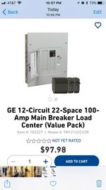
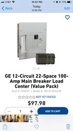
A weird thing I just noticed; I pulled up my online record of Lowes buys and learned that the record shows that I paid for this unit
eae2391b28673f8113218b9ba072d9eb.jpg

However, the box I actually left with was this one
30196ed938109ad45413636a743a39dc.jpg.so, yeah I wouldn’t have paid 97 for it(!)
Apparently, I *stole* it.


Sent from my iPhone using Tapatalk
 

Attachments

  • eae2391b28673f8113218b9ba072d9eb.jpg
    eae2391b28673f8113218b9ba072d9eb.jpg
    129.2 KB · Views: 0
  • 30196ed938109ad45413636a743a39dc.jpg
    30196ed938109ad45413636a743a39dc.jpg
    125.2 KB · Views: 0
To avoid these ads, REGISTER NOW!
Top Bottom