To avoid these ads, REGISTER NOW!

Help straightening/fixing bent tractor steering centerlink (pipe)

Pressingonward

Well-known member
Joined
Mar 9, 2016
Messages
522
Location
SW WA
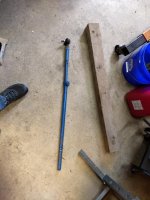
Hi everyone, I've got a 70's Ford 1000 tractor that recently suffered a bit of a mishap - the left front axle knee broke (cast iron, looks like it's been cracked for quite a while before it broke), and in the process of the wheel falling off, it bent the steering centerlink that connects the left and right spindles to each other.

I was able to find a good used knee axle, and what I thought was the correct centerlink. Tonight I discovered that the new centerlink is definitely not going to work - it uses RH threads on the tie rod end and mine uses LH threads. I'm sure I could track down the right rod end eventually, but I'd like to get my tractor back up and running ASAP, preferably tomorrow...

So that leads to my question - what's the best way to fix this thing?

attachment.php


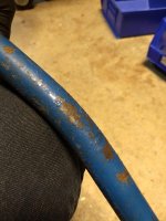
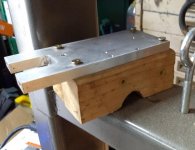
The pipe measures 27.5mm, or just under 1 1/8" OD. I can't measure the ID, but it is thin-walled. I don't know if it is iron or steel. One end is welded to an obviously cast piece, but again I don't know whether it is cast iron or cast steel:

attachment.php


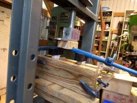
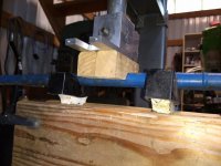
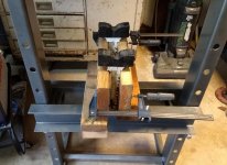
I don't have a pipe bender, but I do have a press and lots of junk to fabricate fixtures out of. The pipe is already slightly deformed at the bend, which makes me worried I'll flatten it further if I try to bend it straight again. My other thought is to cut out the bent section and weld in a replacement piece. I'm comfortable doing this as long as it's steel pipe...

What do you guys suggest? Here's a closeup of the bend:

attachment.php
 

Attachments

  • IMG_20200516_200334144_crop_28.jpg
    IMG_20200516_200334144_crop_28.jpg
    148.4 KB · Views: 735
  • IMG_20200516_200415924.jpg
    IMG_20200516_200415924.jpg
    56.8 KB · Views: 411
  • IMG_20200516_200358915.jpg
    IMG_20200516_200358915.jpg
    82.2 KB · Views: 408
To avoid these ads, REGISTER NOW!

garfunkle24

Well-known member
Joined
Mar 18, 2008
Messages
3,429
Location
Saskatoon, Canada
For stuff like that, after straightening I like to find piece of pipe with an ID close to the OD of the shaft and weld it on over that section. Between the deformation and work hardening etc that section will never be strong enough again without reinforcement.

As an ag and heavy duty tech of 20+ years, I would guess it is all steel.

Also, you could cap and pack with sand to reduce deformation when straightening.
 

gorilla

Well-known member
Joined
Dec 13, 2007
Messages
1,653
Press it straight and weld some angle iron over it for reinforcement. The welds tell you it's steel.
 

C_F

ALLIANCE MEMBER
Joined
Jan 21, 2005
Messages
9,675
Location
Utah...SNOW BLOWS!
Press it straight.
If you don't have a press, bolt it back on, then use a 2x4 against a tree & ram that thing straight, ramming the tractor against the 2x4 until it's mostly straight. :thumbup:

I seriously doubt it's cast iron, regardless.
 

gte718p

Well-known member
Joined
Mar 12, 2009
Messages
3,977
For stuff like that, after straightening I like to find piece of pipe with an ID close to the OD of the shaft and weld it on over that section. Between the deformation and work hardening etc that section will never be strong enough again without reinforcement.

As an ag and heavy duty tech of 20+ years, I would guess it is all steel.

Also, you could cap and pack with sand to reduce deformation when straightening.


I'm with Garfunkle though I would go a step further. Find a pipe it an it to match OD of steering arm, us a press and some heat to arm straight, sleeve the entire thing, use some weld at the end and maybe a few plug welds. Stronger then ever.

Of course it was made by welding a pipe to the coupler. You could always just cut at the old weld and weld a new piece of tubing in. That would not be inappropriate.
 

welder4956

Well-known member
Joined
Apr 8, 2010
Messages
3,072
Location
Birmingham, AL USA
From the O.D. dimension, it sounds like it is made from 3/4" steel pipe. Nominal O.D. for 3/4" pipe is 1.050" (26.67 mm) and with the manufacturing tolerance could easily have a measured O.D. of 27.5 mm. You will have to measure the wall thickness of the existing link to match it to the right pipe schedule or go heavier if it will fit. Schedule 40 pipe has a nominal wall thickness of 0.113" (+/- 12.5%) and Schedule 80 has a nominal wall thickness of 0.154" (+/- 12.5%). The end link should slide up inside the pipe, so grind the old weld off to the O.D. of the link to avoid damaging the link. Weld the new pipe on and be done with it.

Edit: Looks like there is a nut welded to the other end for the threaded portion of the tie rod end. You will need to cut that nut off and re-use it or find a new nut to replace it. Bevel the end of the pipe to get good penetration, but don't melt through to the inside or it may interfere with the threads on the end link.

attachment.php
 
Last edited:
OP
P

Pressingonward

Well-known member
Joined
Mar 9, 2016
Messages
522
Location
SW WA
Thanks for the feedback guys. I figured it was steel, but didn't want to assume...

It's a metric tractor (made in Japan by Shibaura for Ford), so the pipe probably really is metric.

I'll have a go at straightening the link, and if it goes badly I'll find a replacement piece of pipe. I can use the lathe at work to adjust the ID at the ends as necessary.

I do like the idea of bracing the existing pipe if I can straighten it - certainly don't want it to fold unexpectedly under load...
 

metlmunchr

Well-known member
Joined
Sep 10, 2011
Messages
1,278
FWIW, the clamp piece that the tube is welded to is a forging rather than a casting. You can identify this by the width of the parting line. If the part was cast, the parting line would be much more narrow, in the range of 1/16" or slightly more.

If the tube kinks as you try to straighten it, you can cut the weld at the forging and weld in a new tube. The forging likely has a tail section that's slid into the tube so that weld isn't a **** joint, so you wouldn't want to just saw the pieces apart at the weld but rather cut thru the tube adjacent to the weld and slide the two pieces apart.
 

joe49

Well-known member
Joined
Sep 25, 2009
Messages
1,883
Location
Tonica, Il
If you have a oxy/ac torch, heat to cherry red with you and it in a shaded place, 1/2 the circumference on the outside of the bend do this in a narrow heat no more than 1/2'' wide, pull to straighten with one end in a vice or some way restrained. Work from one end use a straight edge to gauge progress. Don't rush it, don't go gorilla on it or try bigger heats, take your time. If you go slow and easy you can bring it to a ''can't tell''.
 

matt_i

Well-known member
Joined
Mar 14, 2008
Messages
10,728
Location
SE Michigan
I like to use 3 homemade angle blocks (angle iron & square tube) and a large C-clamp on a thick workbench, but it can be done on something considerably more rigid like an I-beam.

That one would take the assistance of the "blue wrench" to do correctly in my opinion.
 
To avoid these ads, REGISTER NOW!

garfunkle24

Well-known member
Joined
Mar 18, 2008
Messages
3,429
Location
Saskatoon, Canada
The forging likely has a tail section that's slid into the tube so that weld isn't a **** joint, so you wouldn't want to just saw the pieces apart at the weld but rather cut thru the tube adjacent to the weld and slide the two pieces apart.

Great point. The reason I was loathe to suggest just cutting it out and welding in new tube was that without knowing the welding experience of the OP, it's a lot harder to get a good strong **** weld on tubing than to just reinforce the existing tube.

As you point out, it might not be a **** weld if the forging DOES have a tail.

I would consider a steering link to be a critical part in regards to safety, so I just felt that straightening and reinforcing was less dependent on the OP's welding experience than welding in new tubing.
 

joecon

Well-known member
Joined
Oct 4, 2010
Messages
681
I would look at your used part again, the one you said has left hand threads. It should have left hand threads on one side and right hand threads on the other side. It is like a turn buckle when you turn the center the ends move in and out depending on which way you turn it.
 

sberry

Banned
Joined
Jun 18, 2005
Messages
35,747
Location
Brethren, Michigan
Work at it, bend back and see how it goes before getting carried away with every scheme. If I wanted to use it would have been straightened and back on. Bet I could straighten it with a hammer a little bigger than a 4# in a few minutes and you would have to look hard to tell.
 
Last edited:

Monza Harry

Well-known member
Joined
Dec 29, 2018
Messages
1,433
Location
Windsor ON
FWIW, the clamp piece that the tube is welded to is a forging rather than a casting. You can identify this by the width of the parting line. If the part was cast, the parting line would be much more narrow, in the range of 1/16" or slightly more.

If the tube kinks as you try to straighten it, you can cut the weld at the forging and weld in a new tube. The forging likely has a tail section that's slid into the tube so that weld isn't a **** joint, so you wouldn't want to just saw the pieces apart at the weld but rather cut thru the tube adjacent to the weld and slide the two pieces apart.

I like to use 3 homemade angle blocks (angle iron & square tube) and a large C-clamp on a thick workbench, but it can be done on something considerably more rigid like an I-beam.

That one would take the assistance of the "blue wrench" to do correctly in my opinion.

I would look at your used part again, the one you said has left hand threads. It should have left hand threads on one side and right hand threads on the other side. It is like a turn buckle when you turn the center the ends move in and out depending on which way you turn it.

Work at it, bend back and see how it goes before getting carried away with every scheme. If I wanted to use it would have been straightened and back on. Bet I could straighten it with a hammer a little bigger than a 4# in a few minutes and you would have to look hard to tell.
I agree here that would be a forging and should have a tail, and this should have a RH/LH thread arrangement that nut should also have a "Register" or tail in the tube. The other suggestions will easily carry you until you can do an in depth repair. I love me some BFH action, watch the pinkies black and blue are good colour combo's for cars, tools, etc. fingers not so much, don't ask how I know! :lol_hitti The suggestion to use 3/4" Black Pipe is a No-No black pipe [or any conduit/fence pipe etc.] isn't tough enough for anything structural, use "Erew" [welded seam] at a minimum, DOM would be considered SOP for most safety critical parts. For the speed of most farm tractors EREW would most likely be fine and on the shelf at most steel houses in a size you could bore out to fit [1.250" Dia.X 0.187 wall. will have an inside Dia. of ~0.875" but will not be round with a seam also. Hope this helps. Harry
 
Last edited:
OP
P

Pressingonward

Well-known member
Joined
Mar 9, 2016
Messages
522
Location
SW WA
Thanks to everyone for the input - this job is done!

Here is what I did, and I'll address a few of the comments and alternative suggestions at the end:

I started by figuring out how to fixture this thing in my press. My original thought was to make wooden "U" blocks to support the pipe in 3 places and help it hold the right shape while pressing. I took a scrap of 2x4 about 5" long and drilled a 1" hole through it with a holesaw - 1" is the closest thing I had to 27mm, which is the OD of the pipe. I then took a half-round file and increased the hole size a bit before deciding I had better split the block before going all the way out to 27mm.

I cut the block through the center of the hole using my vertical bandsaw (always nice to have an excuse to use it :bounce:
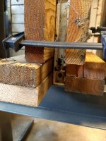
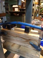
), then stacked the two halves next to each other and screwed them together to make a block that is 3" wide. I finished cleaning up the "U" with a round file, out to 26.5mm - I figured the softwood would crush the extra half millimeter and better support the tube than if I went for a perfect line fit right out of the gate - plus I was tired of filing :spit:

Finally, I screwed a scrap of aluminum (that happened to have 3 out of the four screw holes I needed already) to the back of the block to distribute the press force better. Sorry for no in-process pics, but here is what the final block looks like:

attachment.php


After spending about 30+ minutes making the one block, I decided to look for another solution for the other two supports. A few minutes surveying my miscellaneous piles of **** yielded fruit - my 3 ton jackstands with Horror Freight rubber pads on top had almost exactly the right profile to support the pipe - if I could figure out how to fixture them onto the press.

I was very happy that the solution ended up being quick and easy. The press table was just wide enough that I could set the jackstand inserts against the top of it and just use some wood scraps to hold them upright, with a couple clamps to keep everything in place:

attachment.php


attachment.php


A little sketchy looking, but it worked great. Put the steering linkage into the press and got to it:

attachment.php
 

Attachments

  • IMG_20200517_111601036.jpg
    IMG_20200517_111601036.jpg
    104.8 KB · Views: 194
  • IMG_20200517_111023263.jpg
    IMG_20200517_111023263.jpg
    149.3 KB · Views: 193
  • IMG_20200517_111033697.jpg
    IMG_20200517_111033697.jpg
    118.8 KB · Views: 192
  • IMG_20200517_111551638.jpg
    IMG_20200517_111551638.jpg
    99.4 KB · Views: 189
OP
P

Pressingonward

Well-known member
Joined
Mar 9, 2016
Messages
522
Location
SW WA
attachment.php


Here is the press all set up and ready to start

attachment.php


And the pipe looking perfectly straight - it was quick and easy!

Unfortunately I got a little greedy - the pipe was almost perfect after the first press, but I decided to go for total perfection and get the last little wave out of it - no pics, but I did more harm than good (slightly) and had to press it a third time to get to the end result, which was essentially the same as after the first press. Who was it that said that "perfection is the enemy of good enough?" How right they were!

Anyways, it turned out really good:

attachment.php


There is a slight bend at the end with the forged piece still - it almost looks like the forged piece was welded on crooked, but it could just be bent slightly. Either way, I didn't want to touch this area and risk cracking it near the weld. It bends by about 5/16" (8mm) over the length (looks worse in the picture than it actually is), which is plenty close for a tractor!

Now to address some of the comments and suggestions, which I definitely appreciated:

I elected NOT to weld on any reinforcement or slide another pipe over the top. I thought long and hard about this, but chose not to since the pipe straightened out very easily and maintained a nice round cross section - if it had stayed ovalized or developed a flat spot I would have reinforced it. Considering how easily this bent back into shape with very little springback I think it's a mild ductile steel that's at low risk of work hardening and cracking unexpectedly. If anyone thinks I'm out in left field here please let me know :thumbup:

I didn't use a torch because I don't have a working torch - I've got an empty oxygen tank and a propane torch setup that someone gave me, plus some acetylene torch bits and pieces. I desperately need to go through it all and come up with a working setup, since I could use it frequently. Probably sell off the propane torch parts and go with oxy/acetylene which should be far more versatile.

One of you questioned my welding ability for replacing the tube outright - how dare you! Just kidding :lol_hitti - I think this was an excellent point to bring up. I used to be a decent mig welder, but I didn't have one for a period of about 5 years, and the little Hobart Handler 140 I picked up last year has sadly only been used twice. In other words, I'm very rusty and would need to practice before trusting myself to do a structurally critical weld.

Monza Harry brought up the "speed of most tractors" - I'll respond to this because I find it hilarious. This little tractor has 9 forward gears (1,2,3 in L, M, and H) plus 3 reverse. I've never taken it on a full speed run (I hear you gotta go to the salt flats to do such a thing :p), but per the manual it'll hit a top speed of 8.7 mph! Hmm, wonder what would happen if I put a Delorean badge on it and revved it out to 8.8? :lol_hitti

Anyways, thanks everyone for all of your help! I got it all together and put it back to work :)
 

Attachments

  • IMG_20200517_111933902.jpg
    IMG_20200517_111933902.jpg
    153.6 KB · Views: 188
  • IMG_20200517_112140198.jpg
    IMG_20200517_112140198.jpg
    131.1 KB · Views: 187
  • IMG_20200517_113605352.jpg
    IMG_20200517_113605352.jpg
    107.2 KB · Views: 188

Monza Harry

Well-known member
Joined
Dec 29, 2018
Messages
1,433
Location
Windsor ON
Monza Harry brought up the "speed of most tractors" - I'll respond to this because I find it hilarious. This little tractor has 9 forward gears (1,2,3 in L, M, and H) plus 3 reverse. I've never taken it on a full speed run (I hear you gotta go to the salt flats to do such a thing :p), but per the manual it'll hit a top speed of 8.7 mph! Hmm, wonder what would happen if I put a Delorean badge on it and revved it out to 8.8? :lol_hitti

Anyways, thanks everyone for all of your help! I got it all together and put it back to work :)
My Dad used to have a JD "LI" with 3rd being a road gear being a former Ministry of Transportation tractor with a sickle bar for ditches it would go ~15 MPH plenty fast enough for a 1938 tractor with no suspension I can attest, probably the reason for the non OEM hood too I suspect. I have to say I love the ingenuity of the jack stand Vee blocks! :thumbup: Harry
 

gearhead1

Well-known member
Joined
Oct 14, 2013
Messages
1,935
Location
NC
I’ve pulled the drawbar/ball out and used the hitch receiver on my truck to straighten stuff before.

Most steel like that is going to be kinda ductile. They typically aren’t going to have something exotic in an application like that. I ran a 1980 Dodge Challenger, the 4cyl one made by Mitsubishi, on a dirt track. We’d get hit or hit something and the center link or strut rods would bend. We’d bend them back and be fine until it got hit again. It would have probably lasted the life of the vehicle on the street.

Good work. Million ways to do it. You got there and that’s what matters.
 

Bretny

Well-known member
Joined
Jul 31, 2017
Messages
3,918
Location
Dutchess county NY
Looks almost perfectly straight for a tractor that prob does 20mph max. I wouldnt bother with trying to make it stronger. It alreaty survived the wheel falling off. What do you want the steering box to crack or front axle to fall out next time a knuckle breaks?
 

matt_i

Well-known member
Joined
Mar 14, 2008
Messages
10,728
Location
SE Michigan
Great job and nice way to cobble your setup to make it work :thumbup:

Wood is an excellent low cost material for so many things!
 
To avoid these ads, REGISTER NOW!
Top Bottom