To avoid these ads, REGISTER NOW!

Tappet Wrenches Only: History, Use, and Examples!

Private Lugnutz

Well-known member
Joined
Mar 30, 2012
Messages
30,572
Location
The Authentic Jersey Shore
INTRO POST 1 of 4

Intro 1.jpg

The subject of tappet wrenches comes up frequently on GJ, including brand-specific threads (e.g., most recently in the “Craftsman Long C” thread), the “Show us your DOE wrenches” thread, and plenty of Whatzit? threads.

They tend to generate lots of questions. Such as, why were they so thin? (Because the tappet/lifter and adjusting screws were thin and close together.) Why were they so long? (Reach and and avoidance.) Why did they come in pairs? (Because tappet/lifter and adjusting screws did.) Then why did some not come in pairs? (That is a good question.) What was that oddball 17/32” size for? (A few automobiles and a whole bunch of trucks.) How were they used? (Not unlike chopsticks!)

They also tend to start arguments. Engine stopped, TDC, and cold? Or warm and idling? Cussworthy or easy? Feeler gauge or no feeler gauge? Is it really, as the old saying goes, “better to hear them than smell them?” (It all depends – but that is NOT the subject of this thread!)

The discussions are many, brief, scattered, and not easy to find in a search, and because it tends to threaten a side-track or a deep dive, people usually move on with the main thrust of the thread. Consequently, some questions never get properly or fully answered, and the subject has not been centrally addressed in one place.

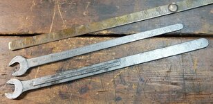
As a collecting category, though, they are actually complex wrenches to understand, made in several disparate styles (SOE, DOE with 15* and 15* angles, DOE with 15* and 22-1/2* angles) and configurations (same sizes on each end, different sizes on each end, same OAL, graduated OAL’s, etc), sometimes by the same manufacturer, with only their long thin beam and jaws in common, and worthy of their own dedicated space.

Hence, this thread.

(I’m not going to lie. I am fond of collecting them, and my ulterior, not-so-secret motive might be to have a place that becomes Tappet Trade Central for those with the same predilection.)
 
Last edited:
To avoid these ads, REGISTER NOW!
OP
P

Private Lugnutz

Well-known member
Joined
Mar 30, 2012
Messages
30,572
Location
The Authentic Jersey Shore
INTRO POST 2 of 4

Most of us are generally familiar with the evolution of overhead valves and ubiquitous tools combining some type of end wrench and some kind of screwdriver blade to make the adjustments of tappet/lifter, plunger, pushrod valve clearance (converting rotational energy into optimal vertical power without a rattle, if too loose, or a burned valve or worse, if too tight) easier…

Intro 2.jpgIntro 3.jpgIntro 4.jpg

…and much later, the gradual decline and/or changes in the overall need and simplified methods for making the adjustments at all.

This is NOT a thread for those tools!

It’s only when we look back to side-valves and the zenith of the T and L Flathead era, up through WWII really, the heart of vintage tool collecting, that we begin to realize how tricky the procedure could be, testing manual dexterity and patience with at least two and sometimes three wrenches simultaneously, and how interesting the wrenches are.

Here are most of my keepers, pouched sets, sets in need of pouches, and partial sets I am still building onesy-twosy as I find them.

Intro 5.jpg
 
OP
P

Private Lugnutz

Well-known member
Joined
Mar 30, 2012
Messages
30,572
Location
The Authentic Jersey Shore
INTRO POST 3 of 4

Before I delve into my collection, I am going to start with some very interesting and extremely helpful charts for some much needed context.

These are composites that I made by combining excerpts from page 22 and 23 of the Bonney catalog No. 33 (1933). The wrench numbers (e.g., 420, 424, etc) you see next to each passenger car and truck are Bonney tappet wrench numbers, but with the key that I have placed to the right providing a correlation of the Bonney part numbers to milled opening sizes, the chart can be used for any tappet wrenches, regardless of brand. The chart essentially tells us how many wrenches were needed to adjust valve tappet clearance and what sizes they were for all the cars and trucks that are listed.

Intro 6 - 1933 Bonney Cat Tappet Excerpt Composite - Cars.jpgIntro 7 - 1933 Bonney Cat Tappet Excerpt Composite - Trucks 1.jpgIntro 8 - 1933 Bonney Cat Tappet Excerpt Composite - Trucks 2.jpgIntro 9 - 1933 Bonney Cat Tappet Excerpt Composite - Trucks 3.jpg

As you can see, despite many GJ’ers either outright denying it or doubting it, it was obviously a matter of fact (in the 1930’s, anyway!) that many engines required three (3) tappet wrenches. In fact, there are way more cars and trucks with engines requiring three (3) tappet wrenches than there are cars and trucks with engines requiring only two (2) wrenches.
 
OP
P

Private Lugnutz

Well-known member
Joined
Mar 30, 2012
Messages
30,572
Location
The Authentic Jersey Shore
INTRO POST 4 of 4

Most guys have experience or knowledge of needing two tappet wrenches, one for the nut at the top of the tappet or lifter itself and one for the adjusting screw on top of that. In fact, my only hands-on personal experience with tappet wrenches is setting the valve clearance on my 1943 Willys MB, and it takes two. It’s done at TDC for ignition, when both valves are closed. The tappet in the L head is not on a cam lobe, and the valve is held closed by a spring. The tappets are self-locking. (Only early jeeps had separate locknuts.) You hold a tappet wrench with a 1/2” opening to hold the lifter/tappet (hex nut), and another with the same size opening to turn the hex head on the adjuster screw. The TM says you do it with the same hand, a feeler gauge in the other. The tappets and stems were worn/ground bad on mine, so a feeler wasn’t much use, and I followed an equation-turn method (based on the spec that an L134 engine tappet adjuster screw has 24 threads per inch, and that 1 complete 360* turn of the tappet adjuster hex head was 0.042“) that is well-known in the G503 community. To be honest, it always took a lot of trial and error to get it right.

Here’s an L134 engine. (Ignore the valve keepers, which are unusual in a wartime block, and before someone says it, yes, I know the springs are upside down! Don’t ask!)

Intro 10.jpg

Here’s an illustration of an L134 engine from a jeep TM showing two tappet wrenches in use. The wrench in his left hand is holding the tappet still. The left in his right hand is making the adjustment.

Intro 11.png
Here’s an illustration from a different manual showing two tappet wrenches and a feeler gauge in use. This is the famous "scissors" method. The left hand is holding the feeler gauge. The fingers of the right hand are holding the wrench at the bottom on the tappet while the thumb gently nudges the adjusting screw.

Intro 12.jpg

But, here is an illustration I grabbed from a period book showing three (3) wrenches in use (made by Bonney, by the way!),
and an illustration from a modern book on antique car maintenance, showing why.

Intro 14.jpg

Intro 15.jpg

It seems as though the third wrench in these three-wrench set-ups is for a valve-tappet type in which the locknut is different, separate from, not a part of the hex head on a self-locking tappet/lifter. My impression is that you needed to hold the tappet/lifter itself steady or still, or it would turn, loosen the locknut, and then turn the adjuster, and when you're done setting your lash, tighten the locknut, while holding the tappet/lifter, because all three were independent of each other.

In both figures one hand is using two wrenches to hold the tappet and loosen the locknut, while the other hand is using a wrench to make the adjustment.

Having said all that about 2- and 3-wrench tappet adjustments, I have no clue how you would adjust valve tappet clearance with only one (1) wrench. There are several cars and trucks like that. Not only no jam nut, but no need to hold the tappet?

For those who are curious, you should be able to use the chart above, identify a car or truck by make, model, and engine type that needed three (3) wrenches, or one (1) wrench, and then go find some views or maintenance procedures for those vehicles to see if it provides an explanation. I will probably do that in good time, but if someone beats me to it, I won’t be upset.

Or, someone smarter than I, with more experience working on more vintage engines (such as Provincial, humber or ttpete, etc), might know the answer.
 
Last edited:
OP
P

Private Lugnutz

Well-known member
Joined
Mar 30, 2012
Messages
30,572
Location
The Authentic Jersey Shore
I will eventually post more of my collection.

Please post any information you have on the subject - and especially please post your examples! I know there are a lot of nice pouched and boxed sets and a lot of nice loose partial sets and orphans floating around GJ.

Anecdotes that are on subject are always welcome too! :thumbup:
 

leg17

Well-known member
Joined
Aug 11, 2011
Messages
1,373
Location
Kentucky
TAPPET WRENCHES ALLOY STEEL

Alloy Artifacts comments that Herbrand, like many other wrench makers, first introduced various alloy steels, often some combination of chrome, vanadium, and other elements. The need for a stronger steel became readily apparent in the necessarily thin tappet wrenches.

AA notes that Herbrand advertised a 1919 introduction of their alloy steel, while the earliest examples shown, and referenced in print, dated around 1923.

AA has determined that the script HERBRAND logo was first used in 1921. That is shown in the AA example.

The attached photos show one such wrench, with script logo, and two earlier examples, with simple block lettering in a raised panel. These examples apparently pre-date the script logo, and can be assumed to be from 1919-1921 manufacture. This can verify the 1919 claim in the period Herbrand literature.
 

Attachments

  • P1020506.JPG
    P1020506.JPG
    163.2 KB · Views: 94
  • P1020507.JPG
    P1020507.JPG
    172.6 KB · Views: 87

ttpete

Well-known member
Joined
Mar 8, 2011
Messages
6,737
Location
Dearborn, MI
INTRO POST 4 of 4

Most guys have experience or knowledge of needing two tappet wrenches, one for the nut at the top of the tappet or lifter itself and one for the adjusting screw on top of that. In fact, my only hands-on personal experience with tappet wrenches is setting the valve clearance on my 1943 Willys MB, and it takes two. It’s done at TDC for ignition, when both valves are closed. The tappet in the L head is not on a cam lobe, and the valve is held closed by a spring. You hold a tappet wrench with a 1/2” opening to hold the hex locknut, and another with the same size opening to turn the hex head on the adjuster. The TM says you do it with the same hand, a feeler gauge in the other. The tappets and stems were worn/ground bad on mine, so a feeler wasn’t much use, and I followed an equation-turn method (based on the spec that an L134 engine tappet adjuster screw has 24 threads per inch, and that 1 complete 360* turn of the tappet adjuster hex head was 0.042“) that is well-known in the G503 community. To be honest, it always took a lot of trial and error to get it right.

Here’s an L134 engine. (Ignore the valve keepers, which are unusual in a wartime block, and before someone says it, yes, I know the springs are upside down! Don’t ask!)

Intro 10.jpg

Here’s an illustration of an L134 engine from a jeep TM showing two tappet wrenches in use.

Intro 11.png
Here’s an illustration from a different manual showing two tappet wrenches and a feeler gauge in use.

Intro 12.jpg

And finally, an exploded parts list from a jeep TM. Part E is the Valve Tappet Adjusting SCREW and Part D is the Valve Tappet Adjusting Screw LOCKNUT.

View attachment 1537233

But, here is an illustration I grabbed from a period book showing three (3) wrenches in use (made by Bonney, by the way!),
and an illustration from a modern book on antique car maintenance, showing why.

Intro 14.jpg

Intro 15.jpg

It seems as though the third wrench in these three-wrench set-ups is for a valve-tappet type in which the locknut is different, separate from, not a part of the hex head on a self-locking tappet/lifter. My impression is that you needed to hold the tappet/lifter itself steady or still, or it would turn, loosen the locknut, and then turn the adjuster, and when you're done setting your lash, tighten the locknut, while holding the tappet/lifter, because all three were independent of each other.

Having said all that about 2- and 3-wrench tappet adjustments, I have no clue how you would adjust valve tappet clearance with only one (1) wrench. There are several cars and trucks like that. No jam nut?

For those who are curious, you should be able to use the chart above, identify a car or truck by make, model, and engine type that needed three (3) wrenches, or one (1) wrench, and then go find some views or maintenance procedures for those vehicles to see if it provides an explanation. I will probably do that in good time, but if someone beats me to it, I won’t be upset.

Or, someone smarter than I, with more experience working on more vintage engines (such as Provincial, humber or ttpete, etc), might know the answer.
My '52 Willys M38A1 had self lockers, and so did an M38. A simple tappet change should be OK for an MB. I did a ring and valve job on a '48 Packard once, and it had self lockers. You had to remove the right front wheel, remove an access panel, and sit on the brake drum to adjust the valves on that straight 8.
 
OP
P

Private Lugnutz

Well-known member
Joined
Mar 30, 2012
Messages
30,572
Location
The Authentic Jersey Shore
That style New Britain tappet from your keeper pile is the bee’s knees!
Thanks. I agree, 4.c! Unfortunately, it's the only one I've ever found. In fact, that New Britain paneled NDF-96 and an older script Herbrand LT-14 are the only extra long SOE tappet wrenches I have ever found in the wild. I like the tapering handle on the Herbrand. Luckily, they are both 5/8", so they would work together.
 

Attachments

  • 20211019_224207.jpg
    20211019_224207.jpg
    385.5 KB · Views: 67
  • 20211019_224310.jpg
    20211019_224310.jpg
    154.4 KB · Views: 58
  • 20211019_224226.jpg
    20211019_224226.jpg
    331.8 KB · Views: 51
  • 20211019_224322.jpg
    20211019_224322.jpg
    305.9 KB · Views: 48
OP
P

Private Lugnutz

Well-known member
Joined
Mar 30, 2012
Messages
30,572
Location
The Authentic Jersey Shore
The attached photos show one such wrench, with script logo, and two earlier examples, with simple block lettering in a raised panel. These examples apparently pre-date the script logo, and can be assumed to be from 1919-1921 manufacture.
Those are wonderful wrenches, leg! I love the terminology ("MOTOR TAPPET"), which speak to how old they are, but also lays the groundwork for the syntax they would continue to use later, but dropping the "MOTOR". Did you noticed how the markings were applied? They're on tabs that were forge-welded after the wrench was made, which is incredible. One more observation - those iconic Ohio hex throats. That is something they dropped as they evolved.
 
OP
P

Private Lugnutz

Well-known member
Joined
Mar 30, 2012
Messages
30,572
Location
The Authentic Jersey Shore
Since leg17 posted those very early Herbrands, I will follow with my complete in leatherette pouch Herbrand No. H-80 set.

Pairs of H-1, H-2, H-3, and H-4. These are not quite as early. I'm not sure when they were made. With the script logo and the composition, they are certainly pre-war. How early is the question. Note the basin throat, no more hex throat.

The H-1 wrench is 7/16" x 1/2". In the 1937 and 1942 catalogs, the H-1 wrench is 7/16" x 17/32". So it has to be from before 1937. If you look at the cars on the Tappet Charts I posted that require a tappet wrench with a 17/32" opening - Studebaker Erskine and Willys Six, they are 1930-32.

So I suspect my set could be from the late 1920's. I don't know of an earlier Herbrand catalog in the free public domain, but I haven't checked IA/ITCL lately.

20211018_090836.jpg

Herbrand Tappet Set No. H-80.jpgHerbrand tappets.jpg
20211018_090951.jpg20211018_091045.jpg20211018_091450.jpg
 
Last edited:
OP
P

Private Lugnutz

Well-known member
Joined
Mar 30, 2012
Messages
30,572
Location
The Authentic Jersey Shore
Staying with Herbrand for tonight, here are some wrenches (H-2, H-3, and H-4) that I suspect might be one generation earlier than the wrenches in the No. H-80 set I just posted. Note how extraordinarily wide the beams are!

These are extras, found in the wild as orphans, and available as TRADE MATERIAL.

20211018_091525.jpg20211019_111805.jpg
 

Oldtuleguy

Well-known member
Joined
Nov 4, 2017
Messages
10,459
TAPPET WRENCHES ALLOY STEEL

Alloy Artifacts comments that Herbrand, like many other wrench makers, first introduced various alloy steels, often some combination of chrome, vanadium, and other elements. The need for a stronger steel became readily apparent in the necessarily thin tappet wrenches.

AA notes that Herbrand advertised a 1919 introduction of their alloy steel, while the earliest examples shown, and referenced in print, dated around 1923.

AA has determined that the script HERBRAND logo was first used in 1921. That is shown in the AA example.

The attached photos show one such wrench, with script logo, and two earlier examples, with simple block lettering in a raised panel. These examples apparently pre-date the script logo, and can be assumed to be from 1919-1921 manufacture. This can verify the 1919 claim in the period Herbrand literature.

Wow! Awesome examples of early herbrand.
 

Oldtuleguy

Well-known member
Joined
Nov 4, 2017
Messages
10,459
Since leg17 posted those very early Herbrands, I will follow with my complete in leatherette pouch Herbrand No. H-80 set. Pairs of H-1, H-2, H-3, and H-4. These are not quite as early. I'm not sure when they were made. With the script logo and the composition, they are certainly pre-war. How early is the question. The H-1 wrench is 7/16" x 1/2". In the 1937 and 1942 catalogs, the H-1 wrench is 7/16" x 17/32". So it has to be from before 1937. If you look at the cars on the Tappet Charts I posted that require a tappet wrench with a 17/32" opening - Studebaker Erskine and Willys Six, they are 1930-32. So I suspect my set could be from the late 1920's. I don't know of an earlier Herbrand catalog in the free public domain, but I haven't checked IA/ITCL lately.

20211018_090836.jpg

Herbrand Tappet Set No. H-80.jpgHerbrand tappets.jpg
20211018_090951.jpg20211018_091045.jpg20211018_091450.jpg

Fantastic examples lugz and great thread!
 
To avoid these ads, REGISTER NOW!

d42jeep

Well-known member
Joined
Oct 22, 2014
Messages
16,539
Location
Northern California
Here is a previously posted Williams tappet wrench. They didn’t want there to be any confusion about what the wrench was to be used for. B7BA59FF-17C7-434B-9814-243D46F4DE00.jpegEA474472-B3DD-42D1-A48A-499C4D0D024A.jpegDCC9EC7C-385D-451E-8CCA-833119BA098B.jpeg247DD792-BACC-492D-9F07-854875F50280.jpeg87C53612-21B4-4C56-B20D-D3AC6DD19E8B.jpeg
-Don
 

humber2

Well-known member
Joined
Feb 13, 2011
Messages
1,763
Location
Downunder
From the 1955 Catalog this shows the same jaw size at each end and shorter in length.

The top one is stamped 11/16 on each jaw but has been broached using a 17mm forging.

I’m struggling to complete this extensive set.

9B860944-8A27-461B-85E1-8F35553DAB15.jpegbABA8799E-0D2B-41D0-9DC4-EB9D8723FA0C.jpeg
 
Last edited:

four.cycle

Well-known member
Joined
Oct 19, 2015
Messages
28,858
Location
Tacoma, Washington
Indestro T1A T2 T2A T3 T4 tappet wrench - 1972 Indestro catalog No. 55 pp 29.jpg

these examples of Indestro Super tappet wrenches T1A and T2 are from the early 1970s:

Indestro T1A T2 tappet wrenches 01.jpg

thickness of head on Indestro Super model T3 (5/8" x 11/16" tappet wrench):

thickness of head on Indestro Super T3 5.8 tappet wrench.jpg
 
Last edited:
OP
P

Private Lugnutz

Well-known member
Joined
Mar 30, 2012
Messages
30,572
Location
The Authentic Jersey Shore
Here is a near-complete "partial set" of some cousins I am trying to complete. I have been collecting them onesy-twosy in the wild. It has taken me several years to get them to a point where I started thinking of them as a "partial set" instead of a few loose orphans. They are not branded anywhere, but as we know, the "CHROME VANADIUM STEEL" and the arcing "FORGED IN U.S.A." markings are unmistakable tells.

20211019_111025.jpg20211019_111033.jpg20211019_111045.jpg20211019_111121.jpg20211019_111127.jpg20211019_111136.jpg


(TRADE TALK: If anyone has any extras, I need a second No. 1 and a second No. 2. (Two No. 4's would be gravy.)

Duro wrenches.jpg
 

Provincial

Well-known member
Joined
Sep 21, 2011
Messages
6,868
Location
Near Salem, OR
I am not attached to any of these per se. Any interest, just ask. I am downsizing.

Interesting that in the Bonney 33 catalogue that Ford is ignored.
Ford did not install adjustable tappets until quite late. Probably 1949 on the flathead V-8, and later (Edit: it was 1950) on the tractor engines.

Valve adjustment was accomplished by grinding the tip of the valve stem. Many valve refacing machines had an attachment with a micrometer adjustment to do this. You measured the clearance with a feeler gauge and then ground enough off to give the desired clearance. If you ground off too much, you had to reface the valve to get it to seat deeper.

Ford sold kits to retrofit adjustable tappets. The tappets for the flathead V-8 also fit the N tractor engines.

Aftermarket adjustable tappets were sold for Model A and T Fords, but they were not widely used until long after production ceased.
 
Last edited:
To avoid these ads, REGISTER NOW!
Top Bottom