To avoid these ads, REGISTER NOW!

Would this dust collector modification work?

paredown

Well-known member
Joined
Jan 12, 2012
Messages
545
Location
Pomona, NY
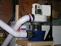
FWIW, I just did an upgrade on my similar generation 2hp Delta. It was better shape, but was blowing fines around through the bag.
After much reading I settled on this course of action:

  1. Remove throat plate restrictor (these were added to some Deltas because people were running without bags and burning up motors);
  2. Add Thein baffle at top of cone and before filter;
  3. Add Winn-style pleated filter--Donaldson P182038 Air Filter
It now pulls better, runs slightly quieter and definitely releases fewer fines into the air. I'm also getting almost no swirling in the bottom of the plastic dust catching bag.

The Thein baffle discussion is a bit of a rabbit hole, and many people are using them as part of a pre-separator. However the problem with adding either a cyclone or Thein style pre-separator is pressure drop (and for my purposes, takes up more space) so I compromised with keeping the DC within the original dolly--I don't even really have a good place to wall mount, since the other tweak is to mount the blower directly as possible to the cone.

I'm also in agreement with MikeK--the pleated filter is the big efficiency improvement because you are adding all of that surface area and reducing the back pressure on the blower (as well as catching finer particles)--but I'm still running a Jet filter to pick up airborne particles.
 
Last edited:
To avoid these ads, REGISTER NOW!

Firstram

Well-known member
Joined
May 16, 2017
Messages
1,392
If its below 15 its will only go lower once I add restrictions, leaving precious cfm's on the table since its not working at its full potential.

If this is the case I will put on a bigger impeller and check the amps again wide open until its overloaded. Then add restrictions until its pulling 15amps at the tool. If my calculations are correct, that should make maximum cfms.
That housing won't really support a larger impeller. If you want to load the motor and draw more air, open the inlet to 7". You can cut a 3/4 plywood disk for the inlet to test with and keep the factory unaltered.
 
OP
E

Enigma

Well-known member
Joined
Sep 2, 2010
Messages
861
Location
Florida
why wont it support a bigger impeller? its 12" and there looks like 3" of space on each side of the impeller. i would like to try 15" i just got my clamp on ammeter. i can make a disc of plywood like you said and check the amps both ways.
 

Attachments

  • 20220423_154334.jpg
    20220423_154334.jpg
    413.7 KB · Views: 16

MikeK

Well-known member
Joined
Oct 6, 2020
Messages
414
Location
Germany
why wont it support a bigger impeller? its 12" and there looks like 3" of space on each side of the impeller. i would like to try 15" i just got my clamp on ammeter. i can make a disc of plywood like you said and check the amps both ways.

Good luck with fitting a 15-inch impeller on a 2HP motor. You might want to do a bit more research on the Pentz website and visit the Dust Extraction subforum on the Australian WoodWork Forums before you get too far ahead of yourself. BobL on the WWF is a retired physicist and is a leading expert on dust extraction and collection. What he doesn't know about woodshop dust extraction is not worth knowing.

There might be three inches of space on each side of the impeller when it is attached to the motor shaft inside the housing, but the impeller has to fit through the opening in the blower housing first. I don't think you will come close to wedging a 15-inch impeller in that housing unless you drastically modify the blower housing, such as splitting it.

If you did manage to fit the 15-inch impeller, the extra three inches in the impeller diameter equates to much more mass than your current impeller and I doubt your 2HP motor will ever reach full speed before the circuit breaker opens or the motor burns up. Based on my limited research with larger DC systems, such as Oneida and Clear Vue, spinning a 15-inch impeller appears to require at least a 5HP motor, and ideally a 7.5HP motor. Both of these exceed the capacity of residential 120VAC electrical distribution systems. You might find a 5HP motor rated for single phase 230V, but it will likely require a 30A service. The 7.5HP motor will certainly require 120/208V three-phase service.

The most common impeller upgrade for the Harbor Freight 2HP blower with the 10-inch impeller is the Rikon 60-200 impeller. I really don't see anything wrong with your current blower assembly. The impeller has the backward curved blades, which is ideal for reduced noise and improved efficiency. My advice is:

  • Forget the bells, whistles, racing stripes, chrome kick stands, and handlebar tassles. These do not add to the function of the DC system.
  • Buy (or find) a cyclone separator such as the Oneida Super Dust Deputy with the 5-inch inlet and 6-inch outlet. I never had any success with the Thien separators.
  • Mount the blower as close to the top of the cyclone as you can, preferably directly on the cyclone.
  • Connect the bottom of the cyclone to a metal 35-50 gallon airtight bin or barrel to collect the dust and chips.
  • Either vent the output of the blower outside your shop or buy a large pleated filter with at least a MERV 15 rating. Forget about using any bag filter that will just dump the bad stuff back into your shop. The bad stuff is in the 1 to 2.5 micron size, so your 30 micron bag won't even be a speed bump as the dust makes a beeline for your lungs. The cyclone will do a good job of stopping most of it, but some does make it through and there's no point in making it easy to get back into your shop.
  • Use 5-inch PVC storm drain as the main distribution trunk for your shop and the shortest length of flexible hose to connect to the machine. Metallic duct tape works great for sealing the connections of the PVC joints.
  • If you want to make a mobile DC system that you can move from machine to machine, you can forget about the PVC and use a short length of flexible hose to connect to the machine. There are plenty of YouTube examples DC carts that have the cyclone, dust bin, pleated filter, and blower assembly as one compact unit.
 

Firstram

Well-known member
Joined
May 16, 2017
Messages
1,392
why wont it support a bigger impeller? its 12" and there looks like 3" of space on each side of the impeller. i would like to try 15" i just got my clamp on ammeter. i can make a disc of plywood like you said and check the amps both ways.
MikeK made good points.

A larger impeller would be so tight in that housing it would sound like an air raid siren, seriously!
 
OP
E

Enigma

Well-known member
Joined
Sep 2, 2010
Messages
861
Location
Florida
Well Mike ya Im getting a little ahead of myself here, after all I havent event checked the running amps yet. I got my amp meter today but I need to make a special extension cord that allows me access to the individual wires so tomorrow I will make that and then test the motor wide open and restricted to see what Im working with.

Currently the Jet 1200 single stage DC sits outside when in service where it is free to blow sub 30 micron dust particles through the bag to its hearts delight and into the wind. I have 1600 cfms at the inlet with the bags on. My goal is to have 1000cfm at the tool. I will have a 15 foot main pipe and a 5 foot hose at each tool which will have its own gate. This system would be just fine for me actually. I dont think I will lose 600 cfms with just that. The only thing Im concerned about with this system is protecting the impeller.

I know in the bag there is nothing smaller than 30 microns so that should be safe since the dangerous ones are the 1 to 2.5 micron ones that have passed through the bag and into the wind. The bag is easy enough to change. I washed them both in the washing machine after blowing them with compressed air out in the yard. 27 years of seasoning removed so that bag can now breath the fines away into the wind.

I would like some separation though to protect my impeller. If I did have a separator I wouldnt want it to collect the fines. I would want it to only collect visible dust so it doesnt have to have a physicist design it. Just a simple homemade baffle or short cyclone is all I need to protect the impeller and remove the visible sawdust. Then I could forget the bags altogether and just blast the remaining dusts outside through a vent in the wall. That would be ideal and this whole setup would take up much less space also. If I could do that without losing 600 cfms, I think I would do it. Then I could keep my stock impeller.

I have not tried to fit a 15 inch anything in there. You may be right about that. Hopefully 12 inches will be enough. They probably arent cheap either. Lots to think about. Thank you for your input into my project.

Alternately I could keep the system as is and simply add some kind of impeller protector baffle that would only filter out the big pieces and hard objects, nuts bolts screws, tools, wood pieces, etc. stuff that could hurt the impeller or cause a jam. I would be happy with that as well so long as this separator does not rob me of 600 cfm.
 
Last edited:
OP
E

Enigma

Well-known member
Joined
Sep 2, 2010
Messages
861
Location
Florida
MikeK made good points.

A larger impeller would be so tight in that housing it would sound like an air raid siren, seriously!
well i guess its not a priority. i will work with what i have until i find grounds to declare it deficient.
 

BukitCase

Well-known member
Joined
Apr 11, 2017
Messages
1,075
Location
Oregon
I know you're having fun, wouldn't wanna deprive you; however...

Thien Baffle or Cyclone: Efficiency Comparison - YouTube

Posted some of this on another thread, my cyclone mods are on the same size (but more vertical) as the original rolling base on the modded DC1100 (ordered with the pleated filter) - I used all 4" DWV piping, welded up a bracket to mount the motor/impeller vertical.

Point is, you could do a similar setup WITHOUT going much bigger on footprint, and STILL keep it portable so you could use it outside.

Note that even my 90's are really 2 45's - Also, all air, vacuum, 120 and 240 volt power are on drops that, when NOT being used are just above head height. (I HATE floor clutter, even tho I'm usually guilty of it)

The pic showing the bag - that's how much dust made it into the bag in about 15 YEARS. Only thing I've emptied in that time is the 35 gallon barrel. Still pulls everything into the barrel except from my antique table saw and the crappy hood on my DeWalt slider (both are slated for more TLC)

The foot pedal (pics 1,5) lets me lower the barrel far enough to just slide it out (lid and seal stays there) for emptying - there are stops for the barrel so you just push it in to the stops and step on the pedal to re-seal... Steve
 

Attachments

  • ShopDust-1.JPG
    ShopDust-1.JPG
    401.3 KB · Views: 13
  • ShopDust-2.JPG
    ShopDust-2.JPG
    345.8 KB · Views: 13
  • ShopDust-3.JPG
    ShopDust-3.JPG
    333.4 KB · Views: 12
  • ShopDust-5.JPG
    ShopDust-5.JPG
    311.1 KB · Views: 12
  • ShopDust-17.JPG
    ShopDust-17.JPG
    422.9 KB · Views: 11
  • ShopDust-19.JPG
    ShopDust-19.JPG
    401.2 KB · Views: 12
Last edited:
OP
E

Enigma

Well-known member
Joined
Sep 2, 2010
Messages
861
Location
Florida
amps data coming in now.

9.6 amps with no bags and no restrictions. wide open.
9.4amps running with both bags attached. clean and empty.
6 amps with input blocked
6 amps with outlet blocked

the 6 inch inlet cannot be widened unless i replace the cover with a plywood one with a 7" hole.

just in. 10.9 amps with inlet cover removed and no outlet restrictions

so this motor is only working at 66% of its capability. what is the limiting factor? its not the motor.

i think i need a bigger impeller. its got a 12 inch i wonder what the biggest will fit? honestly its tight clearance with the opening so im gonna have to cut the case, install bigger impeller and then weld cover back together. i should open the outlet also.
 
Last edited:

MikeK

Well-known member
Joined
Oct 6, 2020
Messages
414
Location
Germany
amps data coming in now.

9.6 amps with no bags and no restrictions. wide open.
9.4amps running with both bags attached. clean and empty.
6 amps with input blocked

the 6 inch inlet cannot be widened unless i replace the cover with a plywood one with a 7" hole.

so this motor is only working at 66% of its capability. what is the limiting factor? its not the motor.

This looks normal. Your 2-pole motor is designed to rotate at 3450 RPM and will draw as much current needed to accomplish this, within reason. With the loading you applied, the motor required 9.4 to 9.6 A with the column of air passing through the impeller. When you blocked the input, the amount of current required to maintain the 3450 RPM decreased. Again, this is normal.

If you add about 10 meters of 4-inch ducting to the input, you will see the current increase, since the ducting provides airflow resistance. Add a few 45 or 90 degree bends in the ducting, and you will introduce more airflow resistance. You can increase the loading to the point where the motor needs the full rated current to maintain the design RPM. Increasing the load beyond that will result in decreasing RPM, an overheated motor, a tripped circuit breaker, or a fire.
 
OP
E

Enigma

Well-known member
Joined
Sep 2, 2010
Messages
861
Location
Florida
This looks normal. Your 2-pole motor is designed to rotate at 3450 RPM and will draw as much current needed to accomplish this, within reason. With the loading you applied, the motor required 9.4 to 9.6 A with the column of air passing through the impeller. When you blocked the input, the amount of current required to maintain the 3450 RPM decreased. Again, this is normal.

If you add about 10 meters of 4-inch ducting to the input, you will see the current increase, since the ducting provides airflow resistance. Add a few 45 or 90 degree bends in the ducting, and you will introduce more airflow resistance. You can increase the loading to the point where the motor needs the full rated current to maintain the design RPM. Increasing the load beyond that will result in decreasing RPM, an overheated motor, a tripped circuit breaker, or a fire.
why do the amps go down to 6 when i create airflow resistance by covering the inlet?


i justtested my 12" radial saw. 230v 7amps rating. sitting there just spinning the blade its drawing 3 amps. when i give it 3/4 plywood the amps goes up. when i give it 2x4 it goes up again. more wood more amps, less wood less. i imagine the teeth on the blade as fins on an impeller and long hoses and elbows and reducers are not resistance but rather air restrictors. less air, less work to do for the motor. i was shocked when i saw the amps go down when covering the inlet. its counter intuitive to me.
 
Last edited:

MikeK

Well-known member
Joined
Oct 6, 2020
Messages
414
Location
Germany
why do the amps go down to 6 when i create airflow resistance by covering the inlet?


i justtested my 12" radial saw. 230v 7amps rating. sitting there just spinning the blade its drawing 3 amps. when i give it 3/4 plywood the amps goes up. when i give it 2x4 it goes up again. more wood more amps, less wood less. i imagine the teeth on the blade as fins on an impeller and long hoses and elbows and reducers are not resistance but rather air restrictors. less air, less work to do for the motor. i was shocked when i saw the amps go down when covering the inlet. its counter intuitive to me.

The current goes down when you block the inlet of the blower housing because the impeller is no longer moving a column of air past it. There is still a little air in the housing, but if you should feel a noticeable decrease in air from the outlet when you block the inlet.
 
To avoid these ads, REGISTER NOW!
OP
E

Enigma

Well-known member
Joined
Sep 2, 2010
Messages
861
Location
Florida
isnt that the same as using elbows and long runs of pipe and reducers at the tool? but you say amps would go up when i add those. when i simulate that by partially covering the intake, the amps go down. something is not adding up here
 

MikeK

Well-known member
Joined
Oct 6, 2020
Messages
414
Location
Germany
isnt that the same as using elbows and long runs of pipe and reducers at the tool? but you say amps would go up when i add those. when i simulate that by partially covering the intake, the amps go down. something is not adding up here

It's not intuitive, but that's how it is. You just have to accept it. :)

The motor is designed to maintain a constant RPM. Period. As the loading on the motor increases, so does the input current. When the loading on the motor decreases, so does the input current.

When you add restrictions, such as more ducting or elbows, you are still providing a source of airflow to the impeller and the motor has to work harder to maintain the same RPM. When you block off the input to the housing, you are no longer providing a source of airflow and the impeller is spinning in a low pressure zone. Because of the low pressure, there is less air to thrash about and the motor doesn't need as much power to maintain the RPM.

If you were able to put a huge blast gate over the input of the blower housing and monitor the input current, you would be able to test this. You could simulate it with a large piece of plywood. With the impeller spinning, and no restrictions, you would see 9.4 A. As you slide the plywood over the opening, there will be a point where the motor is starting to labor to maintain the RPM and you will see the input current to the motor increase.

If the load continues to increase, the input current will eventually reach the Full Load Ampere (FLA) rating. The FLA is the current required for the motor to produce its full horespower rating at the design RPM. If the load continues to increase, the RPM will drop and bad things might happen to the motor or your electrical distribution if they are not properly protected.

As you continue sliding the plywood over the housing input, the current will peak at some value when the motor is producing the most work to maintain the RPM. As you continue to slide the plywood over the housing input, you will start to starve the impeller and it will be working less to maintain the RPM. The input current will start to drop as will the airflow at the output of the housing. By the time you have completely cover the housing input, there will be very little airflow over the impeller and the input current will be at the 6A level. The airflow at the output of the housing will be very low, if anything at all.
 

Monza Harry

Well-known member
Joined
Dec 29, 2018
Messages
1,433
Location
Windsor ON
Your bigger impeller may not add air flow as the housing does need space to move the air it is pumping that scroll shape isn't an accident it requires that shape for the air to escape more [volume with each fin on the impeller]. Many impellers use the same case for different capacities but the height of the fan would change not normally the diameter (to a point). Also you are presuming that FLA is sustainable, that would be an expensive motor [very high service factor] FLA is usually applicable for a short time only (60-80% I would expect). Not a great plan for a DC with a high service factor ( long duration continuous). Harry
 
OP
E

Enigma

Well-known member
Joined
Sep 2, 2010
Messages
861
Location
Florida
i did not see any increase in amps when partially blocking the input. i will try again.

Your bigger impeller may not add air flow as the housing does need space to move the air it is pumping that scroll shape isn't an accident it requires that shape for the air to escape more [volume with each fin on the impeller]. Many impellers use the same case for different capacities but the height of the fan would change not normally the diameter (to a point). Also you are presuming that FLA is sustainable, that would be an expensive motor [very high service factor] FLA is usually applicable for a short time only (60-80% I would expect). Not a great plan for a DC with a high service factor ( long duration continuous). Harry
some motors opearate at 115% sustained. others at 80% . there is a spec but normally motors for moving materials do not have that limitation. ws reading about it on pentz site
 
OP
E

Enigma

Well-known member
Joined
Sep 2, 2010
Messages
861
Location
Florida
what you are referring to is Service Factor. I read about it on Pentz today. He said

"...all quality motors come with different service factors. A 1.0 service factor motor can run at 100% of its rated amperage without overheating. A motor with a 0.5 service factor should never be run more than half time or it will overheat and can burn up. These low service factor motors are often used for fixed purposes such as opening a gate and have heat sensors that limit how much they can run. Alternatively, a 1.10 service factor motor can run at 110% of its maximum rated horsepower without overheating as long as it is not used in an already hot environment."
 

Monza Harry

Well-known member
Joined
Dec 29, 2018
Messages
1,433
Location
Windsor ON
I'm just going from my experience building things, whenever I built to 100% capacity things didn't last long even when they should have. I couldn't read the tag clearly on my phone so I couldn't read the service factor. Harry
 
OP
E

Enigma

Well-known member
Joined
Sep 2, 2010
Messages
861
Location
Florida
i cant find it either. i dont see it on the tag. i guess i could run it and watch the temp with a infrared thermometer
 

MikeK

Well-known member
Joined
Oct 6, 2020
Messages
414
Location
Germany
i did not see any increase in amps when partially blocking the input. i will try again.

After tossing and turning all night over this, or maybe it was the small pea someone put under my mattress, I think you might not see the drastic changes in the current as you block the input. The impeller does not have a mechanical connection with the airflow and will likely transition quickly from static current to the lower level as the pressure in the housing drops.
 
OP
E

Enigma

Well-known member
Joined
Sep 2, 2010
Messages
861
Location
Florida
Intuition says that resistance/restrictions in the system makes the motor work harder but it actually has the opposite effect. That's why I say it's counter intuitive. It's hard to accept that amps goes down when air flow resistance increases, but we must. When we add elbows, long runs, reducers, cyclones, baffles, narrower ducts, all these things make it easier on the motor, that's why CFM goes down. Restricting the airflow does not make it harder to spin the impeller, it makes it easier. Notions of motors burning up from running the DC with all blast gates closed, is false.

If your 2hp motor has a service factor > 1 and is drawing less than the rated amps wide open with no restrictions, the impeller is too small. With that size impeller a 3, 5, 10, or 50hp motor is not going to make any difference.

My motor draws about 10amps wide open with no restrictions and is rated at 15amps. These types of motors typically have a service factor >= 1. Any slight restriction and the amps start going down.

Without a separator, and with a very minimal 6" system, I believe I will be able to keep 1000cfm at the tool of the 1600 i have at the inlet. I may just keep the DC as is and station it outside so the fines can just float away. Otherwise for the price of a 14" impeller I can modify my DC and put the extra 5 amps to work. Then I could create enough air flow to add a separator and still have 1000cfm at the tool.

Im researching duct work now and where to get the 6" sewer/drain pipe, y's, and smooth wall 6" hose.
 
Last edited:
To avoid these ads, REGISTER NOW!
Top Bottom