I'd either attach it to the wall or to the kiln.OK...so I was able to pickup the Acme T113074 transformer for $45 bucks. It was actually for two of them mounted on a steel frame so I got two and a frame for $45 bucks!
So looking at the schematic, here is what I believe I need to do.
On the input side
Connect H2 & H3 together
Connect one leg from my panel to H1 and the other leg to H4 (Does it matter which leg I connect to H1 or H4?)
Instead of wiring it directly to my panel, can I just put a 6-50 connector on the end and plug it into an existing 240 outlet?
On the output side
Connect X2 and X3 together
Connect one leg of my outlet to X1 and the other leg to X4 (Does it matter which leg I connect to X1 or X4)
Do I need to run a ground wire from my panel to the case or frame of the transformer?
Is it OK for me to mount the 208v outlet directly onto this frame or do I have to mount it to the wall (for code or whatnot)?


You are using an out of date browser. It may not display this or other websites correctly.
You should upgrade or use an alternative browser.
You should upgrade or use an alternative browser.
240v to 208v question
- Thread starter vrinner
- Start date

walta
Well-known member
My calculations says each of the heaters will have a resistance of about 13 ohm. Most multi meters should be acquit for this task. What make and model meter do you have?
I would be reluctant to mess with the connection closest to the element for fear of damaging the element, so I would follow the wires and disconnect the other end of the wire.
Mounting the transformer to the kiln has a few challenges in that you need to keep the transformer cool. Seems like a few inches of air gap a heat shield another air gap should be enough.
Walta
I would be reluctant to mess with the connection closest to the element for fear of damaging the element, so I would follow the wires and disconnect the other end of the wire.
Mounting the transformer to the kiln has a few challenges in that you need to keep the transformer cool. Seems like a few inches of air gap a heat shield another air gap should be enough.
Walta
BillK
Well-known member
I read the thread from the beginning. If you look at the manufacturers site for that transformer it tells you all about buck/boost and the one he bought appears to have an output of 16 or 32 volts ????At least make an attempt to read the thread, this is exactly what has been suggested.
After looking at the installation instructions I see where it can be used to do what he wants to do. BUT I still dont think its the correct way to do it with his three phase unit.
American Locomotive
Well-known member
Yup, connect H2 & H3 together. H1 and H4 go to L1 and L2.On the input side
Connect H2 & H3 together
Connect one leg from my panel to H1 and the other leg to H4 (Does it matter which leg I connect to H1 or H4?)
Yes. Just an example: L1 will go directly to the L1 side of the outlet, L2 will go into X1, and then X4 will go to L2 connection on the outlet.On the output side
Connect X2 and X3 together
Connect one leg of my outlet to X1 and the other leg to X4 (Does it matter which leg I connect to X1 or X4)
It does matter which way you hook it up. One way will boost the voltage (240 > 272) the other way will buck the voltage (240 > 208). Hook it up and measure the voltage at the outlet. If it's increasing the voltage, just swap the X1 and X4 connections to switch what the transformer does. You could also reverse the transformers input H1/H4 connections as well. Doesn't matter - whichever is easier.
wyliesdiesels
Well-known member
not sure which chart youre looking at but its incorrect for bucking 240 down to 208.Yup, connect H2 & H3 together. H1 and H4 go to L1 and L2.
Yes. Just an example: L1 will go directly to the L1 side of the outlet, L2 will go into X1, and then X4 will go to L2 connection on the outlet.
It does matter which way you hook it up. One way will boost the voltage (240 > 272) the other way will buck the voltage (240 > 208). Hook it up and measure the voltage at the outlet. If it's increasing the voltage, just swap the X1 and X4 connections to switch what the transformer does. You could also reverse the transformers input H1/H4 connections as well. Doesn't matter - whichever is easier.
according to page 10, he needs to use figure I for bucking, which is found on page 17
So L1 goes to H4 and L2 goes to X1
Then connect H3 to H2 and X3 to X2
His load wires go to H4 and H1/X4
Although my unit is currently 3 phase, I can (and am) easily convert it to single phase with a couple of parts from the manufacture. They were very clear on this.I read the thread from the beginning. If you look at the manufacturers site for that transformer it tells you all about buck/boost and the one he bought appears to have an output of 16 or 32 volts ????
After looking at the installation instructions I see where it can be used to do what he wants to do. BUT I still dont think its the correct way to do it with his three phase unit.
As others have stated as well as does the selection chart from the manufacture, it does do 208 and as previously explained 240 - 32 = 208v.

I have this Sperry DM-305A multimeter.My calculations says each of the heaters will have a resistance of about 13 ohm. Most multi meters should be acquit for this task. What make and model meter do you have?
I would be reluctant to mess with the connection closest to the element for fear of damaging the element, so I would follow the wires and disconnect the other end of the wire.
Mounting the transformer to the kiln has a few challenges in that you need to keep the transformer cool. Seems like a few inches of air gap a heat shield another air gap should be enough.
Walta
How would I measure the ohm...Sorry...if not obvious from all my questions, all I ever really ever do is check continuity with this thing...lol.

BillK
Well-known member
I have this Sperry DM-305A multimeter.
How would I measure the ohm...Sorry...if not obvious from all my questions, all I ever really ever do is check continuity with this thing...lol.
Turn it one click counterclockwise to the 200 ohm range and connect your test leads to the elements. You really need to disconnect at least one side of the element to get a proper reading.
grounded-b
Well-known member
OK...so I was able to pickup the Acme T113074 transformer for $45 bucks. It was actually for two of them mounted on a steel frame so I got two and a frame for $45 bucks!
So looking at the schematic, here is what I believe I need to do.
On the input side
Connect H2 & H3 together
Connect one leg from my panel to H1 and the other leg to H4 (Does it matter which leg I connect to H1 or H4?)
Instead of wiring it directly to my panel, can I just put a 6-50 connector on the end and plug it into an existing 240 outlet?
On the output side
Connect X2 and X3 together
Connect one leg of my outlet to X1 and the other leg to X4 (Does it matter which leg I connect to X1 or X4)
No. This is NOT correct. Wiring it that way, will convert 240V down to 32V.
You need to find a "buck/boost" wiring diagram. You do not use the diagram on the nameplate
mike93lx
ALLIANCE MEMBER
...
Could be. In the industry I work in, a grand is basically a few dollars.I think that everyone is missing this comment in your original post.
This comment tells me that it isnt a simple swap.
wyliesdiesels
Well-known member
I already pointed to the diagram he needs to use as spelled out by sq dNo. This is NOT correct. Wiring it that way, will convert 240V down to 32V.
You need to find a "buck/boost" wiring diagram. You do not use the diagram on the nameplate
walta
Well-known member
Turn the knob on the meter until the red arrows line up. Then touch the two probs together the display should change from “OR” or “OL” to a number close to zero any number under ten is close enough for this test.
Note move the black wire to the center hole and never ever put a wire in the left hole again
Please post a photo of the heater wires.
Walta
Note move the black wire to the center hole and never ever put a wire in the left hole again
Please post a photo of the heater wires.
Walta
Attachments

wyliesdiesels
Well-known member
its actually simpler than you think.Here are all the relevant sections from the manual for my specific unit, T113074.
For Bucking from 240 to 208
See connection diagram page 136 section I
Then on 136 diagram I...I wont even try and give my interpretation of that...maybe someone else can.

youre inputting 240v across a coil that is rated for 240v (H4 to H1) as well as a coil rated for 32v (X4 to X1). so the total potential across the 2 coils connected in series is 240v.
Then when you connect your load wires to H4 and H1/X4, youve removed the coil that is rated for 32v thus subtracting 32v from the original 240v potential across the 2 combined coils. thus you get 208v
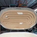
OK...here are pics of the kiln lid...does have some of the ceramic stuff missing.Turn the knob on the meter until the red arrows line up. Then touch the two probs together the display should change from “OR” or “OL” to a number close to zero any number under ten is close enough for this test.
Note move the black wire to the center hole and never ever put a wire in the left hole again
Please post a photo of the heater wires.
Walta
I put the arrow on my meter where you said and move the wires. The display did not change to OR or OL, just read 1. But I measured and they both are at the lowest 15.4

walta
Well-known member
Logic says there should be 3 heating elements in a 3-phase kiln but I see 2 elements and that maybe all there are.
When the meter is set to OHMs and the probes are not touching each other the display should indicate infinite resistance with some combination of letters each brand is different. When you touch the probes together ideally it would read zero but not so much in real life. This is an important test so we know if your meter is working correctly and note how far from zero it is reading.
It is difficult to test the resistant of the elements without disconnecting one of the wires from each element because electricity may flow thru other parts of the circuit and confuse you with a reading making you believe a failed part is good wnen it is not.
Do you have a diagram for the kiln?
Walta
When the meter is set to OHMs and the probes are not touching each other the display should indicate infinite resistance with some combination of letters each brand is different. When you touch the probes together ideally it would read zero but not so much in real life. This is an important test so we know if your meter is working correctly and note how far from zero it is reading.
It is difficult to test the resistant of the elements without disconnecting one of the wires from each element because electricity may flow thru other parts of the circuit and confuse you with a reading making you believe a failed part is good wnen it is not.
Do you have a diagram for the kiln?
Walta
There are three elements. There is one more in the bottom part of the kiln.Logic says there should be 3 heating elements in a 3-phase kiln but I see 2 elements and that maybe all there are.
When the meter is set to OHMs and the probes are not touching each other the display should indicate infinite resistance with some combination of letters each brand is different. When you touch the probes together ideally it would read zero but not so much in real life. This is an important test so we know if your meter is working correctly and note how far from zero it is reading.
It is difficult to test the resistant of the elements without disconnecting one of the wires from each element because electricity may flow thru other parts of the circuit and confuse you with a reading making you believe a failed part is good wnen it is not.
Do you have a diagram for the kiln?
Walta
When I put the meter to the OHMs setting as instructed, the LED reads the number 1 and then a little decimal to the right...nothing else.
When I put the two probes together then numbers drop rapidly to .1, if I put the meter on 2K setting it will read to like .004 or something like that.
I did disconnect the control module from the elements so it just measured the resistance from the element.
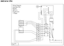
Here is the wiring diagram for the kiln as it is currently configured with 3 phase.

Here is the wiring diagram for the kiln as it WILL BE configured with single phase. I have ordered the appropriate parts from the manufacture to make it work in single phase. They were very clear that a 3 phase can be converted to a single phase.
walta
Well-known member
Ok it sounds like you meter is working and you understand how to read it.
After looking at the diagram I no longer think it is necessary to disconnect wires to test the elements.
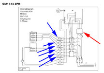
Can you find the terminal 1-6 in this diagram with the blue arrows?
You should measure from 1 to 2, 3 to 4, 5 to 6 and get similar reading on all 3 of more than 5 Ohms and less than 20 Ohms that would indicate the elements are good, If the meter display remains unchanged when connected that would indicate a bad element.
It does look like changing from 3 phase to single should be easy by moving two wires.
The red arrow in the diagram is a transformer please try to locate it and post a photo of any words and numbers on the transformer.
Walta
After looking at the diagram I no longer think it is necessary to disconnect wires to test the elements.
Can you find the terminal 1-6 in this diagram with the blue arrows?
You should measure from 1 to 2, 3 to 4, 5 to 6 and get similar reading on all 3 of more than 5 Ohms and less than 20 Ohms that would indicate the elements are good, If the meter display remains unchanged when connected that would indicate a bad element.
It does look like changing from 3 phase to single should be easy by moving two wires.
The red arrow in the diagram is a transformer please try to locate it and post a photo of any words and numbers on the transformer.
Walta
Attachments
Last edited:

ez-duzit
Well-known member
Yeah, I see how they're doing it.....
It does look like changing from 3 phase to single should be easy by moving two wires...
walta
Well-known member
Transformer looks good.
Next question is where does the wire with the green arrow belong and why was it disconnected? Please follow the wire and find the other end and what it is connected to. Maybe a ground wire.
Take a sharpie marker and color the wire red with the red arrow. Follow the wire to the other end and color it red.
Take a sharpie marker and color the wire black with the black arrow. Follow the wire to the other end and color it black.
Then post a photo of the wires.
Walta
Next question is where does the wire with the green arrow belong and why was it disconnected? Please follow the wire and find the other end and what it is connected to. Maybe a ground wire.
Take a sharpie marker and color the wire red with the red arrow. Follow the wire to the other end and color it red.
Take a sharpie marker and color the wire black with the black arrow. Follow the wire to the other end and color it black.
Then post a photo of the wires.
Walta
Attachments

The green wire was connected to the ground on the power cable which I have removed to replace.Transformer looks good.
Next question is where does the wire with the green arrow belong and why was it disconnected? Please follow the wire and find the other end and what it is connected to. Maybe a ground wire.
Take a sharpie marker and color the wire red with the red arrow. Follow the wire to the other end and color it red.
Take a sharpie marker and color the wire black with the black arrow. Follow the wire to the other end and color it black.
Then post a photo of the wires.
Walta

The red wire goes to the left set of terminals, bottom right
The black wire goes to the right set of terminals, bottom left

walta
Well-known member
Now mark red on the wire with the new red arrow this wire is on the lower left terminal. Find and mark the other end it should go back to the same terminal block.
Do the same for the black arrow on the lower right terminal.
Post another photo and we will be ready to move the wires around for single phase.
Walta
Do the same for the black arrow on the lower right terminal.
Post another photo and we will be ready to move the wires around for single phase.
Walta
Attachments

Here is the second red.Now mark red on the wire with the new red arrow this wire is on the lower left terminal. Find and mark the other end it should go back to the same terminal block.
Do the same for the black arrow on the lower right terminal.
Post another photo and we will be ready to move the wires around for single phase.
Walta

It goes here

Then the black

It goes here
walta
Well-known member
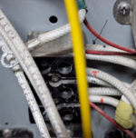
Next, we need to move the two wires in the center of the power block.
Let’s add a second red and black dot to those two wires.
Then move the wire with 2 red dots to the where the red arrow is in this photo
Same for the black wire and arrow.
Now the kiln will run on single phase.
Do you have a 240-volt 40-amp receptacle?
Do you have a plug and cord to fit the receptacle?
Walta
Let’s add a second red and black dot to those two wires.
Then move the wire with 2 red dots to the where the red arrow is in this photo
Same for the black wire and arrow.
Now the kiln will run on single phase.
Do you have a 240-volt 40-amp receptacle?
Do you have a plug and cord to fit the receptacle?
Walta
Attachments

So I have an existing 40 amp circuit with a 14-50R outlet that I have my air compressor hooked up to.
My thought is to put a put a 50 amp plug on one end of the transformer and a 50 amp outlet on the other end. Kind of like a mini extension cord with transformer in the middle.
Plug the transformer into existing air compressor outlet
Plug kiln into the 50 amp outlet coming off the transformer
My thought is to put a put a 50 amp plug on one end of the transformer and a 50 amp outlet on the other end. Kind of like a mini extension cord with transformer in the middle.
Plug the transformer into existing air compressor outlet
Plug kiln into the 50 amp outlet coming off the transformer
walta
Well-known member
The math says this kiln will draw 34.6 amps at 240 Volts if your voltage happens to be exactly 240 volts and if the transformer has zero losses which is impossible. Generally, the voltage tends to run about 7% higher and transformers about the same making it a 40 amp load . It would be a code violation and a bad idea use more than 80% of the breaker rating. Even a 50 amp circuit is pushing the limit for a 40 amp load.
Seem to me you need to upgrade the circuit. What gage wire did they run maybe you just need a breaker.
Seems to me you should hard wire the kiln to the transformer and plug the transformer into the outlet. If not someone might accidently plug in the kiln in without the transformer.
Walta
Seem to me you need to upgrade the circuit. What gage wire did they run maybe you just need a breaker.
Seems to me you should hard wire the kiln to the transformer and plug the transformer into the outlet. If not someone might accidently plug in the kiln in without the transformer.
Walta
American Locomotive
Well-known member
Kiln should be hard wired to transformer.
As mentioned, it will probably trip the breaker running the Kiln for more than 10-15 minutes or so on a 40A circuit. Need 50A.
As mentioned, it will probably trip the breaker running the Kiln for more than 10-15 minutes or so on a 40A circuit. Need 50A.
Sounds like a good idea on hard wiring the kiln. Mistakes happen for sure.The math says this kiln will draw 34.6 amps at 240 Volts if your voltage happens to be exactly 240 volts and if the transformer has zero losses which is impossible. Generally, the voltage tends to run about 7% higher and transformers about the same making it a 40 amp load . It would be a code violation and a bad idea use more than 80% of the breaker rating. Even a 50 amp circuit is pushing the limit for a 40 amp load.
Seem to me you need to upgrade the circuit. What gage wire did they run maybe you just need a breaker.
Seems to me you should hard wire the kiln to the transformer and plug the transformer into the outlet. If not someone might accidently plug in the kiln in without the transformer.
Walta
It's 8 gauge wire from my 40 amp circuit. Based on that and comments above and looking online, I think I need 6 gauge wire. The run from my panel to the outlet is only about 6 feet.
wyliesdiesels
Well-known member
run new wireSounds like a good idea on hard wiring the kiln. Mistakes happen for sure.
It's 8 gauge wire from my 40 amp circuit. Based on that and comments above and looking online, I think I need 6 gauge wire. The run from my panel to the outlet is only about 6 feet.
OK...so I think I have the transformer all wired up properly and ready to test before I hook it up to the kiln (after I swap around wires as per above instructions).
Question on the power cable and the wall outlet.
Even if I did buy a plug with 4 connectors, the transformer and the kiln do not require it.

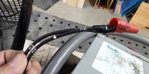
Here are pictures of how I connected everything. Although in my picture above I don't show the ground wires, they are both ground to the case.


Question on the power cable and the wall outlet.
- The wall outlet is a 14-50 and it has 4 terminals. 1 ground (green), two hot (red and black) and 1 neutral (white). (I'm assuming colors and descriptions based on the package instructions and assuming I need to connect all 4 wires).
- The power cable that came with my kiln has 4 wires, 1 ground, two hot and 1 neutral
- The plug I got to put on the end of my cable only has three, 1 ground and two hot.
Even if I did buy a plug with 4 connectors, the transformer and the kiln do not require it.
Here are pictures of how I connected everything. Although in my picture above I don't show the ground wires, they are both ground to the case.
ez-duzit
Well-known member
Looks like you don't need the neutral.
wyliesdiesels
Well-known member
whats with the tape under the wire nuts?
When it was wired for 3 phase it had 3 hots, and ground no neutral. Now you have 2 hots and ground.
Need to check the size of the cord if you are reusing it. It was sized to the 3 phase current and probably isn't big enough on single phase.
Need to check the size of the cord if you are reusing it. It was sized to the 3 phase current and probably isn't big enough on single phase.
The transformer was used and they taped the wires together and then put the wire nuts on. I just repeated what they did.whats with the tape under the wire nuts?
I'll check the cord size, the wires seemed pretty big (bigger than the new 6 gauge) but I'm sure "it looked fine to me" has been said way too many times after the fact so I will check that out tonight.
If I haven't said it before, I really appreciate all the input on this. I'm sure for others this is just a simple thing but I want to make sure it's done right.
walta
Well-known member
It looks to me like your diagram and wiring is wrong.
See this diagram note there is a 50% chance my diagram will boost instead of bucking. In other words, there is a 50% chance you will input 240 volts and have an output 272 volts as opposed to the 208 you are looking for. You want to test the transformer with the kiln disconnected to avoid the possibility of damage to the kiln. If you measure more voltage than you expected reverse the wires on X1 and X4.
Walta
See this diagram note there is a 50% chance my diagram will boost instead of bucking. In other words, there is a 50% chance you will input 240 volts and have an output 272 volts as opposed to the 208 you are looking for. You want to test the transformer with the kiln disconnected to avoid the possibility of damage to the kiln. If you measure more voltage than you expected reverse the wires on X1 and X4.
Walta
Attachments


walta
Well-known member
Note more likely than not your input voltage will be more than 240 volts by as much as 10% so you start at 264 and end at as much as 229 if it is that high, we could use both transformers to reduce it by another 16 or 32 volts
Please measure and post your supply voltage.
Walta
Please measure and post your supply voltage.
Walta
