To avoid these ads, REGISTER NOW!

Between 265 & 485 SQ/FT Two sheds in a trenchcoat

Workspaces sized between 265 and 485 squarefeet.

born to die

Member
Joined
Jun 20, 2022
Messages
23
Location
California
I moved into a cabin early in the pandemic, and unfortunately garages are scarce in this neck of the woods. It's my first place, and I was lucky to snag anything, much less everything that I wanted. So I'll be building the shop space I need. The house was built by an architect (for himself) in the early 40s, along with a 60' wood bridge to get to the lot. It's a "tom thumb" layout, 720 sqft. I've read that it's the minimum size FHA would finance post-war, which explains why so many of the houses I looked at were exactly that size.

Wood prices were out of control when I got started, so my first design was based on a Quonset backbone. I figured they were used in the war, it wouldn't look out of place next to a post-war house. I'm in a moderate fire zone, so steel is a good material on that front, plus the round profile gives embers nowhere to collect. Concrete delivery is a non-starter here (plus we aren't allowed to displace much soil), so I used helical piles and steel beams, then corrugated decking with a block stem wall and 3" self-pour on top. The piles would allow me to site it wherever I wanted without much $ penalty, so I figured I'd put it against a steep drop overlooking a creek.

I eventually ruled it out. I got a surprisingly high quote from Steelmaster, and also learned that our county only allows an owner/builder to design with wood. It's a mixed message -- they want us to move away from wood (to prevent wildfires), but they've made that path more difficult and expensive. Engineers, subcontractors, and scrutiny... no thanks. It wasn't any cheaper than building with RC/green lumber anyways. Maybe this all should have been obvious, but it's my first house and first time worrying about code.


dji_0076.jpgonsite.pngisomat.pngreariso.pngrearmat.png
 
To avoid these ads, REGISTER NOW!
OP
B

born to die

Member
Joined
Jun 20, 2022
Messages
23
Location
California
So round two-- I moved the site to a flatter patch of earth right next to the house. I was way above my scant budget with the last attempt, and I figure the constraints of the smaller area will force reasonable design decisions.

The size & shape is dictated by setbacks from the house, the looming redwoods, and my leach field (that's why it recedes on the right side). It's as large as it can be in that space, but IMO a good size to avoid upstaging the house. I'm a one-car guy, so it's big enough. Limitations keep me focused.

I also don't want the roofline to obstruct the approaching view of the stone chimney. The original builder was deliberate about siting and window placement, so keeping light in those right hand windows is important too. I set the roof pitch to start and end at the same elevations as the house's overhangs, so the chimney will peak well above the shop roofline. And hopefully the lines will resolve with the house in-person.

I continued the siting scheme from the main house -- no windows and total privacy on the southern (neighbor-facing) side, clerestory windows on the northern side for year-round soft light. I found a large aluminum picture window to have a view of the creek. It opens up on the back, Usonian style.

I also copied the post & beam framing from the main house, but beefed it up to 6x. The house is framed with true 4x4 redwood, 2x4 rafters, everything is undersized by timber frame standards. The rafter tails are 24" on both structures, I've already bought the same asphalt tile and green drip edge, etc.


compR.png
 

Attachments

  • reariso.png
    reariso.png
    514.4 KB · Views: 170
  • compsite.png
    compsite.png
    258.1 KB · Views: 210

MadeByMiller

Well-known member
Joined
Dec 29, 2018
Messages
1,230
Location
Rapid City, SD
Neat project! I'm a big fan of the Quonset hut design, but your second design is perhaps more fitting to your home (which is awesome by the way!). I'm curious what software you used to design the structures, the renders are great.
 
OP
B

born to die

Member
Joined
Jun 20, 2022
Messages
23
Location
California
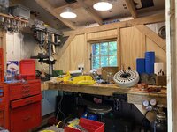
I started out with a downsized shed using a similar design. I'm waiting for 6x6 and 6x8 timbers to be milled for the garage, besides I really needed to get my tools out of my living room. Most of this mess is bound for the garage, but the clutter is still driving me crazy. The shed will be dedicated to woodworking/landscaping when the garage is ready.

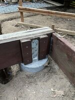
Same basic idea, same 12" board/batten, but without overhangs. I decided to site it somewhere a little dramatic since I lost the steep siting for my garage. I directly buried 4x4's to avoid 6'+ sonotube pours, and used a tree as one of the piers. I'll have to go back in a few years and add proper above-grade concrete piers.

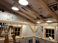
The insulation I bought for the garage was rotting away outside, so I insulated all 6 surfaces. It's now the most comfortable room I have. Made the lighting out of EMT and some screw-in pendants from the 60s.

B378BDCE-A494-467D-A239-3C81B69C7851_1_105_c.jpegE606007F-49DA-4E6D-9A61-0EDFC7565092_1_105_c.jpegBE83DC10-4A33-46C2-A534-D4817E245D33_1_105_c.jpeg8F7F77FF-05D5-4A02-A9E1-635FDD24DA19.jpegCC39FF37-3740-42AC-B632-96264F16A113_1_105_c.jpeg741C1F9D-36EF-43C6-8E2A-61909B256DB7_1_105_c.jpeg2C68027D-0FAF-49FC-8ADA-DE65F5E37EB2_1_201_a.jpegIMG_0938.JPG8B8970A8-341A-4485-9B03-75A9353E0BF3.jpegBEBB6E50-2E46-413E-B84C-0B480BC8F4A6.jpeg
 
OP
B

born to die

Member
Joined
Jun 20, 2022
Messages
23
Location
California
I'm curious what software you used to design the structures, the renders are great.

I'm just using sketchup. On the comps with my home in the background I exported pngs and combined them in photoshop so I could control transparency. I used to do a little bit of arch-viz, but never learned real CAD (or vray) so I tried to find ways to lean into SU limitations. Clay renders always look good, if I'm feeling lazy 😂


inventori_15.png
 
OP
B

born to die

Member
Joined
Jun 20, 2022
Messages
23
Location
California
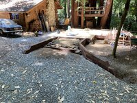
I'm finishing up the foundation/floor right now, so I'll recap what I've done so far. Here's the foundation plan. Eleven concrete piers, 2x10 PT framing, and 1 1/8" Advantech. I also bought some of the cheap Home Depot foam insulation for the cavities.

foundation.png

I didn't have to do much/any grading. I did have to fell a maple and dig out the roots as much as possible. I had help with that part.

IMG_0959.JPGIMG_0958.JPG

Then string and batter board, a 360 level made that much easier that I'm used to. Started from one corner and measured diagonals, adjusted nails, until I could make it around and be within 1/16th on the last nail. A corner level might have helped here. I used a 12" sonotube remnant, centered it with a plumb bob at the location of each pier, and sprayed inside the form to get an accurate 12" dig template on the dirt. More accuracy than I needed, for sure.

IMG_0712.JPG

The piers are 12" sonotubes, footings were created by digging a bell shape into the bottom, bigfoots were way too expensive. I made cages out of #4 rebar and mesh using an 8" sonotube as a form. I forgot to photograph this, but I used zip ties to secure the rebar spaced evenly around the sonotube. I started off tying the wire mesh onto the rebar with a safety wire tool, then realized how long it would take and started welding it together. I know you aren't supposed to do that, but I wasn't convinced I should care for a workshop. I cut them to length for each hole and sat them on dobies. The 360 level was a lifesaver here, too. All the forms are at their finished height, level and plumb.

IMG_0745.JPG
 
OP
B

born to die

Member
Joined
Jun 20, 2022
Messages
23
Location
California
The beam seats are offset, because they were made for a nominal 6x6, and I wanted my (actual) 4.5 of material centered on each pier. The real part # for this application is prohibitively expensive (several multiples of the lumber it was holding), so I used a post holder. It's 10ga steel, which is beefier than what you buy at home depot. But real beam seats cost nearly $200+ each and are made of 1/4" material.

Since the material offset is on the inside of the frame, I set the string grid for the outside profile of the rim joists. Even more use of the 360 laser (and a bubble level) to fine tune the brackets while the concrete was setting. I wet-cured it under plastic for a week.

810E6572-E0F6-4DA8-9084-733914E1F5C0.jpeg

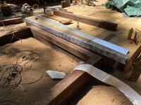
Then framed out the joist assembly. Nothing exciting here except some creative joints to save on lumber. I glued and nailed the beams from end to end, justifying the top edge as I went. The PT fir we get here is wildly inconsistent. I doubled the joist where the car will enter the shop just because. For the first time ever I re-treated the cut ends, not sure how I avoided learning that until now.

IMG_0863.JPG IMG_0876.JPG

Before moving to insulation I marked and drilled the paths of in-floor romex in two colors, 120 & 240. Wire is expensive, trying to take the shortest path for each circuit. Also trenched 24" for direct burial mobile home feed. The dog likes to help me dig holes, and it's legitimately helpful most of the time. He was making the trench wider and not deeper, so I had to ask him to sit it out.

IMG_0920.JPG
 

Sumboodie

Well-known member
Joined
Mar 20, 2021
Messages
10,742
Location
AK
I moved into a cabin early in the pandemic, and unfortunately garages are scarce in this neck of the woods. It's my first place, and I was lucky to snag anything, much less everything that I wanted. So I'll be building the shop space I need. The house was built by an architect (for himself) in the early 40s, along with a 60' wood bridge to get to the lot. It's a "tom thumb" layout, 720 sqft. I've read that it's the minimum size FHA would finance post-war, which explains why so many of the houses I looked at were exactly that size.

Wood prices were out of control when I got started, so my first design was based on a Quonset backbone. I figured they were used in the war, it wouldn't look out of place next to a post-war house. I'm in a moderate fire zone, so steel is a good material on that front, plus the round profile gives embers nowhere to collect. Concrete delivery is a non-starter here (plus we aren't allowed to displace much soil), so I used helical piles and steel beams, then corrugated decking with a block stem wall and 3" self-pour on top. The piles would allow me to site it wherever I wanted without much $ penalty, so I figured I'd put it against a steep drop overlooking a creek.

I eventually ruled it out. I got a surprisingly high quote from Steelmaster, and also learned that our county only allows an owner/builder to design with wood. It's a mixed message -- they want us to move away from wood (to prevent wildfires), but they've made that path more difficult and expensive. Engineers, subcontractors, and scrutiny... no thanks. It wasn't any cheaper than building with RC/green lumber anyways. Maybe this all should have been obvious, but it's my first house and first time worrying about code.


dji_0076.jpgonsite.pngisomat.pngreariso.pngrearmat.png
Steel Master is the outfit I went with. Was about $35k for a 30x48 building.
 
OP
B

born to die

Member
Joined
Jun 20, 2022
Messages
23
Location
California
Steel Master is the outfit I went with. Was about $35k for a 30x48 building.

Thats who quoted my quonset, it was roughly $20k for the 26x20 backbone and two walls. I'm on track right now to spend 20k all-in on the timber design, from footing to light bulbs. I did shrink the footprint though. I think it would have been a wash in the budget either way. One of the appeals of steel was a lower cost, not sure where I got that assumption from though.
 
OP
B

born to die

Member
Joined
Jun 20, 2022
Messages
23
Location
California
I've got the electrical system mapped out so I can pull circuit feeds in the joists before the subfloor goes on. The interior walls will stay unfinished until I've settled into a routine in the shop, in case individual receptacles need to move.

Electrical Iso.png

I've got 3 circuits:
* 40A/240 compressor
* 20A wall outlets
* 20A ceiling outlets

I'm also considering one more 15A feed that I can control with a line-level thermostat, for panel heaters.
There are two exterior outlets and sconces in the wall circuit. The overhead circuit is wired to 3-way switches directly inside and to the right of each door. I'm matching the height of switches in my home so the muscle memory works everywhere, did the same in the shed.

Why am I not pulling a separate lighting circuit? I'm a huge fan of shaker design, but I'll spare y'all the full rant. Shaker pegs are an example that I'll copy for this shop (they called them pins, hence the misnamed clothes pin). The Pinterest set likes to make coat racks out of them, but the real utility comes when you line every room in your house with them on a 12 inch grid, like they did. Then a single hooked sconce can light every lineal foot of wall in the building, depending on the task. If Sister Martha's bonnet is in the way, just move it to another peg.

The overhead circuit will be a blank canvas for lights and drop cords, as needed. I'm installing L5-20 Hubbell twist lock receptacles in most of the rafter bays. I bought decommissioned pendants from a Wendy's, which will be wired to L5-20 plugs. I'm also making four drop cords, L5-20 to 5-15. I'm betting I'll move the lights around a couple times at most, but it saves me from committing before I get to work in the space, and it allows me to change my mind down the road.


s-l1600.jpeg 8C66AC7B-48FE-4C35-912C-6867948BE324_1_201_a.jpeg

Minor annoyance is switched overhead outlets, but if I need something running while I'm gone it can live on the wall circuit.
 

Sumboodie

Well-known member
Joined
Mar 20, 2021
Messages
10,742
Location
AK
Thats who quoted my quonset, it was roughly $20k for the 26x20 backbone and two walls. I'm on track right now to spend 20k all-in on the timber design, from footing to light bulbs. I did shrink the footprint though. I think it would have been a wash in the budget either way. One of the appeals of steel was a lower cost, not sure where I got that assumption from though.
Mine is just for storage. My shop is another building that is a little bit smaller.
 
OP
B

born to die

Member
Joined
Jun 20, 2022
Messages
23
Location
California
Got the 1.5" foam installed in each bay, was going for a friction fit so none of them are perfectly square. Then pointed the edges with silicone. While I was laying subfloor I stepped through a couple of them like a trapdoor and had to reset them. Also pulled the floor feeds, added a t-stat controlled circuit that will run to heater-dedicated outlets on each side of the shop.

IMG_0989.JPG IMG_0992.JPG


I had to lug the 1-1/8 Advantech into place myself, I'd say 125 pounds is no problem but my knees don't agree. I spent time making a stilt to pivot sheets upwards. I didn't have anyone to help drop them into place so this helped me avoid smearing the glue.

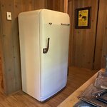
I'm now waiting for the rest of my lumber (these pics are a week old), so I finished up the appliance backdate in my kitchen. The fridge was completely torn down, new insulation, modern digital control unit, rewire etc. It's quieter and uses less power than the 2007 fridge I removed. The range will need to be rewired eventually, and I'll have to decide whether to plumb propane into the kitchen to use the griddle. The oven was made out of the best components of two identical units I bought on craigslist.

IMG_0963.JPG IMG_0326.JPG 65191059900__D2C2FB7A-381E-44A9-B77E-D29893A0553E.JPG 227B703B-C728-4F99-86CF-2747080152CA_1_102_o.jpeg
 
Last edited:
To avoid these ads, REGISTER NOW!
OP
B

born to die

Member
Joined
Jun 20, 2022
Messages
23
Location
California
One thing I haven't figured out is how I will transition from driveway grade to finished height (floor is 16" above grade). I was originally thinking a ramp, but the driveway is all curves, so a fabricated ramp would also have to curve if I want to approach it from the existing driveway.

I'm thinking I should just build up the grade approaching the shop. The driveway slopes down from the street to the shop. The driveway and shop floor are at equal elevation about halfway between the street and the shop (15' from the shop door). I'd need to keep earth away from the floor framing, so I figure some sort of retaining wall on 3 sides with an air gap to the wood framing. And aim for a gentle slope away from the shop doors to prevent water from entering.

I don't love the block wall for this house, maybe I could use sleepers instead. If anyone has a better solution here let me know, grading is not in my wheelhouse.


881945E3-B6C6-4914-BC0B-0A01A3E03BEA_1_105_c.jpeg 09205B3A-C515-4863-AD81-C1A4D12A9DC6_1_105_c.jpeg Screen Shot 2022-07-02 at 4.18.35 PM.png
 
OP
B

born to die

Member
Joined
Jun 20, 2022
Messages
23
Location
California
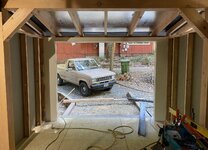
Ended up going with a timber retaining wall to hold the ramp. The right side opens up to meet the driveway curve, then pinches to 8' at the entry doors. The 1/4 yard of fill I picked up didn't get me very far... and I filled the space with boulders first. I'm guessing I need 2 yards+ to fill the rest, thats a lot of trips in the Ranger.

ramp.png IMG_1090.JPG IMG_1104.JPG IMG_1133.JPG

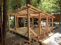
Next up is the main timber frame. The knee braces shrink in proportion with the post heights, partially for head room, partially for a cascading effect when you walk in from the front. The two 6x8 beams that cross multiple bents will support an i-beam chain hoist for engine pulls.

timbers.png crane.png

There will be stick-framed walls in each cavity for electrics, insulation, etc. So no need for girts in the timber frame.

stick-framing.png
 
OP
B

born to die

Member
Joined
Jun 20, 2022
Messages
23
Location
California
Lifting these plates on top of the posts by myself was definitely interesting. Went ahead and routed the wheel channels on the beams that will carry the gantry crane before hanging them up.

On the plate joints I used a "table lap" as a mechanical connection that will resist separation. At least that's how I understand it. Around the time I was cutting the last joint, I finally got the hang of using the beam saw like a (sketchy) router. That, or I finished just in time to not run out of luck.

Instead of the typical flat birds mouth rafter cut, I used a deeper slot that holds the plate on both sides. The idea is that the rafters tie the bents to each other at an equal distance, without fasteners taking any shear stress. After cutting each one separately with a jigsaw, I wished I'd never had the idea. I do think it's stronger though.

Most of the framing is done now, starting on the roof this weekend.


IMG_1203.JPG IMG_1192.JPG IMG_1262.JPG IMG_1260.JPG IMG_1275.JPG
 

MegaVan

Well-known member
Joined
Dec 17, 2020
Messages
274
Location
Ohio
Solo work is tough. I made some mistakes and did a handful of unsafe things before stepping back and rigging an A style shear legs with a chain fall. Everything was much safer after that.
 
OP
B

born to die

Member
Joined
Jun 20, 2022
Messages
23
Location
California
Solo work is tough. I made some mistakes and did a handful of unsafe things before stepping back and rigging an A style shear legs with a chain fall. Everything was much safer after that.

Like this?

Screen Shot 2022-08-11 at 1.04.22 PM.png

I've got a come-along and a chain hoist, really wish I'd done it that way! Could have assembled the bents on the floor instead of building them in the air. While I was researching I saw timber framers build on the ground and lift with a crane, but somehow never came across shear legs.

When I was lifting the plates/beams I used 8' pipe clamps, kept them clamped right below where I was lifting. Sort of like safety lock-outs on a squat rack. So the beams weren't going to fall far, but I still had to lift them myself.
 

FTWingRiders

Well-known member
Joined
Mar 21, 2012
Messages
1,561
Location
Central Ma
Seriously cool build! Lovin’ the post and beam, I built my shop the same, gives it a feel like no other. Love the house and land.. just what I’d like to end up with someday. Working solo is a challenge, I do most of my projects alone also, but when it needs to get done you find a way! I’ll be following along for sure!
 
OP
B

born to die

Member
Joined
Jun 20, 2022
Messages
23
Location
California
Seriously cool build! Lovin’ the post and beam, I built my shop the same, gives it a feel like no other. Love the house and land.. just what I’d like to end up with someday. Working solo is a challenge, I do most of my projects alone also, but when it needs to get done you find a way! I’ll be following along for sure!

If you end up with a house like mine you'll have to do some serious downsizing! Great work on your place, especially those massive carriage doors. I'm planning to put extra effort into my front doors too, it's one of the things we have to interact with every single visit.
 

MegaVan

Well-known member
Joined
Dec 17, 2020
Messages
274
Location
Ohio
Like this?

Screen Shot 2022-08-11 at 1.04.22 PM.png

I've got a come-along and a chain hoist, really wish I'd done it that way! Could have assembled the bents on the floor instead of building them in the air. While I was researching I saw timber framers build on the ground and lift with a crane, but somehow never came across shear legs.

When I was lifting the plates/beams I used 8' pipe clamps, kept them clamped right below where I was lifting. Sort of like safety lock-outs on a squat rack. So the beams weren't going to fall far, but I still had to lift them myself.
Yes. I used my truck & winch as a mobile anchor, but I could have used some trees around if I needed to.

It took me a while to find it. I almost rented a telescoping boom lift at one point (8x8x16' are a bit heavy) - then I think in desperation I searched "How to raise a bent in the woods without a crane" or something like that. There's not a ton on the internet about gin poles and shear legs but if you dig it's there.

Absolutely not trying to self promote anything - but I can't seem to load photos right now so there are pictures of my setup here:
 
OP
B

born to die

Member
Joined
Jun 20, 2022
Messages
23
Location
California
Yes. I used my truck & winch as a mobile anchor, but I could have used some trees around if I needed to.

It took me a while to find it. I almost rented a telescoping boom lift at one point (8x8x16' are a bit heavy) - then I think in desperation I searched "How to raise a bent in the woods without a crane" or something like that. There's not a ton on the internet about gin poles and shear legs but if you dig it's there.

Absolutely not trying to self promote anything - but I can't seem to load photos right now so there are pictures of my setup here:

Unless we can start spending likes at the grocery store I wouldn't call it self promotion, good to document this here since I did it the hard way. Your 8x8 beams are more than double the weight of mine, no way I would have been moving those with my legs.
 
OP
B

born to die

Member
Joined
Jun 20, 2022
Messages
23
Location
California
I hadn't put this together, but it looks like we live in the same area. I don't know Nimrod, but I do remember that thread from back in the day. I think every gearhead around here deals with the same limitations...
 
OP
B

born to die

Member
Joined
Jun 20, 2022
Messages
23
Location
California
Made some progress...

I used 1/2" sheathing on most of the roof, but 3/4" cedar boards for overhangs. I don't know how most people do that, but I added 1/4" thick furring strips between the rafters and sheathing, so they transitioned level to the boards. I had to vary the board gaps here and there to keep things on course, but overall the plan worked dimensionally. The underlayment I'm using is weather tight so I'm holding off on the shingles.

IMG_1420.JPGIMG_1425.JPGIMG_1443.JPG


After all the cavity walls were built I test-fit the picture windows (from the wrong side) and made up the clerestory windows. They're just glued into a routed 2x4 frame. They're meant to line up perfectly with the lower windows which involved some odd dimensions. Making things look simple is complicated.

68306155769__2577BB52-C6C6-425D-9393-3FE2BF78E574.JPGIMG_1442.JPGIMG_1472.jpg


Lifting those clerestory windows into place was sketchy. They've gotta be pushing 150# each, had to carry them up that ladder solo and drop them forwards into the wall. To keep them from falling back out, I used those sticks of 1x2 you see on the top edge.

On the first attempt, I got the window in place, then immediately knocked the 1x2 off the ladder. So I'm on the ladder holding the window in place with one hand and a useless screw gun in the other. I tried lifting the window back out of place but it was too heavy from that position. I had a 1/8" drill bit in the screw gun, and drove it through the window frame into the wall and disconnected it from the gun. I was waiting for it to snap while I was on the ground retrieving the 1x2, but I got away with it.

On the second attempt I attached the 1x2 first, and pivoted it out of position to install the window. Duh.
 
OP
B

born to die

Member
Joined
Jun 20, 2022
Messages
23
Location
California
Also made some progress on rough wiring & exterior drywall:

68306154738__14DBD20C-3A2D-4B24-A53F-0B9096104AC0.JPGIMG_1545.jpg


The knee braces are getting Padauk plugs to hide the fasteners (and for some unearned timber framing aesthetics).

IMG_1541.JPG

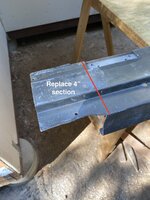
I've also started framing out a commercial steel door I picked up on CL. Unfortunately, the PO mangled one of the jambs to make it fit his building, so I have to figure out a repair. I'm not having any luck finding a spare section of this jamb to weld in, the manufacturer (CECO) doesn't make repair panels which surprises me. I guess it's more cost effective to completely replace a KD frame when you're paying for labor.

Looks like I'll probably have to make the repair panel from scratch.

IMG_1542.JPGF3944548-CCE4-4EBF-8B6F-82E25D625056.jpeg
 
To avoid these ads, REGISTER NOW!
Top Bottom