To avoid these ads, REGISTER NOW!

Ultimate engineers vise design

F-22

Well-known member
Joined
Jan 23, 2022
Messages
1,830
So I was contemplating about the Fireball Hardtail and a few other vise designs. I'm no machinist but I do know a fair bit about most production methods and my cousin even runs a small machine shop making mainly press dies and has a fairly big CNC mill (and I have a mill and a lathe at home as well...).

So I decided to make a nice "ultimate" vise design to maybe eventually make by myself. Something really exceptional, without compromises, that would stay in use long after I am gone. Now we all know there's no real ultimate vise, but I'd like to incorporate design aspects from all historically notable vises. Thought about the top makers I know of and like certain aspects of:
  • Parker - love the outer jaw design, directs and spreads the force onto the support a lot better, smooth transition into the support. The top of the jaws extends far so you can hammer stuff on top of the hardened jaws. Would prefer to simplify the fit to the base a little.
  • Record, Heuer - steel construction. Since I'd be making my own vise on a mill, I'll definitely start off with some steel. Probably some scrap steel I'll search for in the future. Would need at least 350-400mm diameter bar stock to compare to the fireball hardtail (may want to go a bit smaller though? Not sure). If very lucky, I might even get some scrap tool steel though I'd prefer something that isn't hard to machine. I do not want to weld anything. I assume such massive steel construction would give it unparallel strength and ductility among any bench vise, even the old cast steel Record vises (billet steel is basically forged, but would be way more massive than a drop forged Heuer). I like that the Heuer guide can be adjusted for play but hard to incorporate that into the vise.
  • Reed - well, what makes these special? No crazy designs I'd know off, just very tightly made and very massive. New ones have enclosed spindle.
  • Leinen, Gressel, other continental European vises - the dovetail guide is a nice engineering detail and very strong. However, dovetails on lathes and mills also have the wedge to adjust play.
  • Wilton, York - Sleek design, enclosed spindle, circular guide - I feel like the circular guide would be a good option for me. Easier to achieve really good fits in the housing. Very strong in all directions. Pin in the centre of the jaws - Simple and effective means to centre the jaws and keep them centered even if the screws loosen up. I do not like dovetails on jaws, they are very hard to ever remove. I have a York with a thrust bearing that I'd definitely include in this vise too!
  • Orange vise - good inspiration, also all machined... Ideally instead of making the guide a single piece with the moving jaw like on the Wilton vises, I'd make it so that a hollow piston rod would fit inside the moving jaw (piston rod like for hydraulics on excavators...). Either hard chrome coated or just hardened (not sure, would chrome start to flake off? Probably not if the diameter is large enough and tolerances are tight).
  • Fireball Hardtail - enclosed guide, love the vintage knob and handle
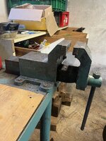
  • System Koch vise - big old German vise I already own is a big inspiration cause it already combines some nice ideas. It's on the photos below. Enclosed spindle, round guide, and I really like the front moving jaw support. The brilliant thing about it is it eliminates the need for the keyway and key that Wilton and York use.
1.jpeg2.jpegIMG_3320.JPEG


I also much prefer the design where the jaws are held on by the screws from the rear side, with threads in the jaws and not screws through the jaws. Keeps the clamping surface uniform and keeps the threads in the replaceable jaws.
Also, if the tube guide is replaceable, I might as well turn in a seat for guide bushings in the fixed housing.


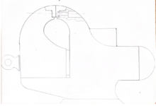
So I did some sketches that I plan to follow to make a CAD model.
Still not quite determined on the size. My Koch has 190mm jaws which is around 7 1/2 inch. I think I definitely do not need a larger vise.

Used the bottom guide idea from the Koch but would love to incorporate a dovetail joint there. Give it rigidity from all sides, besides the main guide, and it would be adjustable like on a lather or a mill. Would need quite exact tolerances with the guide bar though.
33.png22.pngIMG_3325.JPEG11.png

Bar probably shouldn't go in so deep to keep strength in the moving jaw.
All these drawings are just sketches, the focus on design elements is a bit different on each one.

Any further ideas would be very welcome :)
 
Last edited:
To avoid these ads, REGISTER NOW!

tool_scrounge

Well-known member
Joined
Jul 20, 2010
Messages
4,206
Location
Southern California
Dovetail designs are nice from a slop perspective, but they have a stress concentration at the root. So good for finesse work, but not pounding. The Polish FPU vises have that setup, and you see a lot of them on the used market with the front end of the dovetail broken off.
 

gahrajmahal

Well-known member
Joined
Dec 12, 2008
Messages
2,538
Location
Cincinnati, Ohio
Reminds me of my college days in drafting class. Everyone had to draw a vise assembly drawing along with all the detail drawings to make it with. Sectional views of the working screw assembly. Probably helped to make me the engineer that I became.
 
OP
F

F-22

Well-known member
Joined
Jan 23, 2022
Messages
1,830
Dovetail designs are nice from a slop perspective, but they have a stress concentration at the root. So good for finesse work, but not pounding. The Polish FPU vises have that setup, and you see a lot of them on the used market with the front end of the dovetail broken off.
Didn't saw a FPU vise yet, interesting design, inverted dovetail compared to the more classic German designs. Looks like they went that way so they could use a swivel base cause the classic design requires a lot more material underneath to support the front jaw. It does limit the space under the jaws and I assume it probably makes it overall weaker than a Schlegel or a Leinen?
I'll keep in mind that the dovetail can cause notch effects, though by my idea the jaw base would rest on a "V" shaped support and the dovetail would wrap around from the top basically just to take up any extra play/slack. I don't think any notable forces would travel through the connection, tightening the vise would actually take the load off the dovetail and just push straight on top of the V.

If I were starting to build that type vise from scratch (which I know better than, BTW) I'd begin with a large hydraulic cylinder with a hollow ram. It's already precision tolerance, best steel money can buy and weldable.

jack vines
Hah to be fair I'm just drawn to the design, deep down I doubt it'll end up going much further, at least not next year. The ram is what I meant to use but did not know the name. Basically the rod/piston. Not sure if the housing would be useful for what I'm going for.

Reminds me of my college days in drafting class. Everyone had to draw a vise assembly drawing along with all the detail drawings to make it with. Sectional views of the working screw assembly. Probably helped to make me the engineer that I became.
I also drew in college (I think the project through the year was some axle on two bearings with a housing and all the parts to properly fix it and the bearings...). Nowadays usually just quick freehand sketches on cardboard or whatever is nearby (I work at a factory in some very specific field, as a production technology research engineer (for technical ceramics like fuses, very unique requirements so every tooling or automation ends up being very custom to handle the fragile clay shapes)), so it was a bit fun to get behind a table and play with the old stencils and rulers, though as you can see I no longer quite have the patience to make it perfect :)
 

CallumRD1

Well-known member
Joined
Jul 7, 2017
Messages
339
Location
Colorado
I pursued a project similar to this recently. I wanted to make an extremely high precision bench vise that addressed all the quibbles I have with other designs. I ended up milling and turning it out of 1018 mild steel (cylindrical body parts and base), 4140 (jaw towers, annealed), 1045 (anvil, hardened), 304 stainless (lead screw end and handle), and copper (jaws). I only used 4140 for the jaw towers because I was able to get large pieces of it reasonably affordably.

Here are some of the details that I chose to address with this design:

- 5" jaws (Shown with oversized 5.25" soft jaws mounted) and a maximum working capacity of ~12"
- Fully enclosed lead screw in cylindrical slide with internal keyway
- 8 tpi acme lead screw for very high clamping pressure at reasonable levels of applied torque
- Hydraulic piston double lip seal around slide to keep grease in and grit out
- Tight tolerances around slide and keyway so there is no perceptible slop in the dynamic jaw even at near full extension
- Replaceable jaw mounting surfaces machined square after assembly so jaws close perfectly square every time
- Replaceable jaws screwed in from back leaving unblemished working surface, especially useful with soft jaws
- Thrust bearing in dynamic jaw
- Handle on a 19mm (3/4") hex so I can remove the handle to keep it away from my work or use a drill to run the vise open/closed
- Hardened anvil removable for resurfacing
- Swivel base pivots about a 1" central pin extremely smoothly
- Dowel pin holes can lock rotation at any 45˚ increment around the base so no amount of force will rotate the vise on its base
- Vise set as low as possible into base to minimize working height of jaws above bench surface


I wanted the vise to be big and stout with the precision to hold freshly machined parts securely without damaging them. I'm quite sure I'll never push this vise near it's breaking point, but it's overbuilt to allow the precision to be retained even under very high clamping loads. I've used it to perform some extremely tight press fits that must have taken several tons of force and it gave no indication of being anywhere near it's limit.
2022,04,28-CRD_8999.jpg

2022,04,28-CRD_9004.jpg
 

tarbellb

Well-known member
Joined
Apr 17, 2011
Messages
5,765
Location
Oregon
I pursued a project similar to this recently. I wanted to make an extremely high precision bench vise that addressed all the quibbles I have with other designs. I ended up milling and turning it out of 1018 mild steel (cylindrical body parts and base), 4140 (jaw towers, annealed), 1045 (anvil, hardened), 304 stainless (lead screw end and handle), and copper (jaws). I only used 4140 for the jaw towers because I was able to get large pieces of it reasonably affordably.

Here are some of the details that I chose to address with this design:

- 5" jaws (Shown with oversized 5.25" soft jaws mounted) and a maximum working capacity of ~12"
- Fully enclosed lead screw in cylindrical slide with internal keyway
- 8 tpi acme lead screw for very high clamping pressure at reasonable levels of applied torque
- Hydraulic piston double lip seal around slide to keep grease in and grit out
- Tight tolerances around slide and keyway so there is no perceptible slop in the dynamic jaw even at near full extension
- Replaceable jaw mounting surfaces machined square after assembly so jaws close perfectly square every time
- Replaceable jaws screwed in from back leaving unblemished working surface, especially useful with soft jaws
- Thrust bearing in dynamic jaw
- Handle on a 19mm (3/4") hex so I can remove the handle to keep it away from my work or use a drill to run the vise open/closed
- Hardened anvil removable for resurfacing
- Swivel base pivots about a 1" central pin extremely smoothly
- Dowel pin holes can lock rotation at any 45˚ increment around the base so no amount of force will rotate the vise on its base
- Vise set as low as possible into base to minimize working height of jaws above bench surface


I wanted the vise to be big and stout with the precision to hold freshly machined parts securely without damaging them. I'm quite sure I'll never push this vise near it's breaking point, but it's overbuilt to allow the precision to be retained even under very high clamping loads. I've used it to perform some extremely tight press fits that must have taken several tons of force and it gave no indication of being anywhere near it's limit.
2022,04,28-CRD_8999.jpg

2022,04,28-CRD_9004.jpg

This needs way more attention and exposure

!!!!!!!!!!!!!!!!!!!!!!!!!!!!!!!!!!!!!!!!!!!!!!!!!!!!!!!!!!!!!!!!!!!!!!!!!!!!
 

shawhite

Well-known member
Joined
May 28, 2014
Messages
1,519
I pursued a project similar to this recently. I wanted to make an extremely high precision bench vise that addressed all the quibbles I have with other designs. I ended up milling and turning it out of 1018 mild steel (cylindrical body parts and base), 4140 (jaw towers, annealed), 1045 (anvil, hardened), 304 stainless (lead screw end and handle), and copper (jaws). I only used 4140 for the jaw towers because I was able to get large pieces of it reasonably affordably.

Here are some of the details that I chose to address with this design:

- 5" jaws (Shown with oversized 5.25" soft jaws mounted) and a maximum working capacity of ~12"
- Fully enclosed lead screw in cylindrical slide with internal keyway
- 8 tpi acme lead screw for very high clamping pressure at reasonable levels of applied torque
- Hydraulic piston double lip seal around slide to keep grease in and grit out
- Tight tolerances around slide and keyway so there is no perceptible slop in the dynamic jaw even at near full extension
- Replaceable jaw mounting surfaces machined square after assembly so jaws close perfectly square every time
- Replaceable jaws screwed in from back leaving unblemished working surface, especially useful with soft jaws
- Thrust bearing in dynamic jaw
- Handle on a 19mm (3/4") hex so I can remove the handle to keep it away from my work or use a drill to run the vise open/closed
- Hardened anvil removable for resurfacing
- Swivel base pivots about a 1" central pin extremely smoothly
- Dowel pin holes can lock rotation at any 45˚ increment around the base so no amount of force will rotate the vise on its base
- Vise set as low as possible into base to minimize working height of jaws above bench surface


I wanted the vise to be big and stout with the precision to hold freshly machined parts securely without damaging them. I'm quite sure I'll never push this vise near it's breaking point, but it's overbuilt to allow the precision to be retained even under very high clamping loads. I've used it to perform some extremely tight press fits that must have taken several tons of force and it gave no indication of being anywhere near it's limit.
2022,04,28-CRD_8999.jpg

2022,04,28-CRD_9004.jpg
This is awesome. Do you have a pictures from the build.
 
To avoid these ads, REGISTER NOW!
OP
F

F-22

Well-known member
Joined
Jan 23, 2022
Messages
1,830
Well, Callums thread drew mme even more into this project haha.

Forgot to mention a big inspiration is also my grandpas vise. Being from Slovenia, ex-YU, there were many major factories around, from one huge historic nearby mine, to a general huge "machine factory" that made everything from conveyor lines to tractors and big excavators. Anyway, there was lots of scrap steel and I guess under socialism and mostly everything was state-owned, the workers often had some... spare time, even the boss wouldn't mind especially if it made th3 workers happy and they did their work.

Anyway, new apprentices at the factory made vises from scrap steel, and it was possible to buy them (but not by the books...). They were quite cheap, but all steel. It's a wonderful simple vise that's been in the family for a long time and takes a lot of abuse, and being steel, the anvil surface is actually really usable... Looks basic, just a block ,but being machined from all sides the 90 degree angle on the "anvil" is also extremely useful for fabrication work.
However I don't like - sloppy tolerances, angular design, welded-on-base (not a big issue) and welded-on-dynamic-jaw (never was a problem but just does not seem right...). Though I do know the vise was (ab)used a few times with a pipe over the handle so it's probably good enough.

47AFAB58-5A86-4F32-AD46-76D9A8898899.jpeg
 

slowtwitch73

Well-known member
Joined
Apr 18, 2019
Messages
5,876
Location
Hellgate
I find positioning matters to me much more than precision (thank you, thank you), clamping force etc etc. I'd much rather have a run of the mill vise that offered multiple positions to hold the work, that a razzoo piece of eye candy. You see alot of guys getting it done with those MIC rotating vises. Sloppy tolerances have their merits.. they wont bind if something gets wonky.

I leave the precison for milling vises.
 
OP
F

F-22

Well-known member
Joined
Jan 23, 2022
Messages
1,830
I find positioning matters to me much more than precision (thank you, thank you), clamping force etc etc. I'd much rather have a run of the mill vise that offered multiple positions to hold the work, that a razzoo piece of eye candy. You see alot of guys getting it done with those MIC rotating vises. Sloppy tolerances have their merits.. they wont bind if something gets wonky.

I leave the precison for milling vises.
Fair point, and these vise designs have the advantage that the slop is already taken up by the weight of the dynamic jaw.
In the reverse design used by Leinen, Gressel, Schlegel and many other central European manufacturers, it can be very annoying because the rear jaw lifts up on the dovetail and pushes small stuff out of the vise jaws.
 

slowtwitch73

Well-known member
Joined
Apr 18, 2019
Messages
5,876
Location
Hellgate
Some fo those types are adjustable dovetail.. some not. I have two and really like them.. one on a height adjustable mount that is the bees knees.
 
To avoid these ads, REGISTER NOW!
Top Bottom