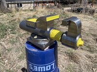
In my shop, I’ve found that my most used tool is my bench vise. I’d long wanted a larger, more precise vise that I could use for everything from holding machined parts right out of the mill for tertiary operations to pressing components together to holding parts for general fabrication. Because I tend to do so much grinding (largely with a 2x72 belt grinder on the same bench as my vise) I’ve long appreciated the sealed construction commonly seen on Wilton bullet vises. I spent a while looking for one that would suit my desires but between the prices in my area and the features of the vise that I wished were done differently, I decided to turn this into a rather ambitious project: building my ultimate bench vise from scratch.
This started as a rather simple list of requirements:
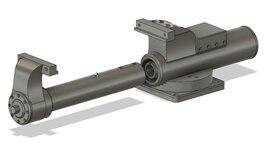
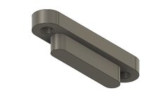
The heart of the design is a fairly simple three-tube constriction, similar (but not identical) to how a Wilton vise is constructed. The outer body tube is 3.5” diameter, 1/2” wall thickness DOM (drawn over mandrill) seamless 1018 steel tubing. The dynamic slide tube is 2.5” diameter, 3/8” wall thickness DOM 1018, and the nut tube is 1-3/4” diameter, 1/4” wall thickness DOM 1018. All had to be turned down slightly to get the appropriate clearance so they telescope properly with minimal but sufficient clearance. Where this design differs substantially from the Wilton design is that I didn’t want an external key/keyway as I wanted an uninterrupted slide tube and I wanted to keep grit out of the keyway. The way I did this was to inset a key into the slide tube that instead of engaging externally on the body tube, rather engaged internally on the nut tube. This means the key and keyway are enclosed inside the sealed part of the vise like the lead screw and nut. This also allowed me to turn a recess in the body tube for a hydraulic double lip seal to keep grit out and grease in.
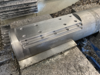
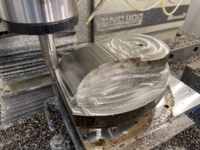
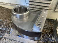
One of the more unique (and I’m sure highly controversial) decisions I made was to secure the static jaw tower to the cylindrical body tube with screws rather than welding it. There were a number of reasons for this, but a big one was that I wanted to avoid the inevitable distortion that would come from welding onto my precision-turned body tube. I milled longitudinal steps into the body tube that were an interference fit to the jaw tower and anvil support block so the tower was keyed into the body tube. This prevented any rotation of the tower under load and allowed for the clamping forces to be translated directly into the body tube. All the screws had to do was keep the jaw tower pulled down to the body tube. I used ten 5/16-18 high strength socket cap screws for this which my quick-and-dirty calculations say should be comfortably overkill for any loads this vise should see.

I used the same stepped construction technique to inset the vise body into the base, reducing the stack height and ensuring that any rotational forces being applied to the vise were being carried by the stepped interface rather than just screws.

The dynamic jaw tower was milled from a single piece of 4140 and shrink-fit onto the slide. I also pressed 8 dowel pins through the dynamic jaw tower into the slide, irrevocably locking them together. These pins were left slightly proud of the surface and ground flush so after paint they’re completely undetectable.

The swivel base is fairly normal with two key features that make an enormous difference in use. First, the vise swivels on a 1” pin with only a couple thou of clearance. This tight tolerance combined with the finely machined (and greased) mating surfaces means that it swivels like it’s on a bearing, very smooth with minimal effort. To counteract the perineal complaint of swivel bases slipping under large loads I decided to drill and ream a pair of 3/8” dowel pin holes in the vise base and put corresponding holes in the swivel base, clocked every 45˚. This allows me to set the vise to any of the eight 45˚ increments and insert the T-handle pins thereby locking the vise to the base so it cannot swivel under any load short of shearing a pair of 3/8” hardened dowel pins! There are of course a pair of normal locking levers to clamp the vise to the base but with the dowel pins inserted these levers only need to prevent lifting of the vise off the base, not prevent rotation of the vise.

As soon as I got the vise painted I put it into service and I couldn’t be happier with it. One of the real joys of designing and making something yourself is that you own the decisions. I chose to implement the features most important to me and appreciate them each time I use the vise. It’s not perfect in any sense of the word, but each mistake, oversight, and blemish is of my hand or a product of my decisions. I fully expect to be using this vise long into the future and I don’t wish for any other.


This was a massive project that took place over about a year, so I just included some highlights of the build in my narrative above. I’m more than happy to delve into the details of any part of the build that you may be interested in.
I don’t expect anyone else to think this was a good idea and worth the time, effort, and money I put into it, but I hope that my work serves to inspire others to tackle a project that they’re passionate about.
Please feel free to ask any questions that you may have; I’ll try to answer them all as best I can.
This started as a rather simple list of requirements:
- 5” jaws with the same screw pattern as my current vise so I could share soft/hard jaws between my vises
- 10”+ maximum capacity for holding large parts
- Sealed slide/screw assembly to keep grit out and grease in
- Thrust bearing in the dynamic jaw for more efficient transfer of applied torque to clamping pressure
- Fine pitch (8 tpi) ACME lead screw for high clamping pressure
- Removable handle with hex on lead screw for operating vise with a drill
- Swivel base with dowel pins locking the vise at 45˚ increments so it can’t swivel unintentionally under high loads
- Hardened and removable (for resurfacing) anvil
The heart of the design is a fairly simple three-tube constriction, similar (but not identical) to how a Wilton vise is constructed. The outer body tube is 3.5” diameter, 1/2” wall thickness DOM (drawn over mandrill) seamless 1018 steel tubing. The dynamic slide tube is 2.5” diameter, 3/8” wall thickness DOM 1018, and the nut tube is 1-3/4” diameter, 1/4” wall thickness DOM 1018. All had to be turned down slightly to get the appropriate clearance so they telescope properly with minimal but sufficient clearance. Where this design differs substantially from the Wilton design is that I didn’t want an external key/keyway as I wanted an uninterrupted slide tube and I wanted to keep grit out of the keyway. The way I did this was to inset a key into the slide tube that instead of engaging externally on the body tube, rather engaged internally on the nut tube. This means the key and keyway are enclosed inside the sealed part of the vise like the lead screw and nut. This also allowed me to turn a recess in the body tube for a hydraulic double lip seal to keep grit out and grease in.
One of the more unique (and I’m sure highly controversial) decisions I made was to secure the static jaw tower to the cylindrical body tube with screws rather than welding it. There were a number of reasons for this, but a big one was that I wanted to avoid the inevitable distortion that would come from welding onto my precision-turned body tube. I milled longitudinal steps into the body tube that were an interference fit to the jaw tower and anvil support block so the tower was keyed into the body tube. This prevented any rotation of the tower under load and allowed for the clamping forces to be translated directly into the body tube. All the screws had to do was keep the jaw tower pulled down to the body tube. I used ten 5/16-18 high strength socket cap screws for this which my quick-and-dirty calculations say should be comfortably overkill for any loads this vise should see.
I used the same stepped construction technique to inset the vise body into the base, reducing the stack height and ensuring that any rotational forces being applied to the vise were being carried by the stepped interface rather than just screws.
The dynamic jaw tower was milled from a single piece of 4140 and shrink-fit onto the slide. I also pressed 8 dowel pins through the dynamic jaw tower into the slide, irrevocably locking them together. These pins were left slightly proud of the surface and ground flush so after paint they’re completely undetectable.
The swivel base is fairly normal with two key features that make an enormous difference in use. First, the vise swivels on a 1” pin with only a couple thou of clearance. This tight tolerance combined with the finely machined (and greased) mating surfaces means that it swivels like it’s on a bearing, very smooth with minimal effort. To counteract the perineal complaint of swivel bases slipping under large loads I decided to drill and ream a pair of 3/8” dowel pin holes in the vise base and put corresponding holes in the swivel base, clocked every 45˚. This allows me to set the vise to any of the eight 45˚ increments and insert the T-handle pins thereby locking the vise to the base so it cannot swivel under any load short of shearing a pair of 3/8” hardened dowel pins! There are of course a pair of normal locking levers to clamp the vise to the base but with the dowel pins inserted these levers only need to prevent lifting of the vise off the base, not prevent rotation of the vise.
As soon as I got the vise painted I put it into service and I couldn’t be happier with it. One of the real joys of designing and making something yourself is that you own the decisions. I chose to implement the features most important to me and appreciate them each time I use the vise. It’s not perfect in any sense of the word, but each mistake, oversight, and blemish is of my hand or a product of my decisions. I fully expect to be using this vise long into the future and I don’t wish for any other.
This was a massive project that took place over about a year, so I just included some highlights of the build in my narrative above. I’m more than happy to delve into the details of any part of the build that you may be interested in.
I don’t expect anyone else to think this was a good idea and worth the time, effort, and money I put into it, but I hope that my work serves to inspire others to tackle a project that they’re passionate about.
Please feel free to ask any questions that you may have; I’ll try to answer them all as best I can.