To avoid these ads, REGISTER NOW!

Tap Handle for Hand Reamers

teagueo

Well-known member
Joined
Mar 7, 2017
Messages
464
What's the preferred handle or socket for using a hand reamer? These are longer, tapered reamers compared to straight ones for use in a mill. I didn't plan on using a drill because I want to carefully remove the material so I don't oversize the holes.

It's a 13mm reamer (a little over 1/2") and would be used to "match drill" 2X holes (like line-boring) so they both align.

I don't have any tap handles for that size and was thinking maybe a socket would work?
 
To avoid these ads, REGISTER NOW!

ecotec

Well-known member
Joined
Oct 5, 2010
Messages
5,451
What's the preferred handle or socket for using a hand reamer? These are longer, tapered reamers compared to straight ones for use in a mill. I didn't plan on using a drill because I want to carefully remove the material so I don't oversize the holes.

It's a 13mm reamer (a little over 1/2") and would be used to "match drill" 2X holes (like line-boring) so they both align.

I don't have any tap handles for that size and was thinking maybe a socket would work?
Take a picture of it.
 

Firebrick43

Well-known member
Joined
May 12, 2015
Messages
14,096
Location
West central Indiana
Lisle makes tap socket that are sized for driving taps/reamers. They are really good for cleaning up previously tapped holes, or continuing tapped holes, they are terrible to start a tap or use a reamer unless its back in a corner that you cant get a traditional handle in.

Starrett 91C is the gold standard if you have the room to swing the handle, especially with taper reamers.


s-l640.jpg
 

johninct

Well-known member
Joined
Dec 21, 2010
Messages
2,596
I am no machinist so I could be all wrong , but if you are trying to ream both holes
 

johninct

Well-known member
Joined
Dec 21, 2010
Messages
2,596
I am no machinist, so I could be all wrong, but if you are trying to ream both holes that need to have the same exact center, it needs to be done on a lathe. If exact same center is not needed, you could ream each hole separately and get good results. Reaming is not drilling and is meant to only take off small amounts of metal. I have used reamers in drill chucks held in my hand with good results.
 
OP
T

teagueo

Well-known member
Joined
Mar 7, 2017
Messages
464
Lisle makes tap socket that are sized for driving taps/reamers. They are really good for cleaning up previously tapped holes, or continuing tapped holes, they are terrible to start a tap or use a reamer unless its back in a corner that you cant get a traditional handle in.

Starrett 91C is the gold standard if you have the room to swing the handle, especially with taper reamers.


s-l640.jpg

I have Starretts for the smaller sizes - love the look and feel of them.

It might be the best bet for keeping in centered compared to a ratchet.

DSC_2874~3.JPG

@johninct That would be ideal to chuck it up in the lathe. But the backside of those holes are angled, so I'd have to custom make a washer to match it when tightening a nut onto it.

It doesn't have to be "perfect" as I will turn the OD of the part in relation to those 2 holes, and there's some excess material there to account for that.

The holes were spec'd at 12.75mm so I could finish ream them to 13mm. But it's 3D printed, and in that print direction (the build axis), it's not very accurate. Oblong holes with 12.4 mm being the minimum diameter.
 

2oolhound

Well-known member
Joined
Dec 18, 2010
Messages
5,918
Location
BC Canada
Hand reamers have a cone that fits into the opposite side of the hole from the side you enter so the front reamer shaft will fit into the hole or inside of the cone and self center as you start cutting at the front on the opposite side. However your wrist pin bore has a step on the outside where diameter of the piston is wider at the top edge of the piston which would prevent a cone from centering. Therefor I'd think you would have to fix the piston down and use chucking reamers to bore the holes.

Here are some videos etc that use a lathe and fixtures to do the work.

https://www.linkedin.com/pulse/a27-...se-article_more-articles_related-content-card

This guy is using an adjustable hand reamer to do the pin bores which should be done using a chuck in the tail stock after drilling.:


This process is beyond my skill set so hopefully others will chime in.

If using a socket to engage a hand reamer use a sliding T drive so you have one hand on each end of the tool to keep it even and balanced like the tap wrench in post #4..
 
To avoid these ads, REGISTER NOW!

fatfillup

Well-known member
Joined
Jan 17, 2009
Messages
10,328
Location
Finksburg, Md
If it has a square end, you can always use a 4 or 8 point socket. If you want it permanent, tack it into the socket
 

RoninB4

Well-known member
Joined
Jul 22, 2020
Messages
3,568
Location
Under My House
This process is beyond my skill set so hopefully others will chime in.
-Not sure where to begin after reading the posts and watching the video. The tolerance(s) required aren't posted, nor is the equipment/machinery involved. I can say that if all you have is a caliper, a worn out lathe (per the video description), and no other measuring equipment then your tolerances better be wide and your expectations low as there's plenty of reasons to expect a seized piston after low running hours.

However, if this is just an experimentation and/or a learning experience then by all means have a go at it. Whether holding a reamer by one hand or two there's multiple reasons to get the axis of the reamer out of alignment with the axis of the holes. Cutting tools need to be rigidly fixed in location to the machine. A chuck in the tailstock of the lathe is no guarantee of alignment either. The leading hole will also likely be larger than the trailing hole as a result. Axis of said holes will likely NOT be perpendicular to axis of piston body. Machining afterwards by using the holes as a reference? Without accurate fixtures (like a good V-block), a surface plate, and indicators it's not likely you'll produce good results to know where and how much to machine off the piston body.

I don't want to discourage you or piss in your corn flakes but you have too many variables, too little equipment, not enough (by your admission) skills, and no previous attempts to form a baseline of info. You may succeed at achieving poor-to-mediocre results. If you're prepared for this and still wish to push on then record EVERYTHING you do to analyze areas for improvement the next attempt.

Good luck and report back if you want further assistance. Ganbatte.
 

matt_i

Well-known member
Joined
Mar 14, 2008
Messages
10,728
Location
SE Michigan
My thought is you want to bore those holes first with a single point tool to correct the alignment and get a basic (under) sized diameter. Then ream for finish and final diameter.

Personally I would want to perform both of those in a mill like a Bridgeport. Long boring tool to be able to reach thru to machine both bosses but keep cuts light and speeds low to avoid chatter.

As above, I think your probability of success is greatest if you fixture this in a machine. Hand operations are iffy at best.

Especially consider that a 13mm reamer probably has an undersized shank, lets just say its 12mm for illustration. Unless I'm wrong about the scale of the part, once the 13mm working/cutting diameter of the reamer exits the first lug then its like the wild west with nothing left of the original hole to pilot the tool. You could try to bandage over that with a top-hat-style bushing which is +.001" over the reamer shank size and -.001" under the finished 13mm diameter to help guide the 2nd hole from the first hole, but the L/D ratio (engaged length divided by diameter...a non-unit measure of how well a bushing can "guide" based on its extra length) I expect would be pretty small. The interaction between the reamer's leading-edge chamfer and the sharp edge of the pilot hole makes a big difference in the final alignment without a spindle-bearing-guide. While it looks smooth it doesn't look like a flat plane to me.

Bottom line, lot of work to try to bandage around a setup which could be done correctly in the machine with a much higher probability of success.
 
OP
T

teagueo

Well-known member
Joined
Mar 7, 2017
Messages
464
-Not sure where to begin after reading the posts and watching the video. The tolerance(s) required aren't posted, nor is the equipment/machinery involved. I can say that if all you have is a caliper, a worn out lathe (per the video description), and no other measuring equipment then your tolerances better be wide and your expectations low as there's plenty of reasons to expect a seized piston after low running hours.

However, if this is just an experimentation and/or a learning experience then by all means have a go at it. Whether holding a reamer by one hand or two there's multiple reasons to get the axis of the reamer out of alignment with the axis of the holes. Cutting tools need to be rigidly fixed in location to the machine. A chuck in the tailstock of the lathe is no guarantee of alignment either. The leading hole will also likely be larger than the trailing hole as a result. Axis of said holes will likely NOT be perpendicular to axis of piston body. Machining afterwards by using the holes as a reference? Without accurate fixtures (like a good V-block), a surface plate, and indicators it's not likely you'll produce good results to know where and how much to machine off the piston body.

I don't want to discourage you or piss in your corn flakes but you have too many variables, too little equipment, not enough (by your admission) skills, and no previous attempts to form a baseline of info. You may succeed at achieving poor-to-mediocre results. If you're prepared for this and still wish to push on then record EVERYTHING you do to analyze areas for improvement the next attempt.

Good luck and report back if you want further assistance. Ganbatte.
This piston is really just for demonstration/experimentation purposes, so as long as the wrist pin bores are nearly perpendicular to the piston OD, that should allow it to function "long enough"...

I do have a small lathe and micrometers, small bore gauges...but I am no machinist, but patient and meticulous enough to creep up on dimensions.

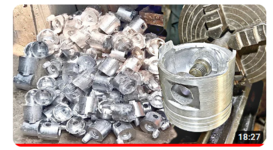
Now I see that the hand reamer doesn't even fit into these very oblong holes, so that bad idea is scrapped. I'll have to start them with an endmill or boring bar to ensure they're not led off center.

My plan is to bore the wrist pins open to size, then indicate on the wrist pin to align it to the lathe cross slide. Then take a skim cut on the bottom of the piston skirt so it serves as a datum for the next fixture.

DSC_2731_2.JPG


Then mount the piston into this fixture and cut the OD of the piston (oversized by 0.5 mm) and cut the ring grooves. For these purposes, the typical elliptical and tapered piston won't be necessary.


Capture.JPG

I'm also considering boring the wrist pin holes as seen in this video by chucking it up on one side. I'd just turn down some stock until is just barely fits into the oblong bores and do one side at a time.


1672632973366.png
 

Attachments

  • 1672632827496.png
    1672632827496.png
    301.2 KB · Views: 5
OP
T

teagueo

Well-known member
Joined
Mar 7, 2017
Messages
464
My thought is you want to bore those holes first with a single point tool to correct the alignment and get a basic (under) sized diameter. Then ream for finish and final diameter.

Personally I would want to perform both of those in a mill like a Bridgeport. Long boring tool to be able to reach thru to machine both bosses but keep cuts light and speeds low to avoid chatter.

As above, I think your probability of success is greatest if you fixture this in a machine. Hand operations are iffy at best.

Especially consider that a 13mm reamer probably has an undersized shank, lets just say its 12mm for illustration. Unless I'm wrong about the scale of the part, once the 13mm working/cutting diameter of the reamer exits the first lug then its like the wild west with nothing left of the original hole to pilot the tool. You could try to bandage over that with a top-hat-style bushing which is +.001" over the reamer shank size and -.001" under the finished 13mm diameter to help guide the 2nd hole from the first hole, but the L/D ratio (engaged length divided by diameter...a non-unit measure of how well a bushing can "guide" based on its extra length) I expect would be pretty small. The interaction between the reamer's leading-edge chamfer and the sharp edge of the pilot hole makes a big difference in the final alignment without a spindle-bearing-guide. While it looks smooth it doesn't look like a flat plane to me.

Bottom line, lot of work to try to bandage around a setup which could be done correctly in the machine with a much higher probability of success.

If I had a Bridgeport, I'd do them something like this:


Just knowing the dimensions here would be easy work for a machinist to locate and align the wrist pin bores, but that would likely exceed the cost of the piston itself...I may try to get a buddy to do it if he has time.

1672633296483.png
 

RoninB4

Well-known member
Joined
Jul 22, 2020
Messages
3,568
Location
Under My House
This piston is really just for demonstration/experimentation purposes, so as long as the wrist pin bores are nearly perpendicular to the piston OD, that should allow it to function "long enough"...
-For demonstration/experimental purposes? It might work and I say "might" with all hesitation I can muster. When you say "nearly perpendicular" I have to wonder how many nearly's is that? Every nearly will lean the piston closer to the cylinder wall so plan accordingly. As for that small lathe you have.....I've done some wacky things with mine when I sold all my industrial grade lathes. Before relying on the accuracy of the cross slide and/or tailstock I'd advise you verify either before employing them. Yes it's a function of the inherent accuracy of the machine as constructed at the factory but I'm telling you that the cross slide is likely not very perpendicular to the headstock axis and the tailstock axis isn't aligned to the headstock axis either. Can you align them with careful gib adjustment? You can certainly improve what the factory left you to with.

That drawing you posted shows the top of the piston being crowned and having relief for the valve faces. This strongly suggests an interference potential with the valve face/edge contacting the piston top when at TDC. If you don't have a milling machine to accurately add that clearance you'll end up with bent valves before the motor even gets fired up. Do you know how to check for clearance with clay and/or plastigage? A CAD program would be of benefit here but not required.

The video methods? I'll give you credit for searching for solutions but bear in mind that the clearance for a truck piston-to-cylinder bore is much greater than a small motorcycle motor. Think of clearance as a percentage of the two diameters and scale that percentage up/down for a given size. With all the variables I've mentioned I would still encourage you to pursue this for educational purposes but would also fully expect you to hear piston slap and skirt scrape as the two surfaces friction weld themselves into a kinetic sculpture of mechanical chaos. Willing to answer further questions you may have in order to fulfill my twisted voyeurism tendencies.

Go for it kid, see what happens. Just be safe and live to tell the tale.
 
Last edited:
OP
T

teagueo

Well-known member
Joined
Mar 7, 2017
Messages
464
@RoninB4 Thanks for the advice!
Yes it's a function of the inherent accuracy of the machine as constructed at the factory but I'm telling you that the cross slide is likely not very perpendicular to the headstock axis and the tailstock axis isn't aligned to the headstock axis either.
This is a good point. Very true for this lathe especially - I probably wouldn't trust the accuracy over longer cuts, but with such short spans to be turned, I'm hoping for the best!

That drawing you posted shows the top of the piston being crowned and having relief for the valve faces. This strongly suggests an interference potential with the valve face/edge contacting the piston top when at TDC.
I planned on checking clearance with playdough. That area did not print extremely well; the valve pockets have some porosity, are slightly shallow and the radii are smaller than designed (possible hot spots). Plus, the piston may be taller than designed.

I'll give you credit for searching for solutions but bear in mind that the clearance for a truck piston-to-cylinder bore is much greater than a small motorcycle motor. Think of clearance as a percentage of the two diameters and scale that percentage up/down for a given size.
The good thing is, I plan on running the piston in the transparent acrylic engine cylinder first before giving it a go in the dirtbike. Acrylic has a much higher coefficient of thermal expansion than aluminum, so the clearances won't be an issue. But in the bike, I may have to run looser piston to wall clearance.

fully expect you to hear piston slap and skirt scrape as the two surfaces friction weld themselves into a kinetic sculpture of mechanical chaos. Willing to answer further questions you may have in order to fulfill my twisted voyeurism tendencies.
Pure poetry brother!
 

RoninB4

Well-known member
Joined
Jul 22, 2020
Messages
3,568
Location
Under My House
The good thing is, I plan on running the piston in the transparent acrylic engine cylinder first before giving it a go in the dirtbike. Acrylic has a much higher coefficient of thermal expansion than aluminum, so the clearances won't be an issue. But in the bike, I may have to run looser piston to wall clearance.
-Ok, you've now "set the hook" in me, I'm intrigued about the outcome. Post results please.
 
To avoid these ads, REGISTER NOW!
Top Bottom