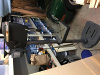
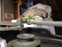
The more I study your pictures and compare them to mine, I'm quite certain you have an incorrect belt(s).


In both pictures, the control arm is set to the slowest speed, which positions the front V-S pulley as far back as it will go.
The front belt on yours is positioned in the middle of the front V-S pulley, whereas mine is at the smallest point of the front V-S pulley.
The middle belt on your V-S is in the middle of both V-S pulleys, whereas mine is at the largest point on the front V-S pulley and the smallest point of the rear V-S pulley. At minimum, your front belt is too long. New belts will solve that issue.