To avoid these ads, REGISTER NOW!

Craftsman Drill Press

OP
F

FrankLee

Well-known member
Joined
Sep 13, 2010
Messages
3,548
Location
seMI, 48317
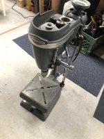
Well, I couldn't control myself...the seller responded a little later than I wanted, but with the requested extra pictures, plus I was able to set up a dinner with a buddy afterwards. So, I bought the Craftsman 100, model 103.24530. More project than I'd really intended, but it was the cheapest 100/150 I could find. Seller demonstrated that the motor spins freely, and quietly, even with the old dry rotted cord.

Started cleaning up the DP yesterday, with nothing significant to report. I'm amazed by how much better the table looks after a little soap and cold water. Working the column over with a grinder and a wire wheel sure left my hands tingling for a bit. Need to find some paste wax to protect the column (it's humid here), then clean the bare metal areas of the (non-angle adjustsable) table and stand. FrankLee was spot-on about the later model base on my DP. Sharp eyes...

The easy to remove parts are off the head.

To do:
- replace the electric cord
- remove the quill
- get an AutoZone belt
- get FrankLee's replacement washer & quill bumper set
- test runout
- disassemble chuck for cleaning. It opens/closes well.
Cosmetics:
- finish cleaning
- strip & paint (?)
- finish getting back to bare metal on table, column and base. Then coat all with paste wax.

Excellent!

My dp#66 is the bench version of yours. I initially thought mine would be a part out but after cleaning the cast iron, I decided it would be a refurb. I highly recommend a degreaser product to clean paint. I use Grez Off. The results are very impressive

Whenever I post a new find, I always update that post with progress on the refurb. Check it out:
https://www.garagejournal.com/forum/showthread.php?p=8090800#post8090800

I’m working on dp#66 and dp#68 simultaneously, so it’s taking a bit longer
 
Last edited:
To avoid these ads, REGISTER NOW!
OP
F

FrankLee

Well-known member
Joined
Sep 13, 2010
Messages
3,548
Location
seMI, 48317
dp#69

DP#69 is another Emerson Craftsman 150 bench model 113.24501. It's dirty, but in very nice shape.


The original 113.19739 motor has a fubar centrifugal switch, but came with an optional on/off switch and a nice foot switch. Two other motors came with the deal.


10/14/2019

So here's the issue with the centrifugal switch. The small nubbin broke off the round piece under the fiber block. The nubbin protruded through the hole in the rectangular piece and peaned for an electrical connection. It is very small and I'm not sure I can repair it.


10/17/2019

 
Last edited:

lafester

Well-known member
Joined
Mar 1, 2017
Messages
2,191
Location
Northern CO
I just brought home a like-new 3rd gen Emerson and it even has the tilt table.
Problem is they lost the bolt holding the tables together...
I looked around and I don't see it in the manual or in any pics so far.
Just curious what they used in case I decide to mount it.

Thanks!
 

Attachments

  • craftsmandp.JPG
    craftsmandp.JPG
    85.9 KB · Views: 33
Last edited:

Agrove27

Well-known member
Joined
Aug 18, 2018
Messages
45
Location
Indiana
so i havent used my restored drill press much but tonight i was using it and thought maybe it was a little noisy so i started investigating sources of noise. firstly it needs to be mounted down to reduce shaking etc. but it still seemed noisiest at the spindle pulley. i checked it for "slop", which there didn't seem to be an excessive amount but i did find that the pulley was able to be moved up and down. is this normal? what can i do to quiet it down some.
 

Attachments

  • 72693215_2299378646833255_3467697440205832192_n.jpg
    72693215_2299378646833255_3467697440205832192_n.jpg
    73.5 KB · Views: 21
  • 72821019_1533851350088104_4080032851741900800_n.jpg
    72821019_1533851350088104_4080032851741900800_n.jpg
    84.3 KB · Views: 18
OP
F

FrankLee

Well-known member
Joined
Sep 13, 2010
Messages
3,548
Location
seMI, 48317
I just brought home a like-new 3rd gen Emerson and it even has the tilt table.
Problem is they lost the bolt holding the tables together...
I looked around and I don't see it in the manual or in any pics so far.
Just curious what they used in case I decide to mount it.

Thanks!

That looks like a very clean machine!

That should be a standard 1/2-13 bolt by roughly 1-1/2" long with a standard washer. There should also be a 1/4" indexing pin.
 
OP
F

FrankLee

Well-known member
Joined
Sep 13, 2010
Messages
3,548
Location
seMI, 48317
so i havent used my restored drill press much but tonight i was using it and thought maybe it was a little noisy so i started investigating sources of noise. firstly it needs to be mounted down to reduce shaking etc. but it still seemed noisiest at the spindle pulley. i checked it for "slop", which there didn't seem to be an excessive amount but i did find that the pulley was able to be moved up and down. is this normal? what can i do to quiet it down some.

Lots going on here... noise, vibration, spindle pulley.

Firstly, no, vertical movement of the spindle pulley is not normal. Several things could be causing that:
  • the spindle retaining screws were not installed
  • the spindle retaining screws are broken
  • the spindle retaining screws were replaced with shorter screws
  • the spindle pulley assembly was not fully seated into the head frame when the retaining screw were installed

Review the Spindle Pulley Assembly post.


Secondly, the feed stop bracket may have slid down the quill allowing the spindle collar to bump up on the spindle pulley.

Review the Quill Snap Ring post.


Address these issues first and report back. They may affect the noise and vibration.
 
OP
F

FrankLee

Well-known member
Joined
Sep 13, 2010
Messages
3,548
Location
seMI, 48317
dp#70

I picked up dp#70 last evening. That cross slide intrigued me. It's a second gen Emerson Craftsman 15-1/2" model 113.24560 and will likely be a parts machine.


10/16/2019

The motor on dp#70 is a Dayton 1/2 hp. It was very nasty dirty, but cleaned up very respectably. I think this will get installed on dp#69.

 
Last edited:

lafester

Well-known member
Joined
Mar 1, 2017
Messages
2,191
Location
Northern CO
That looks like a very clean machine!

That should be a standard 1/2-13 bolt by roughly 1-1/2" long with a standard washer. There should also be a 1/4" indexing pin.

Thanks! Yeah it is pretty clean, barely used. I'll be using this for awhile as my secondary press until I find something better. The bearings sound pretty dry in there so I will pull it apart and see how it looks. For $50 I can't complain. Usually anything in that range is pretty rusty.
 

lafester

Well-known member
Joined
Mar 1, 2017
Messages
2,191
Location
Northern CO
Re: dp#70

That does look interesting! Sure is nice when the accessories are more interesting then the machine.

I picked up dp#70 last evening. That cross slide intrigued me. It's a second gen Emerson Craftsman 15-1/2" model 113.24560 and will likely be a parts machine.


Indexmill

Well-known member
Joined
Apr 12, 2013
Messages
1,413
Location
Central NC
Re: dp#69

DP#69 is another Emerson Craftsman 150 bench model 113.24501. It's dirty, but in very nice shape.

The original 113.19739 motor has a fubar centrifugal switch, but came with an optional on/off switch and a nice foot switch. Two other motors came with the deal.


10/14/2019

So here's the issue with the centrifugal switch. The small nubbin broke off the round piece under the fiber block. The nubbin protruded through the hole in the rectangular piece and peaned for an electrical connection. It is very small and I'm not sure I can repair it.


Sure you can make a new part and fix that Frank! Or one of us can help you do it... Some more pics please of both sides and of a good switch if possible. Surely we can come up with a solution to save an original motor.
 
OP
F

FrankLee

Well-known member
Joined
Sep 13, 2010
Messages
3,548
Location
seMI, 48317
Re: dp#69

Sure you can make a new part and fix that Frank! Or one of us can help you do it... Some more pics please of both sides and of a good switch if possible. Surely we can come up with a solution to save an original motor.

Yeah. I'll have to take another look at it. I think my original assumption was incorrect. It looks like burn marks through the board hole on the round piece.

The original paint on the motor is very nice, so it is well worth pursuing a fix.


The date code on the motor is "E 62". The '63 catalog shows several other similar models. The start switch for most of these models is the same part number on Searspartsdirect.

48902079888_42686b3ef8_c.jpg
 

bsorcs

Member
Joined
Jun 1, 2019
Messages
19
Location
New Orleans
Probably your best bet.

It really should be wired wye if that's what the data plate shows. Wiring delta instead could be the cause of the high current draw (and heat), but the question is why doesn't it run connected wye if that is its design? Bad winding? Mis-numbered winding wires? It is quite puzzling for sure.

Took it to the motor shop. They wired it wye, ran it unloaded, saw <2 amps per leg, ran without issue, so I can skip trying wiring it directly. Got back to my shop and verified the continuities in the extension cord and pigtail to the switch. The problem has to be the switch wiring.

When I wired the switch I assumed that the line legs read left to right [L1, L2, L3] and the load legs right to left. Not certain why I thought this, but it's what I did. I wired L1 to 6, L2 to 3, and L3 to 2, per the switch diagram. Uncertainty lies in the load side wiring. The switch diagram shows what I assumed to be T1 wired to 5, T2 to 1 and T3 to 4. Nosing around I found a discussion of my issue at the following.

https://www.industrial-electronics.com/motor_control/3h_Reversing-Motors-Drum-Switch.html

In this discussion, Figure 3b [attached] shows a three-phase motor connected via a reversing switch such as I have. In essence, this diagram differs from my switch diagram in that it swaps the L2 and L3 destinations, with L2 going to terminal 6...line side terminal farthest from where L1 is connected...instead of terminal 3 on the load side, and L3 going to terminal 3. It also swaps the T1 and T3 connections. This substantial difference further confounds me!

It seems that I have two courses of action. First, determine the continuities in the switch in the forward and reverse positions, then find a reference relative to 3-ph operation to see if the continuities match up. Second, if this yields fruit, re-wire the switch assuming that: both the line and load legs are to be read from right to left on the switch diagram; the line- and load-leg wires should correspond [ie L1 and T1 are black, L2 and T2 red, and L3 and T3 white, since this is the clockwise-from-ground progression I have in the plugs and sockets]; and I should start with L1 to terminal 2.

Once more unto the breach...
 

Attachments

  • Switch wiring diagram.jpg
    Switch wiring diagram.jpg
    91.6 KB · Views: 20
  • industrial electronics.com switch wiring.jpg
    industrial electronics.com switch wiring.jpg
    30.9 KB · Views: 21
OP
F

FrankLee

Well-known member
Joined
Sep 13, 2010
Messages
3,548
Location
seMI, 48317
Re: dp#69

Yeah. I'll have to take another look at it. I think my original assumption was incorrect. It looks like burn marks through the board hole on the round piece.

The original paint on the motor is very nice, so it is well worth pursuing a fix.


Because I really had nothing to lose, I cleaned up the tip of the round piece, both sides of the plate around the hole and soldered them together. It works and is holding so far! I should have taken
in-progress pictures, but wasn't sure this would work.

 
Last edited:

Agrove27

Well-known member
Joined
Aug 18, 2018
Messages
45
Location
Indiana
Lots going on here... noise, vibration, spindle pulley.

Firstly, no, vertical movement of the spindle pulley is not normal. Several things could be causing that:
  • the spindle retaining screws were not installed
  • the spindle retaining screws are broken
  • the spindle retaining screws were replaced with shorter screws
  • the spindle pulley assembly was not fully seated into the head frame when the retaining screw were installed

Review the Spindle Pulley Assembly post.

Secondly, the feed stop bracket may have slid down the quill allowing the spindle collar to bump up on the spindle pulley.

Review the Quill Snap Ring post.


Address these issues first and report back. They may affect the noise and vibration.


ok there were no retaining screws on the spindle pulley, that helped with much of the noise. (also it's currently sitting on a junk little stand so it's not bolted down or anything) while i was messing around i noticed the issue in the picture. when i got the drill it had a copper pin in there so i don't know if thats what should have been there or not but it sheared off. i got it out and just need to replace it. what would you recommend?
 

Attachments

  • 72394043_2360422114222105_3783378816362086400_n.jpg
    72394043_2360422114222105_3783378816362086400_n.jpg
    58.9 KB · Views: 35
OP
F

FrankLee

Well-known member
Joined
Sep 13, 2010
Messages
3,548
Location
seMI, 48317
ok there were no retaining screws on the spindle pulley, that helped with much of the noise. (also it's currently sitting on a junk little stand so it's not bolted down or anything) while i was messing around i noticed the issue in the picture. when i got the drill it had a copper pin in there so i don't know if thats what should have been there or not but it sheared off. i got it out and just need to replace it. what would you recommend?

That's a custom modification that I suspect was to prevent the feed stop bracket from sliding down the quill. A good intention I suppose.

Is your feed stop bracket a closed loop? https://www.garagejournal.com/forum/showthread.php?p=7927673&highlight=closed+loop#post7927673

Recently, I started using a low-strength thread locker when installing the feed stop bracket onto quills with no snap ring. I don't have any long term results from that though.
 
Last edited:

Agrove27

Well-known member
Joined
Aug 18, 2018
Messages
45
Location
Indiana
That's a custom modification that I suspect was to prevent the feed stop bracket from sliding down the quill. A good intention I suppose.

Is your feed stop bracket a closed loop? https://www.garagejournal.com/forum/showthread.php?p=7927673&highlight=closed+loop#post7927673

Recently, I started using a low-strength thread locker when installing the feed stop bracket onto quills with no snap ring. I don't have any long term results from that though.


mine is not the closed loop, i guess i just need to put some threadlocker and tighten it down properly and not let the quill snap back full force
 

Indexmill

Well-known member
Joined
Apr 12, 2013
Messages
1,413
Location
Central NC
Re: dp#69

Because I really had nothing to lose, I cleaned up the tip of the round piece, both sides of the plate around the hole and soldered them together. It works and is holding so far! I should have taken
in-progress pictures, but wasn't sure this would work.


Awesome! That is a beautiful motor.
 

CrotalusAtrox

Well-known member
Joined
Mar 5, 2016
Messages
796
Location
The Great Southwest
Here is a little gem I found came with the slow speed pulley also. It cleaned up really nice
 

Attachments

  • 4C2B7A0C-1CAA-4671-9977-EE89560ACB0C.jpg
    4C2B7A0C-1CAA-4671-9977-EE89560ACB0C.jpg
    61.2 KB · Views: 47
  • 8EA84279-01E0-4D17-B147-D46AC80D6068.jpg
    8EA84279-01E0-4D17-B147-D46AC80D6068.jpg
    105.8 KB · Views: 47
  • C1898063-8120-4659-9463-F347A9BD11F9.jpg
    C1898063-8120-4659-9463-F347A9BD11F9.jpg
    150.2 KB · Views: 49
  • 743925EB-CCC1-4A5F-9BDB-DC067A8A26C6.jpg
    743925EB-CCC1-4A5F-9BDB-DC067A8A26C6.jpg
    99.4 KB · Views: 43
To avoid these ads, REGISTER NOW!

GreyEyes

Well-known member
Joined
Mar 25, 2019
Messages
54
Location
Florida
Took it to the motor shop. They wired it wye, ran it unloaded, saw <2 amps per leg, ran without issue, so I can skip trying wiring it directly. Got back to my shop and verified the continuities in the extension cord and pigtail to the switch. The problem has to be the switch wiring.

When I wired the switch I assumed that the line legs read left to right [L1, L2, L3] and the load legs right to left. Not certain why I thought this, but it's what I did. I wired L1 to 6, L2 to 3, and L3 to 2, per the switch diagram. Uncertainty lies in the load side wiring. The switch diagram shows what I assumed to be T1 wired to 5, T2 to 1 and T3 to 4. Nosing around I found a discussion of my issue at the following.

https://www.industrial-electronics.com/motor_control/3h_Reversing-Motors-Drum-Switch.html

In this discussion, Figure 3b [attached] shows a three-phase motor connected via a reversing switch such as I have. In essence, this diagram differs from my switch diagram in that it swaps the L2 and L3 destinations, with L2 going to terminal 6...line side terminal farthest from where L1 is connected...instead of terminal 3 on the load side, and L3 going to terminal 3. It also swaps the T1 and T3 connections. This substantial difference further confounds me!

It seems that I have two courses of action. First, determine the continuities in the switch in the forward and reverse positions, then find a reference relative to 3-ph operation to see if the continuities match up. Second, if this yields fruit, re-wire the switch assuming that: both the line and load legs are to be read from right to left on the switch diagram; the line- and load-leg wires should correspond [ie L1 and T1 are black, L2 and T2 red, and L3 and T3 white, since this is the clockwise-from-ground progression I have in the plugs and sockets]; and I should start with L1 to terminal 2.

Once more unto the breach...

You are over thinking it.

It's not important which leg is L1, L2 or L3. You just need 2 line legs on top and bottom connections on one side of the switch and the other leg on the center connection on the other side of the switch. The 3 load legs go to the other 3 terminals in any order. If the motor rotation is wrong direction, just switch any 2 load legs with each other. I suspect you had an error in the switch wiring at first. On the picture you posted of the switch, the wiring appeared correct, but I believe that was after you had switched the motor wiring to delta. With the switch wired that way and the motor wye you should be good.
 

JZiggy

Well-known member
Joined
Dec 1, 2014
Messages
990
Location
Atlanta
FrankLee, it's great to see that you still have so much momentum on Craftsman drill presses. This thread has reached the status of "technical library" in my estimation :)
 
OP
F

FrankLee

Well-known member
Joined
Sep 13, 2010
Messages
3,548
Location
seMI, 48317
FrankLee, it's great to see that you still have so much momentum on Craftsman drill presses. This thread has reached the status of "technical library" in my estimation :)

Thanks JZ! "Momentum" is one word for it. LoL!

I figure if learned information is not shared, what's the point. I appreciate everyone's discoveries, participation and posts.
 

IdahoMan

Well-known member
Joined
Feb 26, 2015
Messages
434
I just brought home a like-new 3rd gen Emerson and it even has the tilt table.
Problem is they lost the bolt holding the tables together...
I looked around and I don't see it in the manual or in any pics so far.
Just curious what they used in case I decide to mount it.

Thanks!

That's the model I have, CraftsMan 1969. But I am missing the gear cover.

I'll probably make a gear cover for it out of wood and try to color match the paint via Sherwin Williams.
 

bsorcs

Member
Joined
Jun 1, 2019
Messages
19
Location
New Orleans
You are over thinking it.

It's not important which leg is L1, L2 or L3. You just need 2 line legs on top and bottom connections on one side of the switch and the other leg on the center connection on the other side of the switch. The 3 load legs go to the other 3 terminals in any order. If the motor rotation is wrong direction, just switch any 2 load legs with each other. I suspect you had an error in the switch wiring at first. On the picture you posted of the switch, the wiring appeared correct, but I believe that was after you had switched the motor wiring to delta. With the switch wired that way and the motor wye you should be good.

You are correct. My problem was not recognizing the requisite distribution of the line legs. Once I got that right everything was good except for the direction of rotation, and, the load legs were uniformly at 1.6a. I'll swap two to fix the rotation, but I am intrigued by your statement that the load legs can attach in any order. I am guessing that is due to the presence of 208v between each pair of legs?

A thousand thanks.
 

GreyEyes

Well-known member
Joined
Mar 25, 2019
Messages
54
Location
Florida
I am guessing that is due to the presence of 208v between each pair of legs?

A thousand thanks.

Exactly. Changing the legs only changes the relationship of the phases to each other, that is why the direction is reversed. That is all the drum switch does, switches two legs with each other.

Glad you got it working!
:thumbup:
 
OP
F

FrankLee

Well-known member
Joined
Sep 13, 2010
Messages
3,548
Location
seMI, 48317
dp#71, Delta 28-100, 10" Band Saw

Today's finds...

DP#71 is a Dunlap 12-1/4" drill press model 103.23622.


The 10" Delta band saw is a model 28-100. I really wanted the lamp, but the saw may be decent once cleaned up.


10/24/2019

The refurb of the motor from dp#71 is complete.


10/31/2019

The refurb of dp#71 is complete.

 
Last edited:

Craptain

Well-known member
Joined
Apr 18, 2013
Messages
4,027
Location
Tampa Bay FL
Re: The Classic Craftsman 100/150 Drill Press

I love the extended table on the bandsaw. Yes, the bandsaw will clean up well.

Sent from my SM-G930T using Tapatalk
 

lafester

Well-known member
Joined
Mar 1, 2017
Messages
2,191
Location
Northern CO
That's the model I have, CraftsMan 1969. But I am missing the gear cover.

I'll probably make a gear cover for it out of wood and try to color match the paint via Sherwin Williams.

I think FrankLee has parted a few of these... maybe he has one, or if not I'm sure one will come along at some point.

I got mine cleaned up, oiled up and it purrs nicely now. I'll probably swap out the craftsman chuck with a jacobs since all my other chucks use the same key. Otherwise I'm sure its fine for most anything this press would be doing.
 

ClappedOutBport

Well-known member
Joined
Mar 30, 2016
Messages
998
Re: dp#71, Delta 28-100, 10" Band Saw

Today's finds...

DP#71 is a Dunlap 12-1/4" drill press model 103.23622.


The 10" Delta band saw is a model 28-100. I really wanted the lamp, but the saw may be decent once cleaned up.


I have that exact saw. Don't discount it, it's actually a pretty nice saw. It's got a pretty rigid cast iron frame. The bearings are plain brass/bronze, and the blades are wicked hard to find though. I clearcoated the fiberglass which helped a lot as it was shedding, but the gasket around the edges got super sticky. Tape it off if you go that route.
 

GreyEyes

Well-known member
Joined
Mar 25, 2019
Messages
54
Location
Florida
Re: dp#71, Delta 28-100, 10" Band Saw

Today's finds...

The 10" Delta band saw is a model 28-100. I really wanted the lamp, but the saw may be decent once cleaned up.


Somewhere I think there is a waffle house that's missing a table :)
 
OP
F

FrankLee

Well-known member
Joined
Sep 13, 2010
Messages
3,548
Location
seMI, 48317
Re: dp#71, Delta 28-100, 10" Band Saw, Delta 31-200, 8-1/2" Disk Sander

Somewhere I think there is a waffle house that's missing a table :)

I think you're right!


I picked up this gem today. A nice Delta 31-200 disk sander with a very nice Craftsman 1/2 hp motor and switch accessory. The miter guide is missing.


I already have it cleaned and tweaked.


It was a very good weekend!
 
Last edited:

GreyEyes

Well-known member
Joined
Mar 25, 2019
Messages
54
Location
Florida
That disk sander cleaned up really well!

I would think about saving that Craftsman motor for a needy drill press and keep an eye out for a TEFC one. Doesn't take long for an open motor to get packed with sawdust on a sander.
 

sheltonfilms

Well-known member
Joined
May 28, 2014
Messages
157
Re: The Classic Craftsman 100/150 Drill Press

I’ve got the same Delta disc sander. Use it all the time.


Sent from my iPhone using Tapatalk
 
OP
F

FrankLee

Well-known member
Joined
Sep 13, 2010
Messages
3,548
Location
seMI, 48317
Re: The Classic Craftsman 100/150 Drill Press

That disk sander cleaned up really well!

I would think about saving that Craftsman motor for a needy drill press and keep an eye out for a TEFC one. Doesn't take long for an open motor to get packed with sawdust on a sander.

Yes, it did.

The motor is what I really wanted. The sander is very nice and the switch is a bonus. Yeah, I still have to clean the sawdust out of the motor.

The price was unbelievable! I gave him 120% of his asking price.


I’ve got the same Delta disc sander. Use it all the time.

How is yours set up? I'd prefer the motor below.
 
Last edited:

bubinga

Well-known member
Joined
Jul 26, 2014
Messages
12,744
Location
Bridgeport Ohio. (Across River From Wheeling WV)
Re: The Classic Craftsman 100/150 Drill Press

Yes, it did.

The motor is what I really wanted. The sander is very nice and the switch is a bonus. Yeah, I still have to clean the sawdust out of the motor.

The price was unbelievable! I gave him 120% of his asking price.


How is yours set up? I'd prefer the motor below.
You need to get lucky, and find you an old OEM delta stand.
 
To avoid these ads, REGISTER NOW!
Top Bottom