To avoid these ads, REGISTER NOW!

Cooler Kart Build

aka Larry

Well-known member
Joined
May 2, 2012
Messages
8,011
Location
Eastern, NC
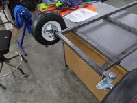
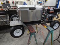
After seeing one of these over 10 years ago, I decided I wanted to build one, well, just because. I can use it to get around the paddock at Lemons races, HPDE's etc.

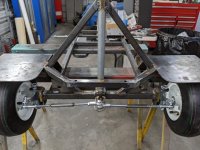
I've had the basic drawing together for years, and have tweaked it many times as more data was acquired. The problem is a lot of the components don't have exact measurements. This thing HAS to be able to fit on my trailer sideways, so the overall length dimension of 48" cannot be exceeded. If I can't make that size, it would be useless. This is the basic drawing, which doesn't have a lot details because a lot of it will have to be figured as I go. Most notably absent is the steering, which will be a challenge because the upper portion will have to be attached to the cooler itself in some fashion.

Basic drawing:

attachment.php


The power plant will be a 6.5HP (212cc) Predator from HF w/ centrifugal clutch, and one wheel drive...simple. The steering will be a T-type handle bar in favor of an actual wheel. Again, this is for simplicity, as I will be able to use a 4-wheeler type thumb and handle brake lever mounted on the bar. The brake will be a simple band/drum type which is mounted to the drive sprocket. I will probably leave the engine's governor for now, but it should still run about 20 MPH or so.
 

Attachments

  • cooler kart frame.jpg
    cooler kart frame.jpg
    107.8 KB · Views: 4,142
To avoid these ads, REGISTER NOW!
OP
A

aka Larry

Well-known member
Joined
May 2, 2012
Messages
8,011
Location
Eastern, NC
Onto the build!

First up was the wheels and tires. I started out thinking I'd use the el-cheapo wheel, tire, hub combo from HF, which are less than $10 each. I joined a go-kart forum and was immediately warned away from using the HF stuff stating it was not built for high-speed use. I don't consider 20 MPH "high-speed", but that term is relative I guess since the HF wheels are made for hand trucks, carts, etc, walking speed type stuff.

With that information, I decided on 5" split wheels, with separate grease-able hubs, and 11"x4.00-5 smooth tires. I wanted "smooth" tires because they look like a "slick", but don't have their short life or cost. The cheapest smooth tires I could find were from TSC for about $7.00 each so I bought those.

For some reason stupid me thought a split rim (uses a tube) would be a piece of cake for installing the tire. I used dish soap on the tire, and assumed it would just slide right in, but trying with all my might that SOB just wouldn't go in the tire. I watched a YouTube video and the guy just dropped his wheel halves right into place. So thinking it might be the tire, I went to TSC and tried my wheel on a couple of different tires of the same size, and still no dice.

I finally decided that I'd either destroy the tire, the wheel, maybe both, but one way or another, that tire was going on that wheel. You know sometimes you just get the mind set of "this thing is not going to beat me!"? I don't don't have a tire machine, but I do have an my HF hydraulic press, so I decided to make a jig and see what would happen. Using some 3/4" plywood, I cut a donut that was sized to fit the wheel and tire, and then added a pair of 2x4s to the bottom as seen here:


attachment.php


Next, I cut a wooden disc sized to fit the center of the wheel and put the entire assembly in the press like so:


attachment.php


I used dish soap on the beads and was able to press one half of the wheel into the tire. Then I was able to fish the tube in the assembles half, and bolt the halves together, leaving just the opposite bead to seat. I'll admit I was nervous about just how much air pressure it would take, especially with my hands right next to the source of the potential shrapnel. Fortunately, I was pleasantly surprised at how easy the opposite bead seated.

As with most anything new, once you do it the first time, the next time goes much quicker so the remaining three went together a lot faster and I ended up with these:


attachment.php
 

Attachments

  • 01-Wheel Jig.jpg
    01-Wheel Jig.jpg
    151.8 KB · Views: 3,735
  • 02-Wheel Jig.jpg
    02-Wheel Jig.jpg
    152.3 KB · Views: 3,648
  • 03-Wheel Assemblies.jpg
    03-Wheel Assemblies.jpg
    151.1 KB · Views: 3,610
OP
A

aka Larry

Well-known member
Joined
May 2, 2012
Messages
8,011
Location
Eastern, NC
With the wheels and tires together, I was finally able to get started on the frame yesterday. I started by sizing the main frame rail's spacing, by using the cooler itself as a guide. Once I had that measurement, I used my band saw to cut the side rails, lower supports, rear bumper, and the front axle.

I decided to hit the easy button and just buy the spindles pre-made from BMI. Probably not necessary, but I decided to set the spindles with 5 degrees of caster before tack welding them to the front axle.

Here's where I am in the build right now...


attachment.php


attachment.php
 

Attachments

  • 04-Frame.jpg
    04-Frame.jpg
    148.7 KB · Views: 3,565
  • 05-Frame.jpg
    05-Frame.jpg
    151.2 KB · Views: 3,557
OP
A

aka Larry

Well-known member
Joined
May 2, 2012
Messages
8,011
Location
Eastern, NC
Finally got back on this project Saturday afternoon.

I'm not used to designing as a I go, which makes it a slow-go for me. Lots of measuring, fit-up, re-measuring, re-fit up, etc. This was especially true with the rear axle because the stubs are different lengths due to the drive wheel.

Once I finally figured out the rear axle length, I had to weld the stubs (5/8" bolts) to each end of the 1" tubing. To keep it square, I made a quick jig with some angle and a few clamps as seen here:

attachment.php


Then I tacked the rear axle to the rear of the frame...

attachment.php


Fortunately the bolt pattern for almost all small engines is the same. I could have made my own engine mounting plate with my plasma cutter, but I would needed to fab a special jig for the slots. I decided that it was not worth my time when I could purchase a pre-made laser-cut plate on-line for $7.95. The plate needed to be raised for access to the bolts, so I tacked it to a pair of 3/4" square tubes.

attachment.php


Engine plate tacked in place on the frame:

attachment.php


Engine mock up to be sure the drive sprockets are properly aligned:


attachment.php


I stopped at the point on Saturday feeling like I had made decent progress.
 

Attachments

  • 10-engine_test.jpg
    10-engine_test.jpg
    152.2 KB · Views: 3,516
  • 09-rear_mock-up.jpg
    09-rear_mock-up.jpg
    149.4 KB · Views: 3,514
  • 08-engine_plate.jpg
    08-engine_plate.jpg
    146.6 KB · Views: 3,513
  • 07-rear_axle.jpg
    07-rear_axle.jpg
    150.7 KB · Views: 3,527
  • 06-axle_stub.jpg
    06-axle_stub.jpg
    131.7 KB · Views: 3,534
OP
A

aka Larry

Well-known member
Joined
May 2, 2012
Messages
8,011
Location
Eastern, NC
Sunday I was feeling good knowing the progress I made on Saturday, and I had pretty much all day to work.

I had already fabricated the side pods where my feet were supposed to rest, so I wanted to check their placement. The first thing I did was to sit the cooler in place to check my seating position. As soon as I sat down I noticed my feet were waaaay too far forward, meaning the rear axle, engine mount, and cooler supports would need to be moved backwards. :( 
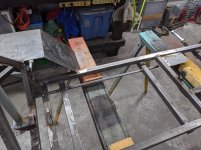
Of course that meant that almost all the work I did on Saturday would need to be redone...dammit!

I started by cutting all the tacks loose, so I could move everything back 2". This meant I had to re-align the axle, engine mount, drive sprockets etc all over again. Once I had everything re-positioned, I rolled the frame outside to be sure it would positively fit on my trailer, which fortunately it did with a little room to spare.

Once all the above was done, I placed the cooler back on the frame for another rider fitment. The problem was I couldn't move everything back as far as I'd like due to the length restriction imposed by my trailer. Therefore the side pods for the foot rest just ain't happening.

In my normal seating position, my feet sit right on top of the front tires. No way around that fact, so what to do? Hold my feet up in the air while I drive? No. Place foot pegs behind me like a motorcycle? No. Even though I hadn't planned on having fenders, that seemed like my only option for a place to rest my feet, so I proceeded down that path.

I started by using my plasma cutter to cut a 8" wide strip of 1/8" steel plate. I then cut that plate into a 16" length and bent it in half at a 45 degree angle. I then notched it to fit the frame. It didn't have enough structure as is, so built a strut with some 3/4" square tube and tacked it in place as seen here on the right:


attachment.php


Side view showing the fender, cooler, and engine mock-up:


attachment.php


I plan to dress the fender up with some rounded corners, and possibly some trim. I'm also going to add some expanded metal onto to the fenders for grip.

Stay tuned....
 

Attachments

  • 11-fender front.jpg
    11-fender front.jpg
    151.9 KB · Views: 3,440
  • 13-side_mock-up.jpg
    13-side_mock-up.jpg
    154.7 KB · Views: 3,458

gearhead1960

ALLIANCE MEMBER
Joined
Mar 21, 2019
Messages
1,799
Location
Manassas, VA, a small blot in history
Larry,

Cool build going on here.

If the foot position won't work as designed, why not rotate the cooler 90 degrees? You would then be able to position your feet closer, sort of like riding a bike vs. a horse. By rotating the cooler, it would position it over your planned foot position that no longer was working anyway....
 
OP
A

aka Larry

Well-known member
Joined
May 2, 2012
Messages
8,011
Location
Eastern, NC
If the foot position won't work as designed, why not rotate the cooler 90 degrees? You would then be able to position your feet closer, sort of like riding a bike vs. a horse. By rotating the cooler, it would position it over your planned foot position that no longer was working anyway....

I actually considered it, and tried it, but for two reasons I decided not to.

1) The entire frame would need to be redone
2) I didn't like the look of it positioned sideways.
 

gungatim

Well-known member
Joined
Jan 8, 2013
Messages
8,101
Location
west mich
looks cool. only advice I can give having built a few carts and mini-bikes from scratch is ditch that (what appears to be a) cheap comet clutch and get a more expensive clutch like they use for kart racing. the HF motor puts out a lot of power and it's not hard to get that clutch red hot. trust me, the one thing worth putting money into out of everything on there is the clutch, especially if you're not going to fit a jackshaft setup.
 
OP
A

aka Larry

Well-known member
Joined
May 2, 2012
Messages
8,011
Location
Eastern, NC
looks cool. only advice I can give having built a few carts and mini-bikes from scratch is ditch that (what appears to be a) cheap comet clutch and get a more expensive clutch like they use for kart racing. the HF motor puts out a lot of power and it's not hard to get that clutch red hot. trust me, the one thing worth putting money into out of everything on there is the clutch, especially if you're not going to fit a jackshaft setup.

This is the clutch I bought. Budget has been a factor in this build, and I'll admit I'm already over budget.

Do you have a specific one in mind? The "racing" clutches I saw are like $150 each!
 

larry4406

Well-known member
Joined
Jan 27, 2006
Messages
19,005
Location
Northern Virginia
Way Cool!

I'm in for the build! The front fenders look like perfect places to rest your feet. Brake pedal left, go peddle right!

Yes the "beverage" holder is a must.
 
To avoid these ads, REGISTER NOW!

shortykorte

Well-known member
Joined
Sep 1, 2014
Messages
8,034
Location
Tallahassee, Fl
This is looking better than those plastic cooler carts.
Following along.


Shorty Korte
Always remember quality in QST

Sent from my iPhone using Garage Journal
 

gungatim

Well-known member
Joined
Jan 8, 2013
Messages
8,101
Location
west mich
This is the clutch I bought. Budget has been a factor in this build, and I'll admit I'm already over budget.

Do you have a specific one in mind? The "racing" clutches I saw are like $150 each!

if you're on a budget stick with what you've got. you'll want to go easy on it for sure, you can always upgrade later.

what gear ratio are you running? sprocket tooth on the clutch and tooth count on the axle? what size diameter are the tires? I can run the #'s and see what you should be running, you don't want to doo too much speed or you'll toast the clutch from a stop, gear it right and you can pop a wheely but keep the speed down to around 20mph or so.

they can be crazy dangerous...last one I did I used a 2 stroke Tecumseh for higher rpm's but less torque, so it was a better ride. Those predator motors can make a serious machine, I could do 45 easy with one I built with the blue HF motor even with the governor intact, but like I said, the clutch was glowing, lol. (not to mention steering and death wobble is scary over 30mph)
 
OP
A

aka Larry

Well-known member
Joined
May 2, 2012
Messages
8,011
Location
Eastern, NC
if you're on a budget stick with what you've got. you'll want to go easy on it for sure, you can always upgrade later.

what gear ratio are you running? sprocket tooth on the clutch and tooth count on the axle? what size diameter are the tires? I can run the #'s and see what you should be running, you don't want to do too much speed or you'll toast the clutch from a stop, gear it right and you can pop a wheelie but keep the speed down to around 20mph or so.

Clutch is 12T and the drive sprocket is 60T. Tire diameter is 11".

Is this good "middle of the road" combination in your opinion? I need more torque than speed due to the weight of the kart, cooler contents, and rider.

I've decided to leave the governor so I want have the urge to go fast enough to due something stupid. ;)
 

gungatim

Well-known member
Joined
Jan 8, 2013
Messages
8,101
Location
west mich
That ratio should work find. at 3600 rpm, your top speed is 23.6 mph. plenty fast. if you take off the governor, you'll just over rev the motor unless you upgrade the valve springs, and want to make 8-10hp, which is pointless.

you'll have to try it out and see if it pulls you from a stop without burning the clutch, it should, that's about the ratio I use except i'll drop to an 11 on the motor depending on how heavy it ends up and how well that clutch sticks.
 
OP
A

aka Larry

Well-known member
Joined
May 2, 2012
Messages
8,011
Location
Eastern, NC
you'll have to try it out and see if it pulls you from a stop without burning the clutch, it should, that's about the ratio I use except i'll drop to an 11 on the motor depending on how heavy it ends up and how well that clutch sticks.

I'm anxious to get to the point when I can find out and report back.

Stay tuned!
 

rattle_snake

Well-known member
Joined
Jun 25, 2015
Messages
5,145
Location
Chandler, AZ
This project is a perfect candidate for a nitrous system. Sneak Pete or similar motorcycle kit, with a tiny jet. Not only would it look cool, but would also help blow out the budget.
 

rmack898

Well-known member
Joined
Jan 23, 2007
Messages
3,142
Location
Honu Grove NE Florida
I'm in for following along on this build, it may give me motivation to finish the bar stool that I started many years ago.

Nice job Larry, keep going.
 
OP
A

aka Larry

Well-known member
Joined
May 2, 2012
Messages
8,011
Location
Eastern, NC
Update from this weekends progress.

I started by finishing up the right side fender. Once that was in place I was able to attach the front bumper as seen here:

attachment.php


Next I added a pair of gussets to support the fender struts and to house the front LED parking lights:

attachment.php


Since the bumper was in place, I went ahead and made provisions for mounting the LED headlight. Since I know how much Mike loves light bars, and had to sit it in place before taking the pic. :bounce:

attachment.php


I finally got around to fitment of the brake band and welded the pin in place that attaches it to the frame. Also I added a mounting plate for the battery holder as seen in the upper left of the pic.


attachment.php


The biggest progress was I finally made some headway on the steering. My initial plan was to use 3/4" EMT and weld up simple T-style handlebars. As it turned out, almost all handlebar mounted controls (brake levers, switches, etc) are sized for 22mm handlebars, and 3/4" EMT is too large for any of those to fit. I ended up ordering set of bars from Amazon and they arrived Sunday around lunch so I was able to get started.

The steering column is made from 3/4" EMT with a 1/2" brass bushing in each end. The actual steering rod is 1/2" dia rod that is welded to the handlebars and slides through the brass bushings. There will be a pitman arm on the bottom end that connects to the tie-rods, but it's not done yet because the tie-rods I purchased are too long. I'll have to modify those, but for now here's where it sits currently:

attachment.php
 

Attachments

  • 18_steering column.jpg
    18_steering column.jpg
    157.3 KB · Views: 2,126
  • 17_brake_pin.jpg
    17_brake_pin.jpg
    150.5 KB · Views: 2,118
  • 16_front_parking_light.jpg
    16_front_parking_light.jpg
    138 KB · Views: 2,113
  • 15_gussets_headlight.jpg
    15_gussets_headlight.jpg
    152.6 KB · Views: 2,118
  • 14_front_bumper.jpg
    14_front_bumper.jpg
    151.3 KB · Views: 2,114

casmurbax

Well-known member
Joined
Sep 25, 2012
Messages
2,756
Location
Wilton, NY
So is this proto-type?

When you start manufacturing these, what will the cost be?

I agree with zmotorsports, looks fast.
 
OP
A

aka Larry

Well-known member
Joined
May 2, 2012
Messages
8,011
Location
Eastern, NC
So is this proto-type?

When you start manufacturing these, what will the cost be?

I agree with zmotorsports, looks fast.

This is a one-off for sure. I'm embarrassed to say how much money I've invested into it already. :shocking: If you're really curious, shoot me a PM with your e-mail address and I'll send you a copy of my spreadsheet.
 

casmurbax

Well-known member
Joined
Sep 25, 2012
Messages
2,756
Location
Wilton, NY
aka Larry, I could just imagine the expense then add the labor to it.

I can't wait to see your video when you first drive it.

Please please make sure the recording of the video captures where you say, "here hold my beer"
 

Bigblockyeti

Banned
Joined
Feb 1, 2018
Messages
2,550
Location
Upstate, SC
Oh man, I'm definitely subbed to this! I need to build my boys something that's small (as well as slow when needed) and beefy enough for me with a seat that can go up for more leg room vs. having to make it longer. This is basically what I had in mind. I have a 5.5hp 2-stroke Tecumseh waiting to be employed and I know where I can get more should it grenade in the future.
 

Slednut

Well-known member
Joined
Dec 20, 2012
Messages
2,550
Location
Washington state
That is cool, learning about kingpin axis, caster and camber can really make these types of projects steer a lot better. This is a child's trikes steering setup I made years ago, I welded it with an oxy Acetylene torch.
 

Attachments

  • Small Trike 6.JPG
    Small Trike 6.JPG
    109.7 KB · Views: 342

zmotorsports

ALLIANCE MEMBER
Joined
Oct 20, 2009
Messages
21,312
Location
Northern Utah
That is cool, learning about kingpin axis, caster and camber can really make these types of projects steer a lot better. This is a child's trikes steering setup I made years ago, I welded it with an oxy Acetylene torch.

Agreed. When I built my son's go-kart I did a lot of homework and made sure to have the proper Ackermann angle, kingpin inclination angle as well as caster/camber and it was a joy to drive and handled like it was on rails.
 

Bigblue&Goldie

Well-known member
Joined
Mar 12, 2009
Messages
10,664
Location
AZ
Agreed. When I built my son's go-kart I did a lot of homework and made sure to have the proper Ackermann angle, kingpin inclination angle as well as caster/camber and it was a joy to drive and handled like it was on rails.

Dust off the old Polaroid's and give us a retro build write up!
 
OP
A

aka Larry

Well-known member
Joined
May 2, 2012
Messages
8,011
Location
Eastern, NC
Sunday afternoon I had a chance to spend a little more time on this project.

The main focus at this point was on the steering. The generic tie-rods I bought were too long, so I had to remove a section in the middle, sleeve it, and weld it back together. Once that was done I welded the pitman arm to the steering shaft and mocked it all up as seen here:


attachment.php


Planning ahead, I added a 1/2 tube through the frame to act as a conduit to run the wiring from front to back. I hate having wires hanging, and I'm trying to minimize the amount of exposed wiring. The tube can be seen here:


attachment.php


I did the finish welding on all the joints with the exception of the engine mount, which I will save for last. I need to be sure the engine and drive sprockets line up perfectly before locking that down. The next step is to mock up the throttle and brake, and hopefully take it out for a quick test ride.

Stay tuned....
 

Attachments

  • 20_steering tie-rods.jpg
    20_steering tie-rods.jpg
    152.9 KB · Views: 1,746
  • 21_wire conduit.jpg
    21_wire conduit.jpg
    153.8 KB · Views: 1,744
To avoid these ads, REGISTER NOW!
Top Bottom