wyliesdiesels
Well-known member
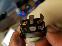
pressure control switches are generally insulated with Teflon tape. This does not make for a good ground. I would like to see a pressure switch which is rated for more than .5 A without a ground terminal. The fusing only helps on both the circuit side and the safety side. You might consider this redundant, some manufacturers do as well (and they skate) under the NEC requirements for bonding. but it doesn't make it right.
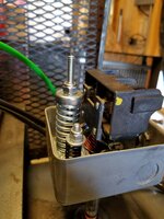
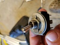
Maybe the OP can show picture of the pressure control valve circuitry for more clarification?
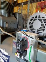
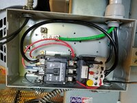
Right but the starter enclosure is grounded(should be). SO why does it matter that the switch isnt bonded via the tank?
What does that have to do with a hot wire shorting to the grounded enclosure?
Why would the presence of a ground terminal effect the current capacity of a pressure switch?
If its not required by NEC, then why do you say its not right?
You really lost me here.


Last edited: