To avoid these ads, REGISTER NOW!

230 Volt Compressor Install / compressor controlled by 115 volt lighting circuit.

nkachur

Well-known member
Joined
Jun 29, 2008
Messages
798
Location
Manitoba Canada
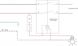
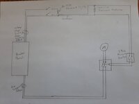
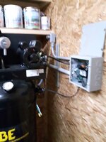
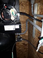
Went out on the weekend and bought a compressor. 60 gallon, 230 volt, 18 cfm, 5 hp and am now planning the install. Before I left I picked up a 230 volt contactor capible of controlling a 5 hp load with a 115 volt Coil so I can auto shut off the compressor using my shop floor ceiling light switch. There has been a ton of discussion on here about doing this but I have yet to see it done. I suspect it is going to take a couple months to get everything set up with life getting in the way but that is OK.

The reason I want to do this is that I am often not in the shop for longer periods of time and feel that:
- leaving the compressor energized will possibly waste electricity.
- I would likely forget to manually shut off the compressor.
- I like learning new things and building a control circuit is definitely something new.

There are likely other reasons but can't think of them right now.

I did talk about this with the electricians at the military base in Winnipeg to ensure this would meet code and was not a completely crazy endeavor after explaining my plan and reasoning they agreed this was reasonable.
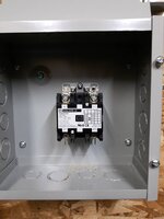
Total additional cost for the contactor and enclosure was about $50 Canadian.
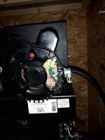
I will get some photo's today and we will start putting things together.

Sent from my SM-G903W using Tapatalk
 
To avoid these ads, REGISTER NOW!

mm08822

Well-known member
Joined
Jan 13, 2012
Messages
5,876
Location
NJ
Yes control circuits can be supplied from different sources – done all of the time in larger control cabinets and PLC based systems.

I would suggest you include an auxiliary contact in a disconnect feeding power to the compressor to cut the control power for safety purposes as this is not the typical residential scenario. If that can’t be easily sourced, then I would suggest putting a toggle switch local to the compressor to kill the control circuit power. Switch would be upstream of all control circuit devices. Both disconnect/switch should be labeled accordingly as you then have 2 sources of power entering the unit.

You also mentioned a contactor. Is this only a contactor or does it have overload protection included? If included, it is a motor starter and the overload contacts need to be separated from the 240 volt circuit if not already done.
If it is not a starter, then your motor will need to have internal OL protection with a manual reset.
 

seanc_mt

Well-known member
Joined
Jul 20, 2015
Messages
285
Please post up a diagram of how you are going to go about this.
 

mytimeyet

Well-known member
Joined
Apr 27, 2010
Messages
128
Location
Micanopy, FL
I did the same thing except I picked off a leg of the 230 to run the contractor and a light
 

Attachments

  • compressor shed.jpg
    compressor shed.jpg
    49.3 KB · Views: 182

klassenl

Well-known member
Joined
Feb 20, 2016
Messages
713
Location
Southern Alberta
My compressor circuit is controlled from my light switch.
If your contactor has a 120 coil you can run a wire from any light to the contactor. When the lights are on the contacts will be pulled in.

In what part of MB do you live. I lived in Winnipeg for 5yrs.
 
OP
N

nkachur

Well-known member
Joined
Jun 29, 2008
Messages
798
Location
Manitoba Canada
Yes control circuits can be supplied from different sources – done all of the time in larger control cabinets and PLC based systems.

I would suggest you include an auxiliary contact in a disconnect feeding power to the compressor to cut the control power for safety purposes as this is not the typical residential scenario. If that can’t be easily sourced, then I would suggest putting a toggle switch local to the compressor to kill the control circuit power. Switch would be upstream of all control circuit devices. Both disconnect/switch should be labeled accordingly as you then have 2 sources of power entering the unit.

You also mentioned a contactor. Is this only a contactor or does it have overload protection included? If included, it is a motor starter and the overload contacts need to be separated from the 240 volt circuit if not already done.
If it is not a starter, then your motor will need to have internal OL protection with a manual reset.
Thanks for the feedback. I am planning on trying to tie the 2 breakers together as the breaker panel is only 10 feet from the compressor location. If that is not possible we will come up with a secondary plan that may involve some labeling and possibly a kill switch. The motor has it's own overload circuit or I likely would have gone with a commercial motor starter unit. Headed out in a few minutes go get the promised pictures. Thanks for the advise and knowledge, always better to go into a situation armed.


Sent from my SM-G903W using Tapatalk
 
OP
N

nkachur

Well-known member
Joined
Jun 29, 2008
Messages
798
Location
Manitoba Canada
My compressor circuit is controlled from my light switch.
If your contactor has a 120 coil you can run a wire from any light to the contactor. When the lights are on the contacts will be pulled in.

In what part of MB do you live. I lived in Winnipeg for 5yrs.
Exactly. Spent quite a while researching this and there was a lot of talk on the boards just never really saw a solution. Now we will document and see how it goes. I live about 1/2 an hour north of the city.

Sent from my SM-G903W using Tapatalk
 
OP
N

nkachur

Well-known member
Joined
Jun 29, 2008
Messages
798
Location
Manitoba Canada
So here a few photo's
The compressor, close up of the motor wiring and pressure switch.
2395cc551333eadc701aa268f29c7852.jpgfe7078315a5019f618f0adb059912478.jpgc2032d4a529dc555f4c6ebf227af20d6.jpg

Sent from my SM-G903W using Tapatalk
 

Attachments

  • c2032d4a529dc555f4c6ebf227af20d6.jpg
    c2032d4a529dc555f4c6ebf227af20d6.jpg
    91.4 KB · Views: 1
  • fe7078315a5019f618f0adb059912478.jpg
    fe7078315a5019f618f0adb059912478.jpg
    85.7 KB · Views: 1
  • 2395cc551333eadc701aa268f29c7852.jpg
    2395cc551333eadc701aa268f29c7852.jpg
    119 KB · Views: 2
OP
N

nkachur

Well-known member
Joined
Jun 29, 2008
Messages
798
Location
Manitoba Canada
And here are the photos of the contactor I chose and enclosure. 0ae43d00bfeeb8ce90cbd82f1fe06042.jpgd8ab8540608d5760434b64e13b9856e4.jpg

Sent from my SM-G903W using Tapatalk
 

Attachments

  • d8ab8540608d5760434b64e13b9856e4.jpg
    d8ab8540608d5760434b64e13b9856e4.jpg
    69.8 KB · Views: 1
  • 0ae43d00bfeeb8ce90cbd82f1fe06042.jpg
    0ae43d00bfeeb8ce90cbd82f1fe06042.jpg
    86.9 KB · Views: 2

wyliesdiesels

Well-known member
Joined
Aug 14, 2012
Messages
19,994
Location
Modesto, CA
I did the same thing except I picked off a leg of the 230 to run the contractor and a light

The diagram isnt quite right.

Why is your contactor coil wired to the T2/load side of the contactor?

It should be connected to the line side- L2.

So here's a few photo's
The compressor, close up of the motor wiring and pressure switch.
2395cc551333eadc701aa268f29c7852.jpgfe7078315a5019f618f0adb059912478.jpgc2032d4a529dc555f4c6ebf227af20d6.jpg

Sent from my SM-G903W using Tapatalk

You dont need a motor starter as the motor has integral overload protection and its switched by the pressure switch.

Make sure the contactor you got is rated for 5 or more HP.
 

Attachments

  • c2032d4a529dc555f4c6ebf227af20d6.jpg
    c2032d4a529dc555f4c6ebf227af20d6.jpg
    89.4 KB · Views: 2
  • fe7078315a5019f618f0adb059912478.jpg
    fe7078315a5019f618f0adb059912478.jpg
    83 KB · Views: 2
  • 2395cc551333eadc701aa268f29c7852.jpg
    2395cc551333eadc701aa268f29c7852.jpg
    115.9 KB · Views: 2
Last edited:
OP
N

nkachur

Well-known member
Joined
Jun 29, 2008
Messages
798
Location
Manitoba Canada
The diagram isnt quite right.

Why is your contactor coil wired to the T2/load side of the contactor?

It should be connected to the line side- L2.


You dont need a motor starter as the motor has integral overload protection and its switched by the pressure switch.

Make sure the contactor you got is rated for 5 or more HP.
I know, that is why I only picked up a contactor for this application. The contactor is a 40 amp contactor rated for 5 hp at 240 volts. For those of you that are interested the contactor is a square d - 8910dpa32v02.
Thanks for the feed back and guidance.

Sent from my SM-G903W using Tapatalk
 
OP
N

nkachur

Well-known member
Joined
Jun 29, 2008
Messages
798
Location
Manitoba Canada
I have gotten a bunch more work done for the compressor install
The conduit and wiring is in place between the panel and contactor. a61d6d4165bf78b75d4dc21c2f6bdef1.jpgda2a3a91a41da2cb806aba37fc87739d.jpg

Sent from my SM-G903W using Tapatalk
 

Attachments

  • da2a3a91a41da2cb806aba37fc87739d.jpg
    da2a3a91a41da2cb806aba37fc87739d.jpg
    147.6 KB · Views: 1
  • a61d6d4165bf78b75d4dc21c2f6bdef1.jpg
    a61d6d4165bf78b75d4dc21c2f6bdef1.jpg
    138.5 KB · Views: 1
OP
N

nkachur

Well-known member
Joined
Jun 29, 2008
Messages
798
Location
Manitoba Canada
I have also ran conduit and 14 Guage rw90 to the florescent lighting on the shop main floor.

Sent from my SM-G903W using Tapatalk
 
OP
N

nkachur

Well-known member
Joined
Jun 29, 2008
Messages
798
Location
Manitoba Canada
Forgot to add pictures on the last post. 2952e02c24fb5d2adcf2d8ef47c41962.jpg8c54873c68dfafb075891fa1b675bafc.jpg8d6884a447bed9da159eb1fa7e5a6692.jpg

Sent from my SM-G903W using Tapatalk
 

Attachments

  • 8d6884a447bed9da159eb1fa7e5a6692.jpg
    8d6884a447bed9da159eb1fa7e5a6692.jpg
    131.6 KB · Views: 1
  • 8c54873c68dfafb075891fa1b675bafc.jpg
    8c54873c68dfafb075891fa1b675bafc.jpg
    66.8 KB · Views: 1
  • 2952e02c24fb5d2adcf2d8ef47c41962.jpg
    2952e02c24fb5d2adcf2d8ef47c41962.jpg
    45.3 KB · Views: 1
OP
N

nkachur

Well-known member
Joined
Jun 29, 2008
Messages
798
Location
Manitoba Canada
And last update for today, I built the studs for mounting the compressor to the platform I am making for it.

Sent from my SM-G903W using Tapatalk
 
OP
N

nkachur

Well-known member
Joined
Jun 29, 2008
Messages
798
Location
Manitoba Canada
These are the studs. 1/8 x 1 1/4 bar with 2 screw holes and a 3" by 1/2" bolt welded ind4db9899154bcfc6c2a1ed85d4db2703.jpgeb6aadb82fab3705604666f7249df169.jpg

Sent from my SM-G903W using Tapatalk
 

Attachments

  • eb6aadb82fab3705604666f7249df169.jpg
    eb6aadb82fab3705604666f7249df169.jpg
    98.8 KB · Views: 1
  • d4db9899154bcfc6c2a1ed85d4db2703.jpg
    d4db9899154bcfc6c2a1ed85d4db2703.jpg
    108.3 KB · Views: 1
OP
N

nkachur

Well-known member
Joined
Jun 29, 2008
Messages
798
Location
Manitoba Canada
Today I got some of the wiring hooked up, the Coil in the contactor really hums.

May have most everything together by the weekend, but time will tell. I had a couple surprises so far, the motor is fed from the pressure switch with 14/2 cable, I was expecting slightly more, like maybe 10 Guage, based on the compressor motor data plate. I am still debating on the size of breaker for the 240 side.
The data plate says 22-22.5 Amps and a service factor of 1. 949865e772455ba342ca9fc3b5194c11.jpg01205acf0a31b5923e0913a0dea2df18.jpg

Sent from my SM-G903W using Tapatalk
 

Attachments

  • 01205acf0a31b5923e0913a0dea2df18.jpg
    01205acf0a31b5923e0913a0dea2df18.jpg
    67.4 KB · Views: 1
  • 949865e772455ba342ca9fc3b5194c11.jpg
    949865e772455ba342ca9fc3b5194c11.jpg
    133.3 KB · Views: 1

mm08822

Well-known member
Joined
Jan 13, 2012
Messages
5,876
Location
NJ
Today I got some of the wiring hooked up, the Coil in the contactor really hums.

May have most everything together by the weekend, but time will tell. I had a couple surprises so far, the motor is fed from the pressure switch with 14/2 cable, I was expecting slightly more, like maybe 10 Guage, based on the compressor motor data plate. I am still debating on the size of breaker for the 240 side.
The data plate says 22-22.5 Amps and a service factor of 1. 949865e772455ba342ca9fc3b5194c11.jpg01205acf0a31b5923e0913a0dea2df18.jpg

Sent from my SM-G903W using Tapatalk

Your schematic in post 7 shows the ps in series with the contactor coil.
Based upon that, I would expect your motor to be wired from the load side of the contactor directly with 10-3 cord. The ps would be wired back to the j-box in series with the lighting power (#14 or #12 depending on lighting ckt cb) and the contactor coil. Wiring it this way will keep the coil off when the lights are on and the comp doesn't call for air.

Temporarily disconnect the contactor from everything and hook the coil up directly to 120vac and see if it still hums loudly. If yes, possibly there is some debris in it.
 

Attachments

  • 949865e772455ba342ca9fc3b5194c11.jpg
    949865e772455ba342ca9fc3b5194c11.jpg
    129.6 KB · Views: 1
  • 01205acf0a31b5923e0913a0dea2df18.jpg
    01205acf0a31b5923e0913a0dea2df18.jpg
    62.8 KB · Views: 1
OP
N

nkachur

Well-known member
Joined
Jun 29, 2008
Messages
798
Location
Manitoba Canada
Your schematic in post 7 shows the ps in series with the contactor coil.
Based upon that, I would expect your motor to be wired from the load side of the contactor directly with 10-3 cord. The ps would be wired back to the j-box in series with the lighting power (#14 or #12 depending on lighting ckt cb) and the contactor coil. Wiring it this way will keep the coil off when the lights are on and the comp doesn't call for air.

Temporarily disconnect the contactor from everything and hook the coil up directly to 120vac and see if it still hums loudly. If yes, possibly there is some debris in it.
You are correct, that is the plan. When I disconnected the pressure switch from the motor I checked the size of the factory interconnect wire and it is only 14 Guage. It seems a little under kill for 22.5 Amps max draw as posted on the motor data plate.

Sent from my SM-G903W using Tapatalk
 
To avoid these ads, REGISTER NOW!

matt_i

Well-known member
Joined
Mar 14, 2008
Messages
10,725
Location
SE Michigan
When you are done I'd place that wiring diagram folded up in the contactor enclosure.

You could also add wire numbers and/or colors to the field wiring and diagram to make it even easier to "re-understand" and troubleshoot. I say this as things that are sharp and fresh in the mind right now may be fuzzy in a couple of years.
 

mm08822

Well-known member
Joined
Jan 13, 2012
Messages
5,876
Location
NJ
You are correct, that is the plan. When I disconnected the pressure switch from the motor I checked the size of the factory interconnect wire and it is only 14 Guage. It seems a little under kill for 22.5 Amps max draw as posted on the motor data plate.

Sent from my SM-G903W using Tapatalk

Ok, good. Wasn't sure if that was just commentary or things went a very different route. Yes 14-3 cord is too small for that motor. I'd go with 10-3.

I would put a 2P40A or 2P50A in for that ckt. Not sure of Ca code, but in US, we can go as high as 250% of motor FLA's for inverse time cb's.
 
OP
N

nkachur

Well-known member
Joined
Jun 29, 2008
Messages
798
Location
Manitoba Canada
I will be getting an engraved plate for the cover of the contactor enclosure. I might even get the wiring diagram on it. I am also going to see about Tieing the 2 breakers together 2 prevent a mishap. The panel is less than 10 feet from the compressor and enclosure in the same utility room.
Once everything is in place I will sort out the permit and will talk to the inspector about the modifications (wire rerouting and likely replacement of the motor leads). I do not expect a problem. The feed wires from the panel to the enclosure are 8 Guage rw90 stranded with crimped lugs in the enclosure. I also ran a 10 Guage stranded rw90 ground with crimped ring terminals at the enclosure.
I am down to the physical installation of the compressor. Breaker selection; I do have a spare 50 amp breaker but do not want to oversize unless it is not any type of safety issue. And some final tidy up of conduit clamping, breaker box labeling and air plumbing. The end is almost here.

Sent from my SM-G903W using Tapatalk
 

mm08822

Well-known member
Joined
Jan 13, 2012
Messages
5,876
Location
NJ
I Breaker selection; I do have a spare 50 amp breaker but do not want to oversize unless it is not any type of safety issue. And some final tidy up of conduit clamping, breaker box labeling and air plumbing. The end is almost here.

Sent from my SM-G903W using Tapatalk

Since you have a 2P50A I would use it - at least try it. By NEC requirements, it is acceptable to use. Maybe you can find someone knowledgeable locally who can verify if 250% of FLA's is ok in Ca.

That cb you have is at least good enough for startup.
 
OP
N

nkachur

Well-known member
Joined
Jun 29, 2008
Messages
798
Location
Manitoba Canada
Since you have a 2P50A I would use it - at least try it. By NEC requirements, it is acceptable to use. Maybe you can find someone knowledgeable locally who can verify if 250% of FLA's is ok in Ca.

That cb you have is at least good enough for startup.
Thanks for the guidance. That is 1 place that things are not clear in the code. Was a little bit of tension on the thread thus morning but it looks like the moderators did some cleanup.

Sent from my SM-G903W using Tapatalk
 
OP
N

nkachur

Well-known member
Joined
Jun 29, 2008
Messages
798
Location
Manitoba Canada
Another step forward and 1/2 a step back. Got the base together for the compressor and put things in place... The studs I made up are too short. But here are things kind of roughed in. Of course it all has to come back apart for new studs, oh well. e17b0ad4e7d4af80f016c54ffd3c586b.jpg2b2bd4cc22e3a38f09d1c0b16fcefad6.jpg543aab2904681b55f253a0432d8a51dc.jpg

Sent from my SM-G903W using Tapatalk
 

Attachments

  • 543aab2904681b55f253a0432d8a51dc.jpg
    543aab2904681b55f253a0432d8a51dc.jpg
    148 KB · Views: 1
  • 2b2bd4cc22e3a38f09d1c0b16fcefad6.jpg
    2b2bd4cc22e3a38f09d1c0b16fcefad6.jpg
    95 KB · Views: 1
  • e17b0ad4e7d4af80f016c54ffd3c586b.jpg
    e17b0ad4e7d4af80f016c54ffd3c586b.jpg
    117.3 KB · Views: 1

Matt Matt

Well-known member
Joined
May 11, 2017
Messages
523
Location
Ontario
Thanks for the guidance. That is 1 place that things are not clear in the code. Was a little bit of tension on the thread thus morning but it looks like the moderators did some cleanup.
Are you getting this installation checked by the ESA? Or no?
 
OP
N

nkachur

Well-known member
Joined
Jun 29, 2008
Messages
798
Location
Manitoba Canada
Got a bunch done tonight. New studs made for the base. Decided on a 40 amp breaker for the panel to not risk overloading the contactor. Breaker installed and panel closed up. Compressor mounted, a few fittings installed and conduit clamps installed as well.

50f512d9bcac7d8f526a17b399f315be.jpge8a72bd81a4814e924f02bba28382580.jpgb18f7226f042b6de419b2ff4fb3b2612.jpgb82c115160d398e340008eace1f8152a.jpg9bb25a5ab95359131dc8ee616cf431fd.jpge49716c78cf760b179b27158a976a0bb.jpg

Sent from my SM-G903W using Tapatalk
 

Attachments

  • b82c115160d398e340008eace1f8152a.jpg
    b82c115160d398e340008eace1f8152a.jpg
    103.2 KB · Views: 1
  • b18f7226f042b6de419b2ff4fb3b2612.jpg
    b18f7226f042b6de419b2ff4fb3b2612.jpg
    116.6 KB · Views: 1
  • e8a72bd81a4814e924f02bba28382580.jpg
    e8a72bd81a4814e924f02bba28382580.jpg
    145.9 KB · Views: 1
  • 50f512d9bcac7d8f526a17b399f315be.jpg
    50f512d9bcac7d8f526a17b399f315be.jpg
    128 KB · Views: 1
  • e49716c78cf760b179b27158a976a0bb.jpg
    e49716c78cf760b179b27158a976a0bb.jpg
    69 KB · Views: 1
  • 9bb25a5ab95359131dc8ee616cf431fd.jpg
    9bb25a5ab95359131dc8ee616cf431fd.jpg
    69.7 KB · Views: 1

larry4406

Well-known member
Joined
Jan 27, 2006
Messages
19,089
Location
Northern Virginia
Do they make shunt trip breakers that drop out (open the circuit) when the coil is deenergized (ie light circuit is turned off)? If so, then wouldn't this be a simple solution?

The shunt trip breakers I am aware of use an energized coil to open the circuit.
 
OP
N

nkachur

Well-known member
Joined
Jun 29, 2008
Messages
798
Location
Manitoba Canada
Do they make shunt trip breakers that drop out (open the circuit) when the coil is deenergized (ie light circuit is turned off)? If so, then wouldn't this be a simple solution?

The shunt trip breakers I am aware of use an energized coil to open the circuit.
They may but do the reclose when the lights are re-energized?
I do know my concept works and the over all cost was only about $50-60 more than just installing the compressor.

I got everything on the electrical side set up today and actually powered up the compressor for the first time. Everything works except I was unable to test the pressure switch and cycling as I have some giant open parts of the air system. Need to go by parts tomorrow.

Made a temporary warning for the control panel. I will get the following typed warning printed on red plastic as the more permanent install. If anyone has any ideas to better the label, let me know.
a6e96e38a6005fd435199873f1b0c34b.jpg6bc6522453e1018ca1197a49042777c8.jpgb5f66a19258ddbc09693df697f7be871.jpg

Sent from my SM-G903W using Tapatalk
 

Attachments

  • b5f66a19258ddbc09693df697f7be871.jpg
    b5f66a19258ddbc09693df697f7be871.jpg
    112 KB · Views: 1
  • 6bc6522453e1018ca1197a49042777c8.jpg
    6bc6522453e1018ca1197a49042777c8.jpg
    102.4 KB · Views: 1
  • a6e96e38a6005fd435199873f1b0c34b.jpg
    a6e96e38a6005fd435199873f1b0c34b.jpg
    129.9 KB · Views: 1
OP
N

nkachur

Well-known member
Joined
Jun 29, 2008
Messages
798
Location
Manitoba Canada
Take 2 on the warning label. 899fda826bf156cdf6fe8aee3a8c16de.jpg

Sent from my SM-G903W using Tapatalk
 

Attachments

  • 899fda826bf156cdf6fe8aee3a8c16de.jpg
    899fda826bf156cdf6fe8aee3a8c16de.jpg
    63.1 KB · Views: 1
OP
N

nkachur

Well-known member
Joined
Jun 29, 2008
Messages
798
Location
Manitoba Canada
You can pin the breakers together too.
I have not been able to find a pin to pin together 2 x 2 Pole square d breakers. Would a machine screw butted on each side of the handles be appropriate?

Sent from my SM-G903W using Tapatalk
 
OP
N

nkachur

Well-known member
Joined
Jun 29, 2008
Messages
798
Location
Manitoba Canada
Got my warning label and new breaker panel labels today from the engraver. 75731ec932a6d8fcfe351198cfebfbe2.jpg5507250a9608814fb0c72e3a5d0f3b7f.jpg422b7f5ad9665125b651bb795ef47c97.jpg

Sent from my SM-G903W using Tapatalk
 

Attachments

  • 422b7f5ad9665125b651bb795ef47c97.jpg
    422b7f5ad9665125b651bb795ef47c97.jpg
    128.8 KB · Views: 1
  • 5507250a9608814fb0c72e3a5d0f3b7f.jpg
    5507250a9608814fb0c72e3a5d0f3b7f.jpg
    81.1 KB · Views: 1
  • 75731ec932a6d8fcfe351198cfebfbe2.jpg
    75731ec932a6d8fcfe351198cfebfbe2.jpg
    118 KB · Views: 1

Lsversaw

Member
Joined
May 31, 2017
Messages
11
Looks great. Those labels are an example of how a competent owner can do a higher-quality job than you can feasibly get from a contractor. I've seen a contractor throw a tantrum when I asked for something better than "good enough".

Well done!
 
OP
N

nkachur

Well-known member
Joined
Jun 29, 2008
Messages
798
Location
Manitoba Canada
Looks great. Those labels are an example of how a competent owner can do a higher-quality job than you can feasibly get from a contractor. I've seen a contractor throw a tantrum when I asked for something better than "good enough".

Well done!
Thanks. It is amazing what a motivated person can do, if you are not afraid to try and not afraid to research or ask.

Sent from my SM-G903W using Tapatalk
 
OP
N

nkachur

Well-known member
Joined
Jun 29, 2008
Messages
798
Location
Manitoba Canada
Added a 120v switch to cut power to the contactor when I don't what the compressor cutting in and I want both banks of shop floor lights on. c345b3107d58dbe48150b5ea9f1c8092.jpg

Sent from my SM-G903W using Tapatalk
 

Attachments

  • c345b3107d58dbe48150b5ea9f1c8092.jpg
    c345b3107d58dbe48150b5ea9f1c8092.jpg
    98.5 KB · Views: 1

Milton Shaw

Well-known member
Joined
Feb 11, 2011
Messages
4,835
You might also consider adding an electric solenoid valve to the air outlet from the tank. That way you would have a full tank whenever you turned on the lights. Now with the power off it could take 10 to 15 minutes before you have air to work once you turn the lights on. Also a lot of unneeded noise every time you turn the lights on. Just wire it in parallel with the contractor coil.
 
To avoid these ads, REGISTER NOW!
Top Bottom