To avoid these ads, REGISTER NOW!

3 - Point Fork Attachment

airrj

Well-known member
Joined
Apr 4, 2008
Messages
137
Location
Wide Wonderful Wyoming
I have a new project for a friend that I am starting to design.

He has a 60 hp Kubota tractor with a Cat. II 3-point hitch that is rated for 3000#. He also has a 200 gallon skid mount sprayer that he has used for several years. The skid has been mounted on an old re-welded time and time again 3-point Carry-All.

Two things recently happened. First, the Carry-All snapped in half again at the point of one of the old welded on patches. Second, he was given a pair of 3500# forklift forks. A major score.

So, my task is to build a lifting 3-point attachment to carry the sprayer with the forks.

This is a similar style of sprayer:

Sprayer.jpg


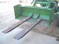
This is the style of forks that he has:

Bucket%252520Forks.jpg


Here are my first thoughts on a design for the frame.

Chuck%252520Forks%252520Rear.jpg


Chuck%252520Forks%252520Side.jpg


The plan is a 2" solid bar across the top for the forks to hang from. The bar will go through each of the four vertical plates rather than just a **** weld. The verticals are 1/2" x 6" HRS. The two horizontal members will be 8" x 13.75# C-Channel. This C-Channel is 2-3/8" deep and the web is .3" thick.

The 3 - point hitch is 32" wide and 24" tall. The mounting points are shown by the little orange marks on the drawings.

Any thoughts? Too overbuilt for the application? Too light weight? All of the sizing has been by seat of the pants engineering. But if you saw the piece that was carrying this sprayer before, you would be amazed that it worked for 2 years. I have a large steel order going in this month, so I have to order steel soon, however the project won't likely be built until fall.

Thanks for your help.
 
To avoid these ads, REGISTER NOW!

EdT

Well-known member
Joined
Sep 21, 2010
Messages
1,104
Location
North Georgia
Well, "seat of the pants" wise, it certainly looks strong enough. I assume that the forks will pass through the rectangular fork openings in the frame of the sprayer. If the forks are not long enough to go all the way through, it will be important that the tank is located near the tractor or the next failure point will be the bottoms of the square cut outs on the sprayer. Also, can the ends of the forks actually get down low enough to get under the sprayer frame and/or into the fork slots. The whole rig full of water will weigh close to a ton so you don't want to be trying to lift it onto the forks if they won't go low enough. I suspect that can be accommodated by adjusting the top link on the three point, but it's worth thinking about before you make it .
 

BD1

Well-known member
Joined
Mar 18, 2007
Messages
4,602
Location
north side
Here are some post from the WELDINGWEB site.
http://weldingweb.com/forum.php

http://weldingweb.com/showthread.php?306971-stuff-for-my-tractor&highlight=forks

http://weldingweb.com/showthread.php?285921-Tractor-forks&highlight=forks

This one is a 3 point , other pics were for ideas.
http://weldingweb.com/showthread.php?20534-3-Pnt-Fork-lift&highlight=forks

If pics don't show, you may have to join.

For your design it will be overkill but I build the same way. Check the manufacture pics on this goggle search. Some are so light duty but still rated high .
https://www.google.com/search?q=3+p...v&sa=X&ei=ZNObVfLmEYbBggT29Za4Bg&ved=0CCUQsAQ

Look at this one , http://www.ruralking.com/king-kutte...m_medium=cpc&gclid=CPXGlLeQycYCFQyoaQodI4gKVg
 

Attachments

  • 060631448_1.jpg
    060631448_1.jpg
    18.2 KB · Views: 23

sberry

Banned
Joined
Jun 18, 2005
Messages
35,747
Location
Brethren, Michigan
I have seen the same cheaper somewhere but the steel alone will be near that, its one thing to cobble it all for free but I will buy it painted and ready to go for that. Can use it today vs sitting on a bunch of steel waiting to spend days to fab.
 
Last edited:

larry_g

Well-known member
Joined
Apr 28, 2007
Messages
16,885
Location
oregon
I have one similarly built. One failure point is at the top link. With the pin holes above the cross brace it imparts a twisting moment to the brace and will literately twist that C channel. That was our failure. Also keep in mind that the distance vertically between the lower and upper attachment points will determine if the forks stay level when lifting or if they come up at a changing angle. Usually this can be dealt with on the tractor end of the upper link, but the equipment end has to be right also. Make sure it does what you want.

lg
no neat sig line
 

BD1

Well-known member
Joined
Mar 18, 2007
Messages
4,602
Location
north side
I have one similarly built. One failure point is at the top link. With the pin holes above the cross brace it imparts a twisting moment to the brace and will literately twist that C channel. That was our failure. Also keep in mind that the distance vertically between the lower and upper attachment points will determine if the forks stay level when lifting or if they come up at a changing angle. Usually this can be dealt with on the tractor end of the upper link, but the equipment end has to be right also. Make sure it does what you want.

lg
no neat sig line

IF you have rear remote hydraulics, a hydraulic cylinder can be used for the center link. That would be way too easy. Hard art is the hydraulics.
 

stihlntime

Well-known member
Joined
Jun 2, 2015
Messages
603
Location
SW Missouri Ozarks
I have a round bale mover built like the rural king picture. I have lifted in excess of 4000 lbs without an issue. If he needs the leveling feature just use a cylinder for the 3rd link.
 
OP
A

airrj

Well-known member
Joined
Apr 4, 2008
Messages
137
Location
Wide Wonderful Wyoming
Thanks for the input. The point of the project is to build something, not buy it. So thanks for the suggestions, but I am looking more at the design of this unit.

EdT, Yes the tank of the unit sits forward and is closest to the tractor. And the frame will fit the forks fortunately.

larryg, The only time that I am concerned with the angle is while loading the sprayer. The unit doesn't need to sit level while in operation, so my plan is to mock it up on the flat floor that the sprayer is stored on and go from there.

The upper point I figured would see significant load. My drawings don't show it well, but my plan is to have the top link mount sandwiched between the middle two 1/2" plates. I was hoping that the torsional twist would be held in check with this.

Here is a quick sketch of what I am planning for the two mid plates:

Middle%252520plate.jpg


The two plates would be spaced appropriately for the top link. They would be welded around the two C-Channels and the round.
 

larry_g

Well-known member
Joined
Apr 28, 2007
Messages
16,885
Location
oregon
Here is a quick sketch of what I am planning for the two mid plates:

Middle%252520plate.jpg


The two plates would be spaced appropriately for the top link. They would be welded around the two C-Channels and the round.

The sketch looks like a good design. I would think twice about welding in the upper bar. What if you have to remove to fix or change a fork? Slide in with a couple of pins to retain it should be fine.

lg
no neat sig line
 

sberry

Banned
Joined
Jun 18, 2005
Messages
35,747
Location
Brethren, Michigan
The design is fundamentally fine, the reason I suggested laying this off was simply cost and partially due to the fact that this is heavy, way overbuilt, adds substantial load to the tractor before it gets off the ground.
I remember the first rel trailer I built, never did use it, was probably a lesson in ******* away a fistful on new steel and I havnt made the total mistake since. A good reason to do diy is economy, maybe its not an issue here and irrelevant to carry the weight mostly to use some free forks.
there could be economy of weight here, pipe instead of solid, 4 inch channel, all 4 inch plate, wouldn't need notches. Normal skids are 42 wide and forks go to 38 or so. If a guy is doing much rigging there could be some benefit of some extra width and moveable forks.
 
Last edited:
To avoid these ads, REGISTER NOW!

sberry

Banned
Joined
Jun 18, 2005
Messages
35,747
Location
Brethren, Michigan
If its main purpose was the sprayer may be inclined to take a look at adding to the existing skid? We fix stuff like that up all the time that doesn't work right, its neat when you can do it on the easy and cheap.
 

SVS

Member
Joined
Nov 9, 2012
Messages
9
Location
Nebraska
Long time lurker, have to jump in....

I'd suggest 4"x4" by 1/4" wall square tube. You need the torsional stiffness that closed shapes provide.

No pictures at hand, but years ago built a front end loader attachment for a 4020 JD for same style forks, and the 4x4 tube has been flawless.
 

sberry

Banned
Joined
Jun 18, 2005
Messages
35,747
Location
Brethren, Michigan
I am sure it has worked due to the fact its extra heavy but look at the amount of steel and where its at in the pic above. The forks from the OP are hanging but the principle is the same, there is really only one strong part required and that is the top beam for the 3 pt, the drag arms are connected behind the fork, essentially a chain would suffice here.
There is a lot of misconception about some of this in the respect that it doesn't have to be as strong as it can be.
 

sberry

Banned
Joined
Jun 18, 2005
Messages
35,747
Location
Brethren, Michigan
I have wasted a lot of time and effort fabricating, designs when I should have been copying others. I use copy loosely due to the fact that it doesn't mean copy any others but today I stick near penciled out designs ad go from there while not straying too far from the principle. On some machines adding a few hundred # or some slight geometry flaws wouldn't mean much but relatively small tractors are another matter.
As I said, reason I mention this is that I am not immune and still continue to do battle where its difficult. I have a fab shop, its super tempting to w2ant to save or build. I fixed a part a while back was foolish to do and can only hope I can remind myself of this when the math is bigger and use it as a lesson.
Pic in a minute.
 

sberry

Banned
Joined
Jun 18, 2005
Messages
35,747
Location
Brethren, Michigan
OK, had to take a gearbox apart and back for weather check and coffee.
While these are not adjustable they were built by the real engineer at the fork store.
They are for that class of tractor and I forget a bit about the math but you can see we goobered on apps for minor changes and we can use a hydro top link but I would rather not. You can find out why if you feel like various designs,, ha but I got tractors with tires too big, too tall, things that seem small can present bigger issues.
 

Attachments

  • fork box.jpg
    fork box.jpg
    148 KB · Views: 24

sberry

Banned
Joined
Jun 18, 2005
Messages
35,747
Location
Brethren, Michigan
As I look at it again the original design from the OP doesn't look all that bad, just heavier than it needs. I might be tempted to copy the Rural King but let the tube run out both ends and add a set of hangers and rod for the forks. If I copy and make changes I usually use a tube a gage thicker than the mfg version on something like this.
The engineer used the minimum and economical to hit a price target, going up a thickness doesn't add a lot of cost or weight.
Some consideration would be given to scrap or free.
 

MagnumForce

Well-known member
Joined
Jun 3, 2014
Messages
1,392
Location
Ohio
Some serious over engineering going on here and insistence on using those forks just because.
 

why worry

Well-known member
Joined
Oct 3, 2014
Messages
301
A lot of good comments here. A lot of forks will have a 2" eye so you will want 1 15/16" bar stock. I would also get shaft collars and weld them to the side plates. This will allow you to remove the forks if needed or replace the shafts when they get bent. I have bent one myself with my 245 loader on a JD 2555. Your design is similar to my loaders fork attachment. Looks like a fun project that could be adapted to a front loader quick release in the future.
 
To avoid these ads, REGISTER NOW!
Top Bottom