To avoid these ads, REGISTER NOW!

5 hp air compressor magnetic starter wiring

Marinegrunt

Well-known member
Joined
Jan 7, 2017
Messages
47
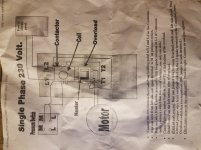
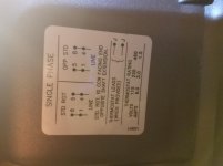
Can someone help me figure out the wiring for the magnetic starter please. They sent a diagram with the starter but it's a little different than the starter. The jumpers were already installed but they don't correspond to the diagram. I'll post some photos below.

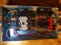
Top black and white/black wires are power coming from 30 amp fusible switch. Bottom black and white/black are wires going to motor. Red wires are the jumpers. Green/orange is the line from the pressure switch. Green/blue is the motor from the pressure switch.

I thought I had it correct with how it's hooked up in the pictures below but it blew one of the fuses.

Thanks
 

Attachments

  • 20170131_183304.jpg
    20170131_183304.jpg
    142.5 KB · Views: 133
  • 20170131_183330.jpg
    20170131_183330.jpg
    134.1 KB · Views: 103
  • 20170131_183348.jpg
    20170131_183348.jpg
    144.3 KB · Views: 107
To avoid these ads, REGISTER NOW!

wyliesdiesels

Well-known member
Joined
Aug 14, 2012
Messages
20,031
Location
Modesto, CA
A few things.

First, the orange 10/2 nm-b is too small by code since u need 35a wire for a 5HP motor. Shouldve used #8/2 nm-b or #10 THHN.

Second, green should not be used for anything but grounding.

Third, its a little hard to tell how u have it wired because of all the extra slack in the wire.

But if the green wire goes from L1 to the pressure switch then to one side of coil and the red jumper goes from L2 to the overload relay then to the other side of the coil it is wired correctly.

If u can remove the slack in the wire it would be a little easier to see.

Im not sure what u meant about motor from pressure switch.
 

Trey T

Well-known member
Joined
Aug 3, 2011
Messages
3,749
Location
Houston, TX
Based on the given info, the relay coil wiring is wired proper enough to provide power out of the T1 and T2 (to the motor). Side note - that coil needs to be rewired to have protection (fuse/overload protection) but that's not important at the moment.

To move forward, I suggest you remove the wires from T1 T2 (the motor) and with a meter to see if you get power from T1 T2. If you do get 240V, then there's a wiring problem to the motor - SIMPLE AS THAT.
 

mm08822

Well-known member
Joined
Jan 13, 2012
Messages
5,988
Location
NJ
Based on the given info, the relay coil wiring is wired proper enough to provide power out of the T1 and T2 (to the motor). Side note - that coil needs to be rewired to have protection (fuse/overload protection) but that's not important at the moment.

To move forward, I suggest you remove the wires from T1 T2 (the motor) and with a meter to see if you get power from T1 T2. If you do get 240V, then there's a wiring problem to the motor - SIMPLE AS THAT.

Since you didn't specify when the fuse blew, I would suggest the additional checks to the above troubleshooting tip.

1) Power down and remove wires from L1/L2. Power back up and confirm 240 vac between them, 120vac to ground on each and no blown fuses.
2) Power down and reconnect L1/L2.
3) Disconnect Control circuit (Pressure switch & O/L) wiring and motor T1/T2 leads.
4) Power up and confirm no blown fuses - 240vac present at L1/L2.
5) Power down and reconnect control circuit. If pressure switch has on/off lever turn it off.
6) Power up and confirm no fuse blown. - 240vac present at L1/L2.
7) Turn on pressure switch lever. Coil should pull in. - 240vac present at L1/L2 and now T1/T2. (If no lever on p.s. then it probably will turn right on unless some other switch present.
8) If all good so far, measure the resistance to ground on each motor lead T1/T2 and across T1/T2. T1- grd = open, T2 - grd = open, T1-T2 = tenths of ohms to a couple of ohms.

Also what fuses are you using? Need full fuse data as there are different time curves for the same amperage fuse. Send pic of motor nameplate too.
 
OP
M

Marinegrunt

Well-known member
Joined
Jan 7, 2017
Messages
47
Thanks for some great replies and help.

I did not realize the 10 gauge wire could be used only if stranded. I will definitely change that out. My green wires with tape are temporary. It's only a 3 foot run and was all I had on hand. That will be changed.

I didn't even think about unhooking t1 and t2 and checking for power. I actually wired it different than I did have it in the picture above. I now have a jumper from L1 to left coil. Overload to L2. Pressure switch to right coil. Other wire from pressure switch to overload.

I didn't mean to change things on you but found some info last night. Still had the same issue tho. I just ran through all of the checks you guys gave me and everything tested good. I unhooked motor from t1 and t2. Powered breaker and coil sucked it and got 240. It's a brand new Baldor L1430T motor. I did just ohm it and from t1 to ground I got 1. T2 to ground 1. T1 to t2 I got .8. It's a cheap hf meter so probably not super accurate.

I wonder if it's something stupid like the belt being too tight. I can easily turn it by hand tho. I went by the manual for adjusting. It probably is a touch on the tight side but figured new belts would stretch a bit.

You can hear what sounds like the motor humming right when I flip the breaker. (I bypassed the fusible switch for the time being) I instantly flipped it off. I heard the same thing when the fuses in switch blew. At the time I didn't know if the magnetic starter made some noise so wasn't sure it was the motor. Now that I know the coil is working right it had to be the motor.

I'm going to unhook the belts just to rule it out. I'm going feel like an idiot if that's it but I don't think it is. If the motor ohmed good, and the starter is working right, could it be anything else?

Thank you for all of the help.

One last thing. The motor has the blue and yellow 10 gauge wire for power but it also has like #12 red and a black. I just capped them off. They aren't used for anything are they?
 
Last edited:

md21722

Well-known member
Joined
Nov 30, 2015
Messages
1,840
Location
Mt Juliet, TN
If you look motor T1 and T2 and connected them straight to the circuit breaker hots, and it doesn't spin, the motor is either wired incorrectly or DOA.

Have you verified the wiring inside the motor? I would start there.
 

wyliesdiesels

Well-known member
Joined
Aug 14, 2012
Messages
20,031
Location
Modesto, CA
Thanks for some great replies and help.

I did not realize the 10 gauge wire could be used only if stranded. I will definitely change that out. My green wires with tape are temporary. It's only a 3 foot run and was all I had on hand. That will be changed.

I didn't even think about unhooking t1 and t2 and checking for power. I actually wired it different than I did have it in the picture above. I now have a jumper from L1 to left coil. Overload to L2. Pressure switch to right coil. Other wire from pressure switch to overload.

I didn't mean to change things on you but found some info last night. Still had the same issue tho. I just ran through all of the checks you guys gave me and everything tested good. I unhooked motor from t1 and t2. Powered breaker and coil sucked it and got 240. It's a brand new Baldor L1430T motor. I did just ohm it and from t1 to ground I got 1. T2 to ground 1. T1 to t2 I got .8. It's a cheap hf meter so probably not super accurate.

I wonder if it's something stupid like the belt being too tight. I can easily turn it by hand tho. I went by the manual for adjusting. It probably is a touch on the tight side but figured new belts would stretch a bit.

You can hear what sounds like the motor humming right when I flip the breaker. (I bypassed the fusible switch for the time being) I instantly flipped it off. I heard the same thing when the fuses in switch blew. At the time I didn't know if the magnetic starter made some noise so wasn't sure it was the motor. Now that I know the coil is working right it had to be the motor.

I'm going to unhook the belts just to rule it out. I'm going feel like an idiot if that's it but I don't think it is. If the motor ohmed good, and the starter is working right, could it be anything else?

Thank you for all of the help.

One last thing. The motor has the blue and yellow 10 gauge wire for power but it also has like #12 red and a black. I just capped them off. They aren't used for anything are they?

The issue isnt that u should use stranded wire. I never said anything about that. THHN comes in solid and stranded. Its the ampacity of the NM wire thats the issue. #10 nm-b and #10 THHN has 2 different ampacities.

However that being said, its best to use stranded for a compressor.

The control wiring will work as u have it.

the values u got when u ohmed the motor shows a possible issue. The hot legs should have NO resistance to ground. Thats why mm08822 said testing from T1 and T2 to ground should how as open. Is the meter digital or analog? maybe the meter shows 1 instead of OL when the circuit is open.

If it was due to too tight of a belt then the overload would trip.

And the last thing is you have the motor hooked up wrong.

According to the diagram on their site, leads 1- blue and 8- red are suppose to be connected to T1 and 4- yellow and 5-black connect to T2.

http://www.baldor.com/catalog/L1430T#tab=%22drawings%22

If you look at the nameplate it should have this info.

Post a pic here for everyone to see.
 
OP
M

Marinegrunt

Well-known member
Joined
Jan 7, 2017
Messages
47
I wired it directly and also took the belts off but it's still humming. Is there anything worth checking inside or should I contact the place I bought it from? I got it online so would be nice if it's something simple. It might end up being a pain trying to return it.
 

wyliesdiesels

Well-known member
Joined
Aug 14, 2012
Messages
20,031
Location
Modesto, CA
I wired it directly and also took the belts off but it's still humming. Is there anything worth checking inside or should I contact the place I bought it from? I got it online so would be nice if it's something simple. It might end up being a pain trying to return it.

did u read what i said above about the leads in the motor? :dunno:
 

mm08822

Well-known member
Joined
Jan 13, 2012
Messages
5,988
Location
NJ
Hooking up the blue and yellow only is for the motor run winding.
The black and red leads are for the start winding. If you don't also hook up the start winding, the motor will not be able to move, and give you the results you are getting - lots of current flow due to no counter emf being generated and fuses blow/cb tripping.

Connect as Wylie stated above. Confirm running in proper direction. If not changes leads as indicated on nameplate for opposite direction.

Also confirm your ohmmeter display - "1" = open??? What does it display when meter leads connected together? and when separated? Not "OL"?
 
OP
M

Marinegrunt

Well-known member
Joined
Jan 7, 2017
Messages
47
We must've posted the same time. Thanks for explaining the thhnext and amperage.

I should've just hired an electrician for this. I know house wiring but haven't messed with a starter or motor this big. The Internet can get you in trouble sometimes.

I'll hook it up the correct way and report back. Thanks!
 

mm08822

Well-known member
Joined
Jan 13, 2012
Messages
5,988
Location
NJ
We must've posted the same time. Thanks for explaining the thhnext and amperage.

I should've just hired an electrician for this. I know house wiring but haven't messed with a starter or motor this big. The Internet can get you in trouble sometimes.

I'll hook it up the correct way and report back. Thanks!

It's not a big deal (this time) as long as you didn't let the smoke out.
But two things as pointed out - up the 10's to 8's and rip that green wiring out that you are using as current carrying conductors and replace with black or red or anything other than white.
 
OP
M

Marinegrunt

Well-known member
Joined
Jan 7, 2017
Messages
47
I haven't swapped them yet but feeling better because I'm sure that's it. I'm not sure which way the compressor pump is suppose to turn. I haven't seen this one run. It's an older Curtis E-50. Maybe by looking at the flywheel someone will know?
 

Attachments

  • 20170201_211333.jpg
    20170201_211333.jpg
    138.7 KB · Views: 39

mm08822

Well-known member
Joined
Jan 13, 2012
Messages
5,988
Location
NJ
I haven't swapped them yet but feeling better because I'm sure that's it. I'm not sure which way the compressor pump is suppose to turn. I haven't seen this one run. It's an older Curtis E-50. Maybe by looking at the flywheel someone will know?

Look for an arrow on the flywheel side.

If the belt is disconnected now, get the motor running first before worrying about rotation.
 

mm08822

Well-known member
Joined
Jan 13, 2012
Messages
5,988
Location
NJ
I found a FS-Curtis manual on aircompressordirect and the manual stated:
"4. Check cooling fan rotation. Fan blades of the compressor flywheel force ambient air across fins of the intercooler and cylinder heads."

You may want to go there and see if your unit is there or if that instruction is consistent with many curtis units.

I would say then rotation is CCW as you look at the shaft end of the motor/compressor.
 
Last edited:
OP
M

Marinegrunt

Well-known member
Joined
Jan 7, 2017
Messages
47
I have my wire list ready and getting it tomorrow. We don't have code enforcement here but I try and do things rigHT.

I hooked it up and it's running. I did find an arrow on the flywheel and do have to switch directions. Do I just swap the red and black?
 

Attachments

  • 1486006541712613549614.jpg
    1486006541712613549614.jpg
    132.6 KB · Views: 37
OP
M

Marinegrunt

Well-known member
Joined
Jan 7, 2017
Messages
47
Thank you very much for all of the help. I have an okay understanding of wiring so as long as I have some help in certain areas I can usually get it. That being said I messed up not coming here first. I thought I had it all figured out by the reading I did. I sure was wrong. I feel fortunate I didn't mess my new motor up.

To answer a previrus queston I believe my meter does say 1 when open. I'll have to check when I get home. It did for every test except the one that was .8.

I'm on my way to get the wire that Wyliesdiesels helped explain, along with others, to get me on the right track. Can I get by with #10 thhn since it's rated at 35 amps? Seems like a lot use that. I have 1/2" flexible conduit on hand already. I think #8 would require 3/4 tho. I do want it to be right.

Thanks again for getting my compressor going.
 
To avoid these ads, REGISTER NOW!

Trey T

Well-known member
Joined
Aug 3, 2011
Messages
3,749
Location
Houston, TX
Based your case, the wiring from the breaker box is important but not as important as the overload protection w/ your starter. From what I understand, that overload protection of your starter supposed to trip instead of your "30 amp fusible switch". That tells me that your overload protection (heater strip located on left) is sized too large, likely for 40amp for 7.5hp motor (stated on name plate) - it's a critical component to protect your motor.
 

md21722

Well-known member
Joined
Nov 30, 2015
Messages
1,840
Location
Mt Juliet, TN
You need only #10 THHN - go with stranded rather than solid THHN - its only going a few feet. Upsizing due to voltage drop of distance is not needed. Over 50 feet you would need look at upsizing.

The magnetic starter has a thermal O/L - a heater element - in this case the fuses/breakers popped first.
 

Trey T

Well-known member
Joined
Aug 3, 2011
Messages
3,749
Location
Houston, TX
so i'm trying to understand the function of the heater strip better ... the heater strip only pop if it's overloaded for a longer period of time?
 
OP
M

Marinegrunt

Well-known member
Joined
Jan 7, 2017
Messages
47
Thanks for the link Matt. I think I had it wired correctly from the start except for the motor itself. I read somewhere that the red and black off the motor was for thermostat or something. That sure was wrong.

Picked up all my thhn stranded today. Will probably pull it this weekend. I also ordered a new pressure switch. I can't seem to keep the compression fitting from leaking. It's original so I think around 1981. This thing sure puts out the air. Much better than my old 2 hp 33 gallon Craftsman.

Am I good to go on my heater? I believe listing said it was sized for a 5 hp motor. It was included with the starter but had to look at a chart to choose the size I needed. It was an eBay purchase but from a business.
 

mm08822

Well-known member
Joined
Jan 13, 2012
Messages
5,988
Location
NJ
First picture shows B40 heater. That's in the 20A range...

The B40 heater is way oversized for that n/p FLA value. In a SQD nema 1 enclosure with a single phase class 8911 starter, OP should be using a B28 heater (20.0 - 20.8a). The B40 is 3 sizes too big - minimal motor protection at best.

Go to grainger catalog page 170 and you can find this info yourself. Print the page, its easier to follow.

https://www.grainger.com/content/general-catalog?pagelabel=170&search=1H627

http://www.baldor.com/catalog/L1430T#tab="nameplate"
 
Last edited:

mm08822

Well-known member
Joined
Jan 13, 2012
Messages
5,988
Location
NJ
Thanks for the link Matt. I think I had it wired correctly from the start except for the motor itself. I read somewhere that the red and black off the motor was for thermostat or something. That sure was wrong.

Picked up all my thhn stranded today. Will probably pull it this weekend. I also ordered a new pressure switch. I can't seem to keep the compression fitting from leaking. It's original so I think around 1981. This thing sure puts out the air. Much better than my old 2 hp 33 gallon Craftsman.

Am I good to go on my heater? I believe listing said it was sized for a 5 hp motor. It was included with the starter but had to look at a chart to choose the size I needed. It was an eBay purchase but from a business.

If it had a tstat in it, the leads would be brown. Tstat shows as optional on cut sheet. Refer to the Baldor motor link in my last post. You should download that cut sheet for future reference.
 

mm08822

Well-known member
Joined
Jan 13, 2012
Messages
5,988
Location
NJ
so i'm trying to understand the function of the heater strip better ... the heater strip only pop if it's overloaded for a longer period of time?

Overload heaters do exactly what their named to do, they heat up. They heat up a solder pot that has a spring loaded ratchet frozen by the cold solder. When the solder gets hot and fluid it allows the spring loaded ratchet to rotate and open the internal overload contacts. (Like a cocked trigger on a pistol.) Not until the solder freezes again, can you reset the overload. This drops out the coil to the starter (unless it's jammed).

The heaters elements are made up of different ratios of metals to provide the correct amount of heat to melt the solder at a particular amperage running through them. Analogous to a fuse except o/l heaters are not self destructing like a fuse element. There are different classes of overload relays that basically give you relatively more time from 10 secs to 30 secs before tripping - class 10, 20, and 30.
 
Last edited:
OP
M

Marinegrunt

Well-known member
Joined
Jan 7, 2017
Messages
47
Great info MM. Thanks for that. I just wonder how many others have the wrong heater being that it's sold as a package. I have a grainger about 30 minutes away so will probably head over and get the correct one today. Menards is 20 minutes but not sure if they would sell heaters or not.

Thanks again.
 

mm08822

Well-known member
Joined
Jan 13, 2012
Messages
5,988
Location
NJ
My 5HP starters came w B36 heaters. My motors have thermal protection. I am not a whiz on heaters.

Your 5 hp might not have the same FLA's as OP. B36 is only 1 size below B40. Next size below B36 is B32, then B28.

Great info MM. Thanks for that. I just wonder how many others have the wrong heater being that it's sold as a package. I have a grainger about 30 minutes away so will probably head over and get the correct one today. Menards is 20 minutes but not sure if they would sell heaters or not.

Thanks again.

Forget Menards or any box store - they won't be carrying o/l heaters. Go to elect supply house selling SQD or grainger, etc.

Do NOTE: If your enclosure has a heater table pasted inside of it, use that table to determine heater size. Key details can be missed in any thread with all of this internet fact-finding and easter egg hunting that goes on. The longer a thread gets, the scarier it gets!:scared:
 
OP
M

Marinegrunt

Well-known member
Joined
Jan 7, 2017
Messages
47
I will definitely take a look at the heater table.

One more question for the pro's. I have my compressor in a room behind the garage. There's a door in the corner of the garage, about 5 stair treads, and that leads to aboit a 10'x30' room. Our yard is graded for a walkout so i assume that's why it drops a half a level. At the other end of the narrow room a door leads to the back patio so there has to be somewhat of a walkway through there. I am going to eventually move the garage door by the stairs to the other end. Anyways, the compressor is closer to the wall than it probably should be since I have storage cabinets on the other side. I'd like to have a fan running over the pump for added insurance until I move the door and can then move the compressor further away from the wall. I'd like for the fan to kick on and off with the compressor. Can I do this my taking a 110v fan or blower, hooking the hot to one of the 240v legs on the starter (t1 or t2) and running the neutral back to the main panel? I have a small fan off of an old humidifier that would work good or even a floor fan.

What do you think?
 
Last edited:
OP
M

Marinegrunt

Well-known member
Joined
Jan 7, 2017
Messages
47
That makes sense. I guess the wiring would be a little more involved or atleast over my head. I'm guessing it would involve splicing into the pressure switch into overcurrent protection for the fan. What I'm pretty much saying is I think I'll just turn the fan on by hand.
 

wyliesdiesels

Well-known member
Joined
Aug 14, 2012
Messages
20,031
Location
Modesto, CA
That makes sense. I guess the wiring would be a little more involved or at least over my head. I'm guessing it would involve splicing into the pressure switch into overcurrent protection for the fan. What I'm pretty much saying is I think I'll just turn the fan on by hand.

No the pressure switch and control circuit wont provide different overcurrent protection than the breaker provides.

By different what i meant was inline fuse. Wouldnt be hard to do. But you will need to pull a neutral wire from panel to compressor.

May be easier to just plug a fan into a switched outlet controlled by switch near man door. Or even better. Get a temperature controller for the fan.
 

matt_i

Well-known member
Joined
Mar 14, 2008
Messages
10,730
Location
SE Michigan
There's a couple of options. Easiest would be an auxiliary Normally Open contact that you install onto the main motor starter. Use that contact to start up a relay that switches on your 120vac circuit. Use standard Buss-type fuses rated for voltage and amp for the fan.

You could also install another 240vac-coil relay that's wired in parallel with the motor, and then use the NO-contact on that same relay to switch 120vac to the fan.

Its possible the pressure switch could be used if it has a separate set of contacts AND the contacts act in the same manner, iow, you can't have a normally closed/normally open setup on the pressure switch. Have to have a NC-NC setup...
 
OP
M

Marinegrunt

Well-known member
Joined
Jan 7, 2017
Messages
47
Thanks Matt. All of that is over my head. The only time I would worry about an auxillary fan would be when using the blast cabinet due to the compressor running more. The pressure switch does have 2 sets of contacts.

Wylie....I understand the separate overcurrent. I just figured since it would need separate overcurrent I couldn't wire off of the starter. Could I just run off of t1, install inline fuse, and run neutral from panel? I'd have to look at the amps on the fan but I wouldn't think it would pull many so wouldn't need a big fuse. I do like the idea of a switch near the door or I could even put it by the blast cabinet. I think that would be the easiest solution for me. I could even tie the fan into the blast cabinet light switch so they both come on at the same time. I might need a beefier switch tho.
 
To avoid these ads, REGISTER NOW!
Top Bottom